 wombatics
-
1Picking a RC Car
![]()
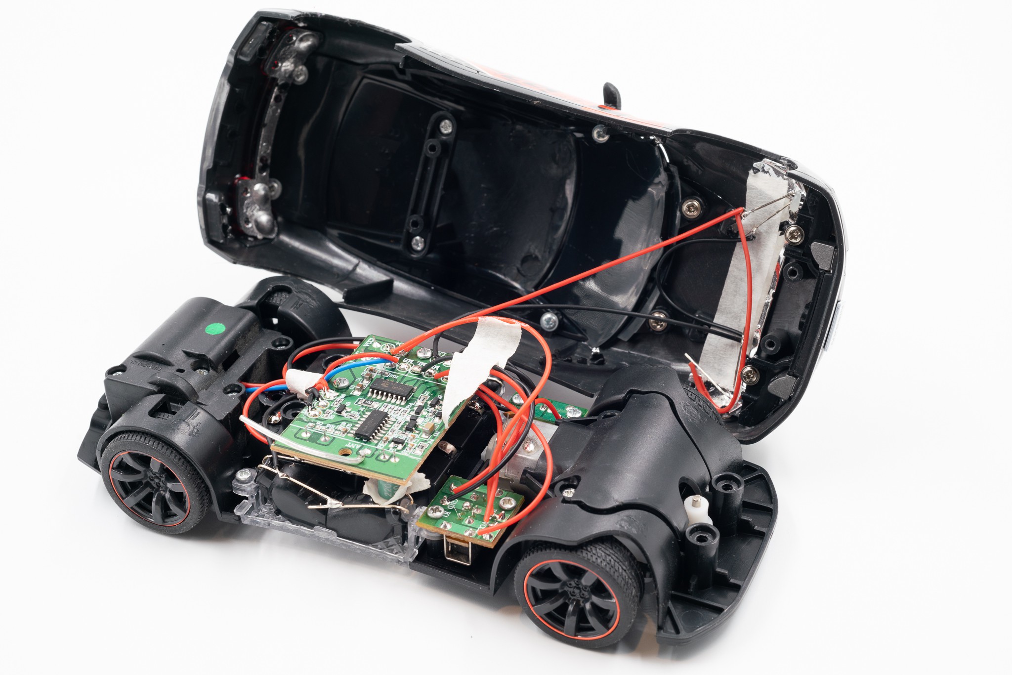
We picked a Fast Lane 1:24 RC Car. This car is prefect for this project, as it has all features that we are looking for, such as headlight and underglow LEDs with enough room to put our board inside.
-
2Taking the Car apart
![]()
![]()
![]()
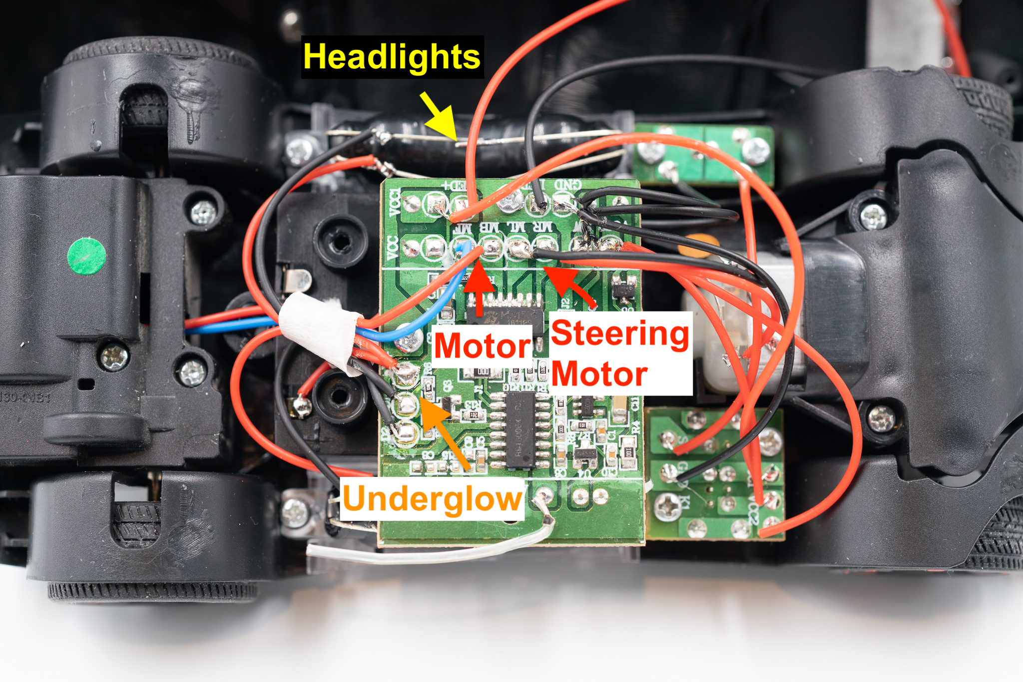
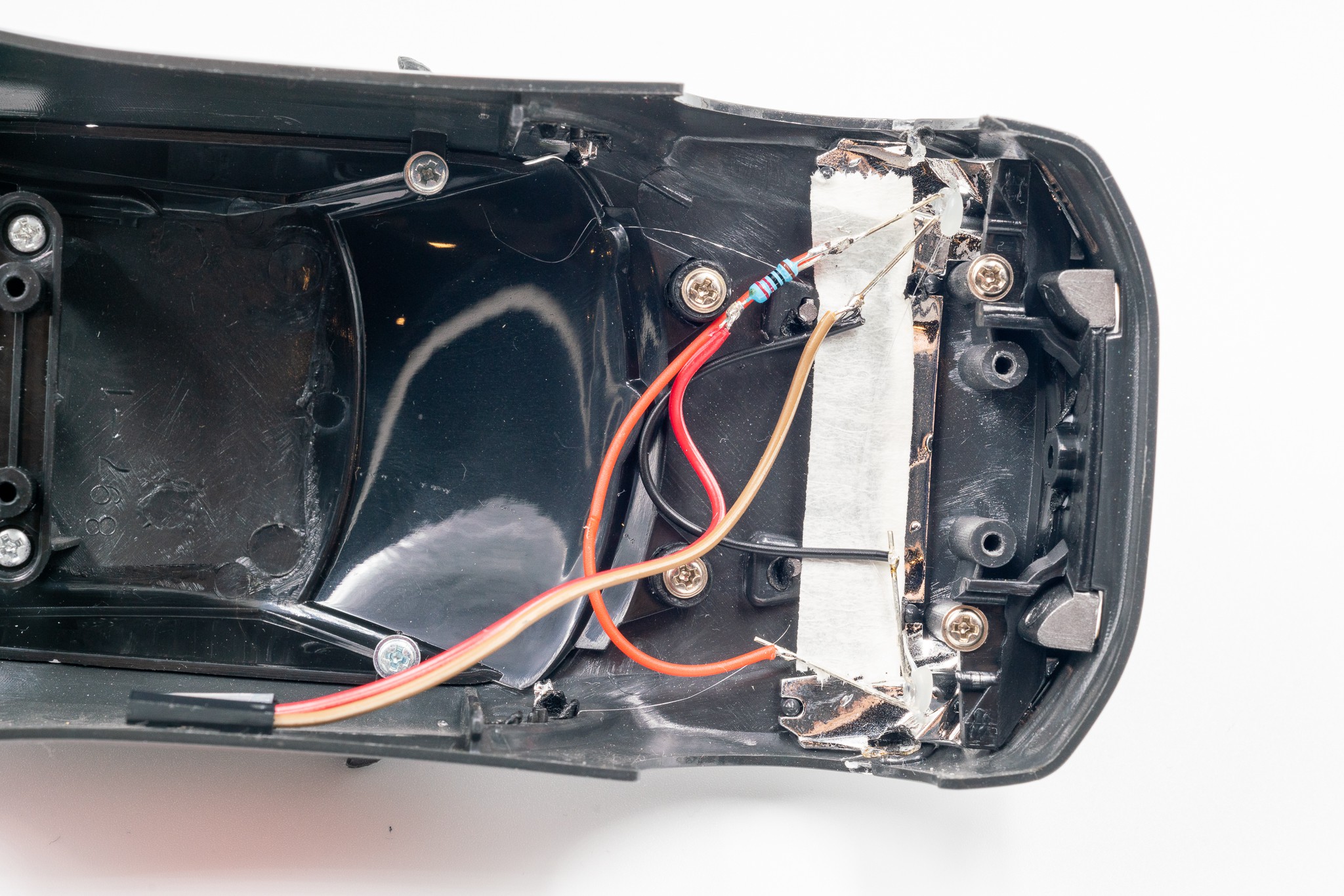
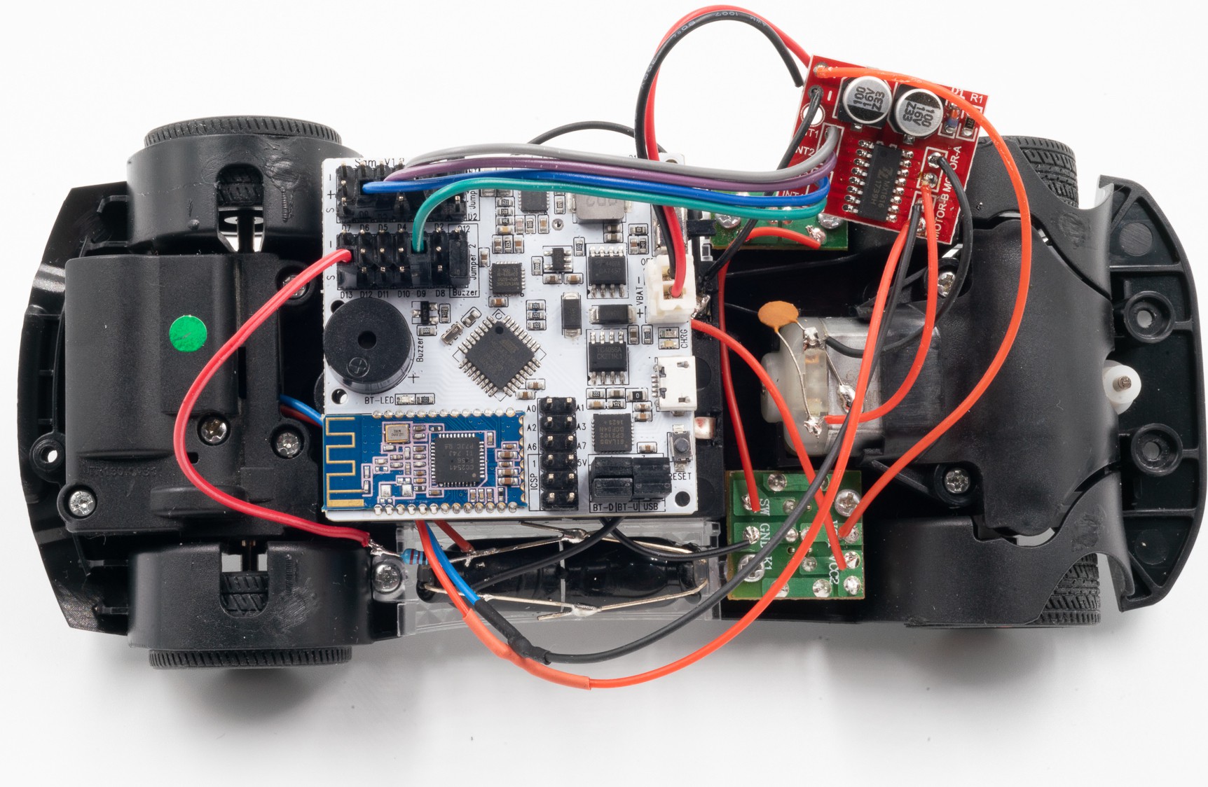
After taking it apart, identify the wires for LEDs and motors. The desoldering them off the board and replace them with Arduino board and motor drive module.
-
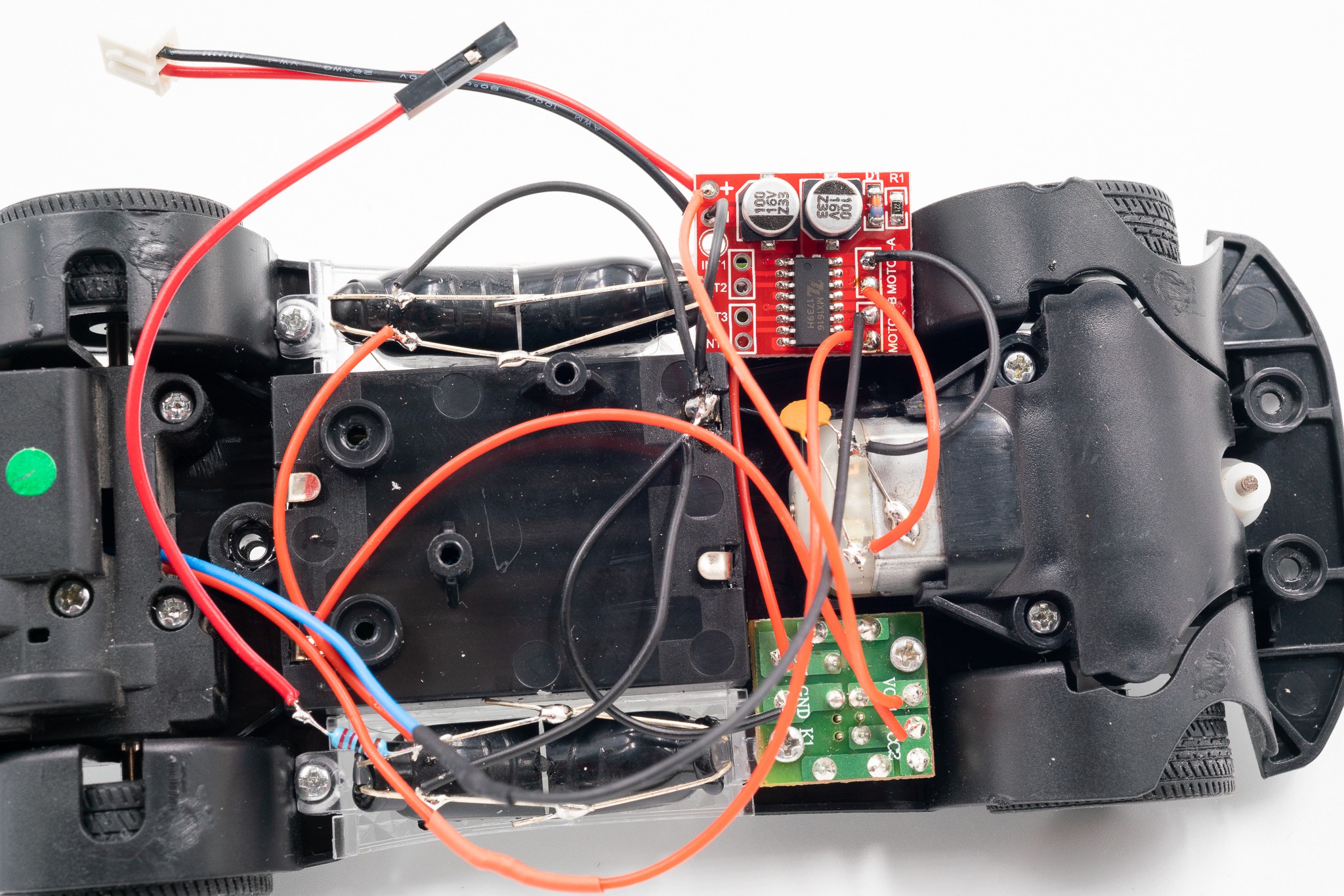
3Putting on the motor drive module
![]()
![]()
In this step, solder the steering motor to "MOTO A" and back motor to "MOTO B" on the motor driver module. Solder jumper wires to headlight & under-glow LEDs on both +ve & -ve side.
-
4Connecting to the SAM01 Arduino robotics board
![]()
![]()
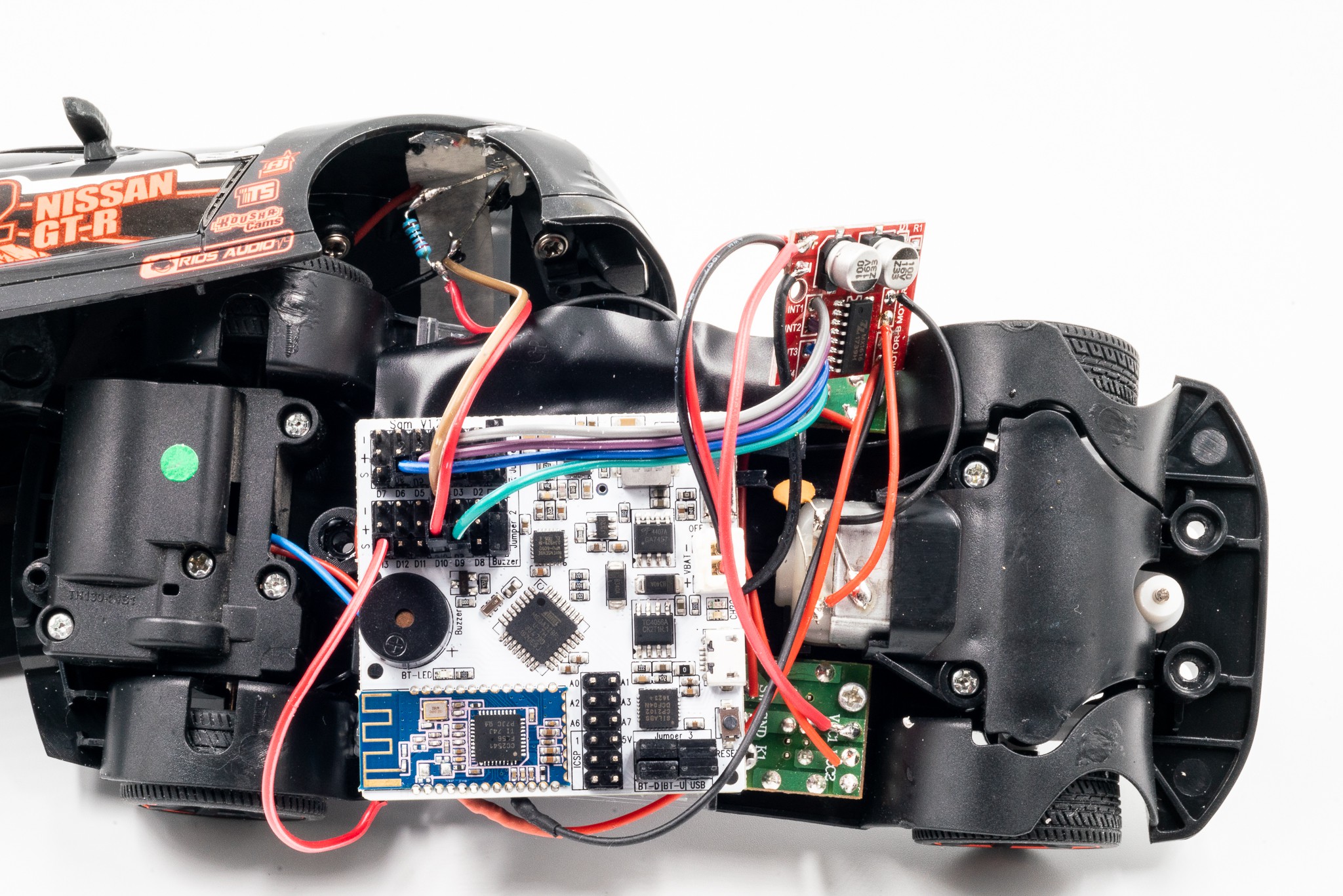
Putting on the SAM01 Arduino Robotics Board and connecting the jumper wires as following.
PIN 3 - INT1 for Motor A (Steering Motor)
PIN 5 - INT2 for Motor A
PIN 6 - INT3 for Motor B (Drive Motor)
PIN 9 - INT4 for Motor B
PIN 10 - Headlight LEDs
PIN 13 - Under-glow LEDs -
5Arduino Coding & Testing
Now it is time for testing all the connections. I have made Sam_RC_Car_Test.ino for ease of testing. Upload the ino file with Arduino IDE.
** Set board to "Arduino Nano" in Arduino IDE**
#define MA1 3 #define MA2 5 #define MB1 6 #define MB2 9 #define BOTTOM_LED 13 #define FRONT_LED 10 void setup() { // put your setup code here, to run once: Serial.begin(9600); pinMode(MA1, OUTPUT); pinMode(MA2, OUTPUT); pinMode(MB1, OUTPUT); pinMode(MB2, OUTPUT); pinMode(BOTTOM_LED, OUTPUT); pinMode(FRONT_LED, OUTPUT); } void loop() { // right analogWrite(MA1, 255); analogWrite(MA2, 0); // forward analogWrite(MB1, 150); analogWrite(MB2, 0); delay(3000); // left analogWrite(MA1, 0); analogWrite(MA2, 255); // stop analogWrite(MB1, 0); analogWrite(MB2, 0); delay(3000); // middle analogWrite(MA1, 0); analogWrite(MA2, 0); // backward analogWrite(MB1, 0); analogWrite(MB2, 255); delay(3000); // Testing LEDs digitalWrite(BOTTOM_LED, HIGH); digitalWrite(FRONT_LED, HIGH); delay(100); digitalWrite(BOTTOM_LED, LOW); digitalWrite(FRONT_LED, LOW); delay(100); } -
6Prepare for Blynk
After the connections are verified. We are ready to connect with Blynk through BLE.
First upload the file Sam_Blynk_RC_Car.ino with Arduino IDE.
#define MA1 3 #define MA2 5 #define MB1 6 #define MB2 9 #define BOTTOM_LED 13 #define FRONT_LED 10 //#define BLYNK_USE_DIRECT_CONNECT // You could use a spare Hardware Serial on boards that have it (like Mega) #include <SoftwareSerial.h> SoftwareSerial BLESerial(10, 9); // RX, TX #define BLYNK_PRINT Serial #include <BlynkSimpleSerialBLE.h> // You should get Auth Token in the Blynk App. // Go to the Project Settings (nut icon). char auth[] = "yourAuthToken"; bool turbo; void forward(int speed) { analogWrite(MB1, speed); analogWrite(MB2, 0); // Serial.println("Speed: "); // Serial.println(speed); } void backward(int speed) { analogWrite(MB1, 0); analogWrite(MB2, -speed); // Serial.println("back speed: "); // Serial.println(speed); } void right(int speed) { analogWrite(MA1, speed); analogWrite(MA2, 0); } void left(int speed) { analogWrite(MA1, 0); analogWrite(MA2, speed); } BLYNK_WRITE(V0) { int pinValue = param.asInt(); // assigning incoming value from pin V1 to a variable Serial.println(pinValue); if(pinValue >= 0) { if(turbo) forward(pinValue); else if (pinValue == 0) forward(0); else forward(pinValue * 0.7 + 30); } else { backward(pinValue * 0.7 - 30); } } BLYNK_WRITE(V2) { int pinValue = param.asInt(); // assigning incoming value from pin V1 to a variable //Serial.print("Left "); //Serial.println(pinValue); if(pinValue) left(255); else left(0); } BLYNK_WRITE(V3) { int pinValue = param.asInt(); // assigning incoming value from pin V1 to a variable //Serial.print("Right "); //Serial.println(pinValue); if(pinValue) right(255); else right(0); } BLYNK_WRITE(V1) { int pinValue = param.asInt(); // assigning incoming value from pin V1 to a variable if(pinValue) turbo = true; else turbo = false; } void setup() { // Debug console Serial.begin(115200); Serial.println("Waiting for connections..."); // Blynk will work through Serial // Do not read or write this serial manually in your sketch BLESerial.begin(9600); Blynk.begin(BLESerial, auth); pinMode(MA1, OUTPUT); pinMode(MA2, OUTPUT); pinMode(MB1, OUTPUT); pinMode(MB2, OUTPUT); forward(0); turbo = false; } void loop() { Blynk.run(); } -
7Setup Blynk
Copy the Auth Token back to Sam_Blynk_RC_Car.ino.
char auth[] = "yourAuthToken";![]()
-
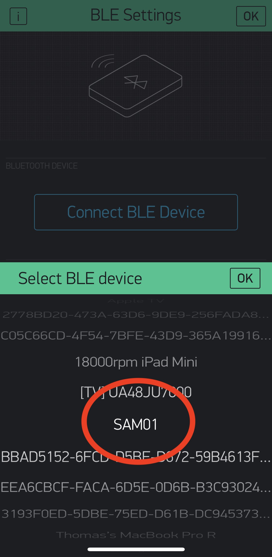
8Final Step - Connect and Start Playing
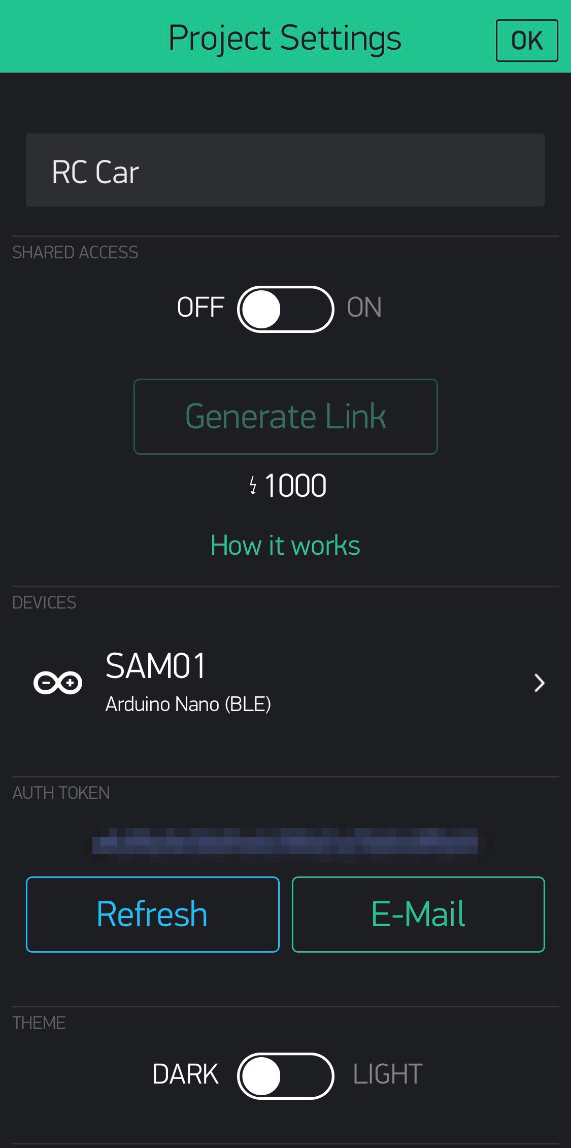
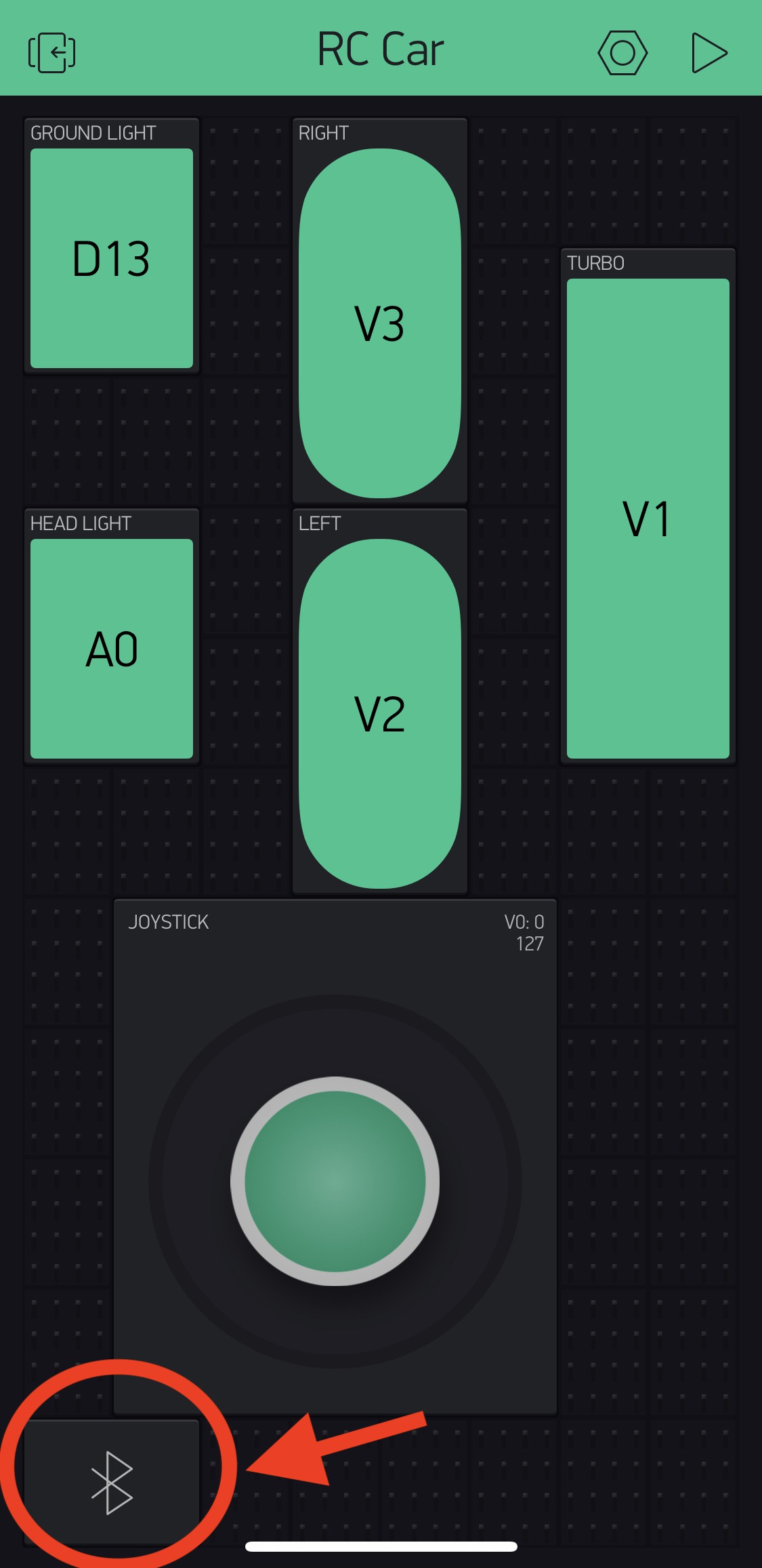
Turn on the RC Car's power and search for SAM01 in Blynk App by following the steps below
![]()
![]()
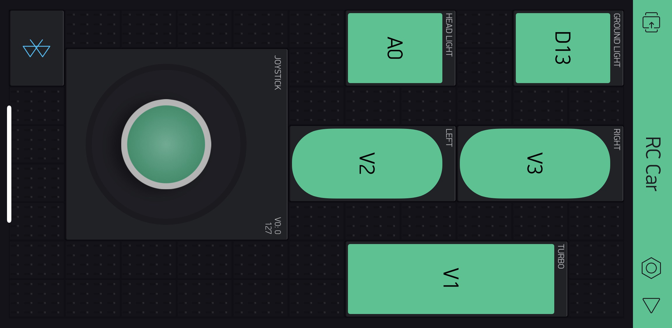
It is all set and ready to GO!!!
![]()
-
9Ready to GO!!
App Control Bluetooth (BLE) R/C Car with LEDs
Turn any remote car to an App Control Bluetooth (BLE) R/C Car and add extra control and sound


Discussions
Become a Hackaday.io Member
Create an account to leave a comment. Already have an account? Log In.