Roger
Roger-
Phoebe’s Nemesis: Floor Transitions
09/23/2018 at 18:39 • 0 commentsRight now Phoebe is running around on a very rough first draft of chassis design. It was put together literally in an afternoon in the interest of time. Just throw the parts together so we can see if the idea will even work. Well, it did! And I’m starting to find faults with the first draft chassis that I want to address on the next version for a much better thought-out design.
The first major fault is the lack of ground clearance. When I switched my mentality from the rough terrain capable Sawppy rover to a flat ground TurtleBot like Phoebe, I didn’t think the latter would need very much ground clearance at all. As a result, Phoebe’ battery pack hung between the driving wheels and caster, with only a few millimeters of clearance between the bottom of the battery tray and the ground.
![Phoebe Ground Clearance Flat]()
If I’m not climbing rocks, I asked myself, why would I need ground clearance?
Well, I’ve found my answer: my home has rooms with carpet, rooms with linoleum, and rooms with tile. The transition between these surfaces are not completely flat. They’re pretty trivial for a walking human being, but for poor little Phoebe they are huge obstacles. Driving across the doorway from carpet to linoleum would cause Phoebe to get stuck on its battery belly.
![Phoebe Ground Clearance Threshold]()
“More ground clearance” is a goal for Phoebe’s next chassis.
(Cross-posted to NewScrewdriver.com)
-
ROS Notes: Map Resolution
09/21/2018 at 21:11 • 0 commentsNow that I’m driving Phoebe around and mapping my house, I’m starting to get some first-hand experience with robotic mapping. One of the most fascinating bits of revelation concerns map resolution.
When a robot launches the Gmapping module, one of the parameters (
delta) dictates the granularity of the occupancy grid in meters. For example, setting it to 0.05 (the value used in TurtleBot 3 mapping demo) means each square in the grid is 0.05 meters or 5 cm on each side.This feels reasonable for a robot that roams around a household. Large objects like walls would be fine, and the smallest common obstacle in a house like table legs can reasonably fill a 5cm x 5cm cell on the occupancy grid. If the grid cells were any larger, it would have trouble properly accounting for chair and table legs.
![Low Resolution Sharp Map 5cm]()
So if we make the grid cells smaller, we would get better maps, right?
It’s actually not that simple.
The first issue stems from computation load. Increasing resolution drastically increases the amount of memory consumed to track the occupancy grid, and increases computation requirements to keep grid cells updated. The increase in memory consumption is easy to calculate. If we halve the grid granularity from 5cm to 2.5cm, that turns each 5cm square into four 2.5cm squares. Quadrupling the memory requirement for our occupancy grid. Tracking and maintaining this map is a lot more work. In my experience the mapping module has a lot harder time matching LIDAR scan data to the map, causing occasional skips in data processing that ends up reducing map quality.
The second issue stems from sensor precision. An inexpensive LIDAR like my unit salvaged from a Neato robot vacuum isn’t terribly precise, returning noisy distance readings that varies over time even if the robot and the obstacle are both standing still. When the noise exceeds map granularity, the occupancy grid starts getting “fuzzy”. For example, a solid wall might no longer be a single surface, but several nearby surfaces.
![High Resolution Fuzzy Map 1cm]()
As a result of those two factors, arbitrarily increasing the occupancy map resolution can drastically increase the cost without returning a worthwhile improvement. This is a downside to going “too small”, and it was less obvious than the downside of going “too large.” There’s a “just right” point in between that makes the best trade-offs. Finding the right map granularity to match robots and their tasks is going to be an interesting challenge.
(Cross-posted to NewScrewdriver.com)
-
Phoebe The Cartographer
09/20/2018 at 21:19 • 2 commentsOnce odometry calculation math in the Roboclaw ROS driver was fixed, I could drive Phoebe around the house and watch laser and odometry data plotted in RViz. It is exciting to see the data stream starting to resemble that of a real functioning autonomous robot! And just like all real robots… the real world does not match the ideal world. Our specific problem of the day is odometry drift: Phoebe’s wheel encoders are not perfectly accurate. Whether from wheel slippage, small debris on the ground, or whatever else, they cause the reported distance to be slightly different from actual distance traveled. These small errors accumulate over time, so the position calculated from odometry becomes less and less accurate as Phoebe drives.
The solution to odometry drift is to supplement encoder data with other sensors, using additional information can help correct for position drift. In the case of Phoebe and her TurtleBot 3 inspiration, that comes in courtesy of the scanning LIDAR. If Phoebe can track LIDAR readings over time and build up a map, that information can also be used to locate Phoebe on the map. This class of algorithms is called SLAM for Simultaneous Location and Mapping. And because they’re fundamentally similar robots, it would be straightforward to translate TurtleBot 3’s SLAM demo to my Phoebe.
There are several different SLAM implementations available as ROS modules. I’ll start with Gmapping because that’s what TurtleBot 3 demo used. As input this module needs LIDAR data in the form of ROS topic
/scanand also the transform tree published via/tf, where it finds the geometry relationship between odometry (which I just fixed), base, and laser. As output, gmapping will generate an “occupancy grid”, a big table representing a robot’s environment in terms of open space, obstacle, or unknown. And most importantly for our purposes: it will generate a transform mappingmapcoordinate frame to theodomcoordinate frame. This coordinate transform is the correction factor to be applied on top of odometry-calculated position, generated by comparing LIDAR data to the map.Once all the pieces are in place, Phoebe can start mapping out its environment and also correct for small errors in odometry position as it drifts.
SLAM achievement: Unlocked!
![Phoebe GMapping]() (Cross-posted to NewScrewdriver.com)
(Cross-posted to NewScrewdriver.com) -
Driving Miss Phoebe
09/19/2018 at 19:24 • 0 commentsThis Hackaday.io project page is primarily focused on the hardware, but because Phoebe is a project to explore ROS there's a significant software component as well. After chassis first draft was assembled, I dove into the software side.
Up on Github is a free ROS node for integrating Roboclaw motor controller module used on Phoebe. I encountered three problems while trying to get Phoebe moving. All three of these fixes have been submitted back to the original repository as pull requests.
Once Phoebe was moving reliably, I tried to integrate LIDAR data with odometry data generated by Roboclaw from reading motor encoders, but that unveiled another bug with odometry calculation.
This fix has also been submitted as a pull request.
If and when the pull requests are approved, the original repository will pick up those fixes. But until then, people using Roboclaw in ROS and encountering the same issues can clone my fork of it.
-
LIDAR Installation Completes First Draft
09/14/2018 at 18:09 • 0 commentsWith the motors connected to Roboclaw, their direction and encoder in sync, and PID values tuned, Phoebe can be driven around via ROS
/cmd_veltopic and report its movement via/odom. However, Phoebe has no awareness of its surroundings, which is where the LIDAR module comes in.Salvaged from a Neato robot vacuum (and bought off eBay), it is the final major component to be installed on Phoebe. Since this is a rough first draft, the most expedient way to install the device is to drill a few holes for M3 standoffs, and mount the module on top of them. This allows the module clear lines of sight all around the robot, while sitting level with the ground. It is also installed as close to the center of the robot as practical. I don’t know if a center location is critical, but intuitively it seems to be a good thing to have. We’ll know more once we start driving it around and see what it does.
By this point the rough draft nature of the project is very visible. The LIDAR spin motor sticks out below the module the furthest, and the motor inadvertently sits right on top of the Raspberry Pi’s Ethernet port, which is the tallest point on a Pi. Raising the LIDAR high enough so they don’t collide left a lot of empty space between the two modules. Which is not wasted at the moment, because the wiring mess is getting out of control and could use all the space it can occupy.
The next version should lay things out differently to make everything neater. In the meantime, it’s time to see if we can drive this robot around and watch its LIDAR plot. And once that basic process has been debugged, that should be everything necessary to enable ROS projects to give Phoebe some level of autonomy.
![Phoebe TurtleBot Stage 3 LIDAR]() (Cross-posted to NewScrewdriver.com)
(Cross-posted to NewScrewdriver.com) -
Phoebe Receives Raspberry Pi Brain After PID Tuning
09/13/2018 at 18:11 • 0 commentsOnce the motor’s spin direction was sorted out, I connected both encoders to verify A/B signals are in sync with motor direction. Again this is checked by commanding motor movement via Ion Studio software and watching the reported encoder value.
When wired correctly, encoder counter will increase when motor is commanded to spin in the positive direction, and decrease when motor spins negative. If hooked up wrong, the encoder value will decrease when the motor spins positive, and vice versa. The fix is simple: power down the system, and swap the A/B quadrature encoder signal wires.
Once the motor direction is verified correct, and encoder wires verified to match motor direction, we can proceed to the final phase of Roboclaw setup: determine PID coefficients for motor control.
PID tuning is something of a black art. Fortunately, while a perfect tune is very difficult to obtain, it’s not that hard to get to “good enough.” Furthermore, Ion Studio features an “Auto Tune” option to automatically find functional PID coefficients. During SGVHAK Rover construction we had no luck getting it to work and resorted to tuning PID coefficients manually. Fortunately, this time around Ion Studio’s automatic PID tuning works. I’m not sure what changed, but I’m not going to complain.
Once PID coefficients have been written to Roboclaw NVRAM, we no longer need to use the Windows-based Ion Studio software. From here on out, we can use a Raspberry Pi to control our motors. The Pi 3 was mounted so its microSD card remains accessible, as well as its HDMI port and USB ports. This meant trading off access to GPIO pins but we’re not planning to use them just yet so that’s OK.
Software-wise, the Raspberry Pi 3’s microSD card has a full desktop installation of ROS Kinetic on top of Ubuntu Mate 16.04 compiled for Raspberry Pi. In addition to all the Robotis software for TurtleBot 3, it also has a clone of the ROS control node, as well as a clone of the Neato LIDAR control node.
The wiring is not very neat or pretty but, again, this is just a rough first draft.
![Phoebe TurtleBot Stage 2 Encoder Pi]()
(Cross-posted to NewScrewdriver.com)
-
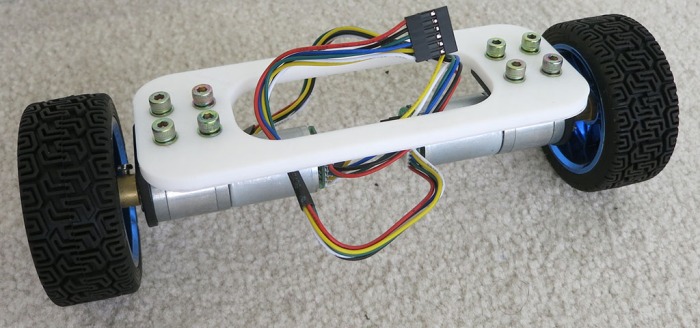
Establish Motor Directions
09/12/2018 at 17:15 • 0 commentsThe first revision of Phoebe’s body frame has mounting points for the two drive wheels and the caster wheel. There are two larger holes to accommodate drive motor wiring bundle, and four smaller holes to mount a battery tray beneath the frame. Since this is the first rough draft, I didn’t bother spending too much time over thinking further details. We’ll wing it and take notes along the way for the next revision.
![Phoebe Frame First Draft.PNG]()
After the wheels were installed, there was much happiness because the top surface of the frame sat level with the ground, indicating the height compensation (for height difference between motorized wheels and caster in the back) was correct or at least close enough.
Next, two holes were drilled to mechanically mount the Roboclaw motor control module. Once secured, a small battery was connected plus both motor drive power wires. Encoder data wires were not connected, just taped out of the way, as they were not yet needed for the first test: direction of motor rotation.
![Phoebe TurtleBot Stage 1 PWM]()
The Roboclaw ROS node expects the robot’s right side motor to be connected as Motor #1, and the left as Motor #2. It also expects positive direction on both motors to correspond to forward motion.
I verified robot wiring using Ion Studio, the Windows-based utility published by the makers of Roboclaw. I used Ion Studio to command the motors via USB cable to verify the right motor rotates clockwise for positive motion, and the left motor counter-clockwise for positive motion. I got it right on the first try purely by accident, but it wouldn’t have been a big deal if one or both motors spun the wrong way. All I would have had to do is to swap the motor drive power wires to reverse their polarity.
(Cross-posted to NewScrewdriver.com)
-
Test Frame To Help Arrange Phoebe’s Wheels
09/11/2018 at 17:27 • 0 commentsSince Phoebe will be a TurtleBot variant built out of stuff already in my parts bin, these parts won’t necessarily fit together well. The first thing to do is to figure out how to make the wheels work together. A simple test frame will mount Phoebe’s two drive wheels and see how they cooperate. And besides, building a two-wheel test chassis is how I’ve started many robot projects and that’s worked out well so far. So now let’s make another one to follow in the grand tradition of two wheel test chassis built to test parts going into SGVHAK Rover and Sawppy Rover.
![Phoebe TurtleBot Two Wheel Test Frame]()
For Phoebe, this simple test chassis established the following:
- I used a caliper to measure wheel mounting bracket dimensions, and they are accurate enough to proceed. They are spaced the correct distance apart, and their diameter is large enough for M4 bolts to slide through without being so large that the resulting wheel wobbles.
- The 5mm thick slender connecting members are too weak. The next frame will have greater thickness and generally beefier structure.
- I wanted a 20cm track. (Left-right distance between wheel centers.) I measured the dimensions for my wheel assembly but the measurements were a little off. Now I know how much to adjust for the next frame.
- And most importantly: this frame allowed direct comparison of drive wheel resting height against caster wheel height. They were both awkward shapes to measure with a ruler so having the flat surface of a frame makes the measurement easier. Their relative height difference needs to be accounted for in the next frame in order to have a robot body that is level with the ground.
(Cross-posted to NewScrewdriver.com)
-
Cost to Build Phoebe From Scratch
09/10/2018 at 17:13 • 0 commentsI chose components for Phoebe (“PB” or Parts Bin) TurtleBot because they were already available to me in one context or another. But not everyone has the same stuff in their own hoard. As an exercise for completeness, below is an estimate of what it would cost to build Phoebe if parts had to be purchased. Naturally, any parts already on hand can be subtracted from the cost. (The expected audience here is likely to have at least a Raspberry Pi 3 and battery to spare.)
- Onboard computer: A Raspberry Pi 3 with microSD card, case, and DC power supply will add up to roughly $50.
- Laser scanner: LIDAR salvaged off Neato robot vacuum cleaners are on eBay with “Buy It Now” prices of $50-$75 at time of this writing. People living in a major metropolis like Los Angeles can find entire Neato vacuums on Craigslist in a similar price range.
- Motor controller: A Roboclaw with 7A capacity can be purchased directly from the manufacturer for $70. It is overkill for this project, but it was their entry-level product and it was already on hand. Lower-cost alternatives probably exist.
- Gearmotor + Encoder + Wheel: Buying the motors I’m using from Pololu would be $35 each without bracket or wheel. However, similar units including mounting bracket and wheel are available on Amazon for $20 each.
- Caster wheel: A caster wheel can be salvaged off a piece of broken furniture for free. If you have to buy a caster, don’t pay more than $3.
- Battery: The battery pack I’m using are available for $25 each, but it’s far more battery than necessary for this project. A far smaller pack for $10-15 would be sufficient.
Sum total: $238, which still does not include the following:
- 3D printer filament.
- Electrical connectors and wiring.
- Bolts, nuts, and other assembly hardware.
But given room for improvement (cheaper motor controller and battery) a whole package to build Phoebe from scratch should be possible for under $250, less than half of a TurtleBot 3 Burger.
(Cross-posted to NewScrewdriver.com)
-
New Project: Phoebe TurtleBot
09/09/2018 at 17:31 • 0 commentsWhile my understanding of the open source Robot Operating System is still far from complete, I feel like I’m far enough along to build a robot to run ROS. Doing so would help cement the concepts covered so far and serve as an anchor to help explore new areas in the future.
Sawppy Rover is standing by, and my long-term plan has always been to make Sawppy smarter with ROS. Sawppy’s six-wheeled rocker-bogie suspension system is great for driving over rough terrain but fully exploiting that capability autonomously requires ROS software complexity far beyond what I could handle right now. Sawppy is still the goal for my ROS journey, but I need something simpler as an intermediate step.
A TurtleBot is the official ROS entry-level robot. It is far simpler than Sawppy with just two driven wheels and restricted to traveling over flat floors. I’ve been playing with a simulated TurtleBot 3 and it has been extremely helpful for learning ROS. Robotis will happily sell a complete TurtleBot 3 Burger for $550. This represents a discounted bundle price less than the sum of MSRP for all of its individual components, but $550 is still a nontrivial chunk of change. Looking over its capabilities, though, I’m optimistic I could implement critical TurtleBot functionality using parts already on hand.
![Components for parts bin turtlebot phoebe]()
- Onboard computer: This one is easy. I have several Raspberry Pi 3 sitting around I could draft into the task, with all necessary accessories like a microSD card, a case, and power supply.
- Laser scanner: Instead of the Robotis LDS-01, I’ll use a scanning LIDAR salvaged from a Neato robot vacuum that I bought off eBay for experimentation. Somebody has already written a driver package to report its data as a ROS
/scantopic and I’ve already verified it sends data that the ROS visualization tool RViz can understand. - Motor controller: Robotis OpenCR is a very capable board with lots of expansion capabilities, but I have a RoboClaw left from SGVHAK Rover (JPL Open Source Rover) project so I’ll use that instead. Somebody has already written a driver package to accept commands via ROS topic
/cmd_veland report motion via/odom, though I haven’t tried it yet. - Gearmotor + Encoder: TurtleBot 3 Burger’s wheels are driven by Robotis Dynamixel XL430-W250-T serial bus servos via their OpenCR board. Encoders are critical for executing motor commands sent to
/cmd_velcorrectly and for reporting odometry information via/odom. Fortunately some gearmotor+encoder from Pololu are available. These were formerly SGVHAK Rover’s steering motors, but after one of them broke they were all replaced with beefier motors. I’m going to borrow two of the remaining functioning units for this project. - Wheel: Robotis has a wheel designed to bolt onto their servos, and they have mounting hardware for their servos. I’m going to borrow the wheel and mounting hardware from a self-balancing robot toy gathering dust on a shelf. (Similar but not identical to this one.) That toy didn’t have encoders on its motors, but they have the same mounting points and output shaft as the Pololu gearmotor so it was an easy swap. The third wheel, a free wheeling caster, was salvaged from a retired office chair.
- Chassis hardware: Robotis has designed a modular system (like an Erector Set) for building robot chassis like their TurtleBot variants. As for me… I have a 3D printer and I’m not afraid to use it.
- Battery: I'll be borrowing Sawppy’s 5200 mAh battery pack.
This forms the roster for my TurtleBot variant, with an incremental component cost of $0 thanks to the parts bin. “Parts Bin TurtleBot” is a mouthful to say and not a very friendly name. I looked at its acronym “PB-TB” and remembered R2-D2’s nickname “Artoo”. So I’m going to turn “PB” into Phoebe.
I hereby announce the birth of my TurtleBot variant, Phoebe!
(Cross-posted to NewScrewdriver.com)
Phoebe TurtleBot
DIY variant of ROS TurtleBot for <$250 capable of simultaneous location and mapping (SLAM)


 (Cross-posted to
  (Cross-posted to