-
Results So Far...
10/01/2018 at 02:55 • 0 commentsI've had two bins fitted with a Bin Monitored for 10 days or so, one is fitted to my blue (recycling) bin, and another on my black (general rubbish) bin.
Unfortunately with the blue bin monitor I believe I broke the accelerometer whilst debugging my code, or maybe it was one from the duff AliExpress batch and never really worked well. Either way it doesn't appear fully functional and often "latches" in a certain orientation.
The Black bin unit has been running in high power mode, sending data via WiFi ever minute, so the battery has been going flat regularly, and annoyingly I fitted the battery monitor resistors the wrong way around so it always reports a full battery!.
I've not as yet deployed a unit to my green bin, this is still on my desk for firmware development.
Dashboard:
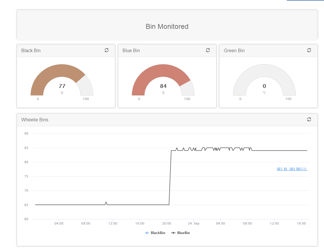
I created a little dashboard in Tinamous so I could see how full my bins were. I'm sure you'll appreciate the blue line used for the black bin, and black line used to indicate the blue bin, this is some unfortunate default colours applied to the chart which plots the primary field (PercentageFull) for any device tagged "BinMonitored".
![]()
Bin Opened Notifications
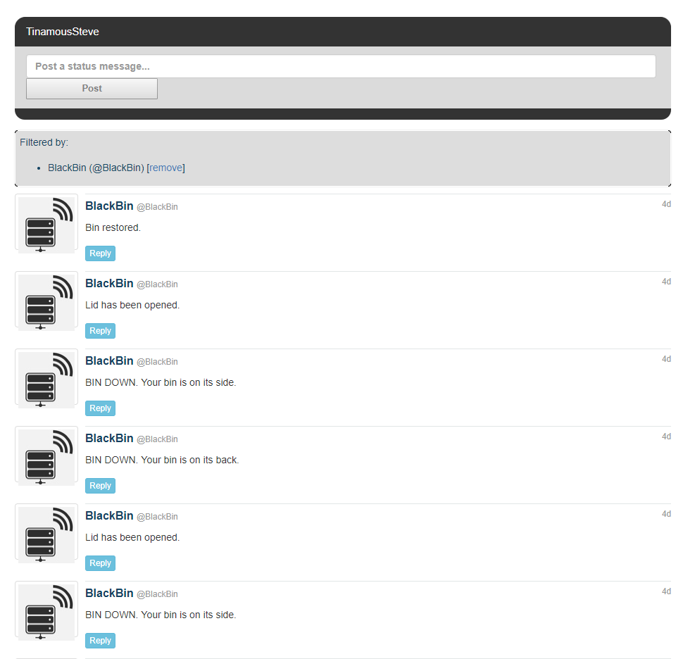
The screen shot below shows the Tinamous timeline for the black bin monitor which posts notifications when it detects the lid is opened or it thinks the bin has fallen over (in this case, it is me removing the unit to replace the battery). Tinamous can be configured to send a text message, email or other notification when a status post is published containing certain text, so we can use "Lid has been opened" to trigger the sending of a text message to myself so I know a parcel may have been left for me.
![]()
Rubbish Level Tracking
The rubbish level sensor has work well, unfortunately the chart is not so interesting, as you can see a week ago my blue bin was full!
![]()
I was a little unsure how the rubbish level in the black bin would register as I use black bags for my rubbish in that bin, however the IR sensor appears to work well with that, the chart below shows when I added some more rubbish to my black bin...
![]()
Environmental Monitoring
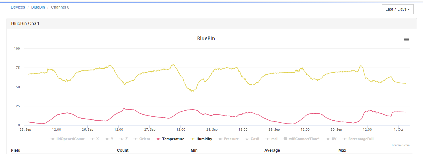
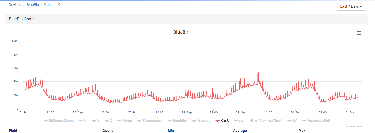
I didn't fit a BME680 to the black bin unit as I wanted to asses the impact on battery life without that sensor, however the blue bin sensor has been working well, I'm not sure it's any use for bin monitoring, but it does make a nice outside "weather" sensor.
![]()
![]()
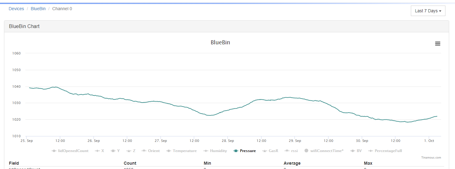
I still have no idea if the VOC gas sensor will be any use for Bin Monitored, I've not yet deployed a unit into my green (compost) bin which might be a little more interesting. However Bin Monitored may be suited to a garage monitor system, attached to the door it could detect of the car is in the garage, if the garage door is up, and using the gas sensor, if their are any dangerous vapours in the atmosphere, for example if the car was leaking petrol, or if the engine was running with the doors closed. (I don't know how it would respond to CO, and I've got no intention of finding out!).
![]()
Overall I'm pleased with how well it is working, especially for a first version. Battery life is a problem, but I'm currently running both my units in a fairly high frequency wake and send pattern so it should improve.
-
Low Power - I Stuffed Up!
10/01/2018 at 02:22 • 0 commentsThe ESP8266 features a very nice deep sleep mode where the entire module sleeps, consuming only nano-amps until woken, either by the on-board RTC or some external factor, this is ideal for Bin Monitored, it could sleep all day long, waking only occasionally to send an "Im still alive" signal and how full the bin is, or be woken by the accelerometer if something interesting happens.
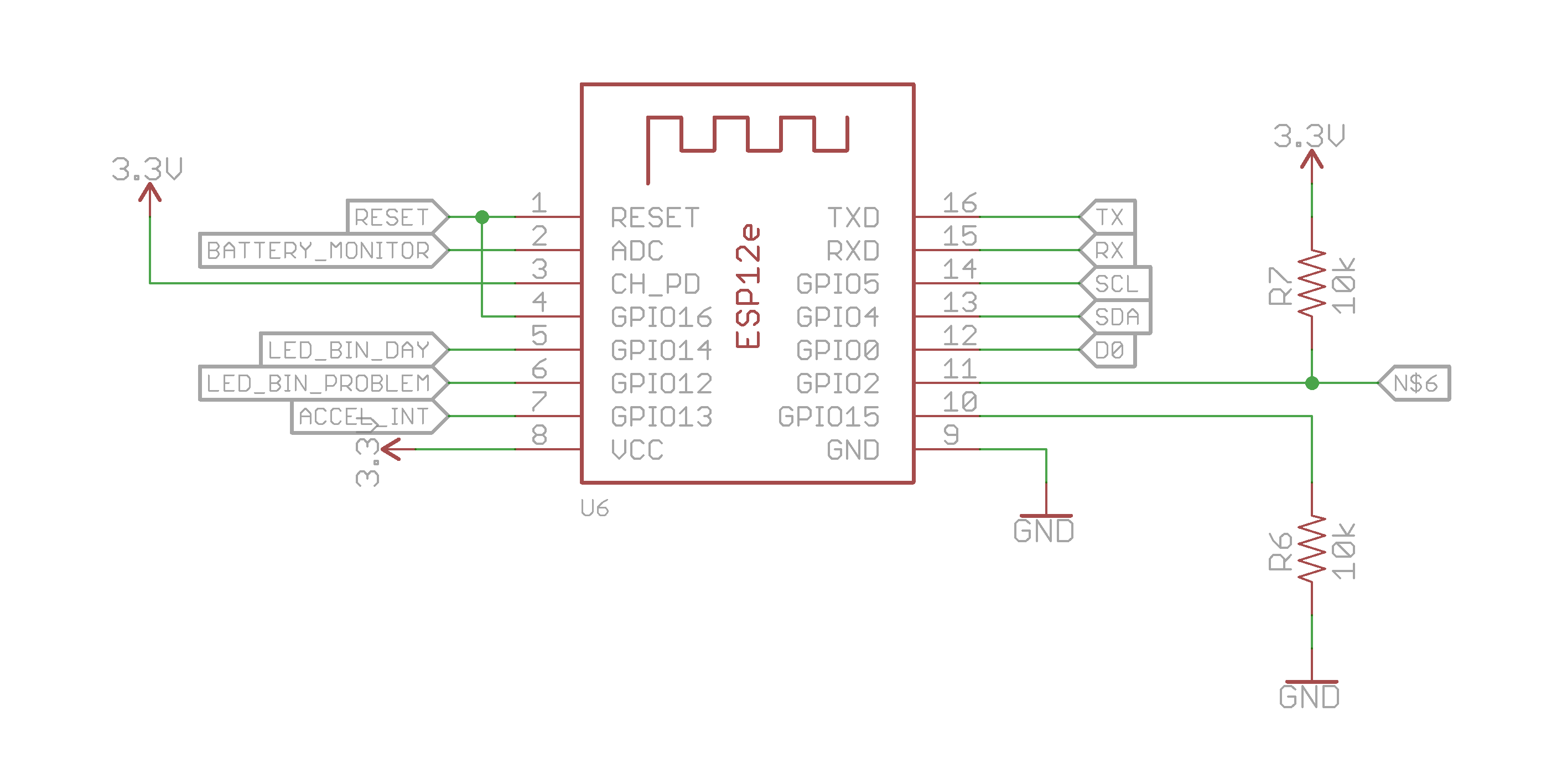
This was my first time trying to use the ESP12 in low power mode and I got a few things wrong. Quite a few things...
I connect GPIO16 to the reset pin to allow the RTC to wake the ESP when in deep sleep mode as per the datasheet, this works well....
![]()
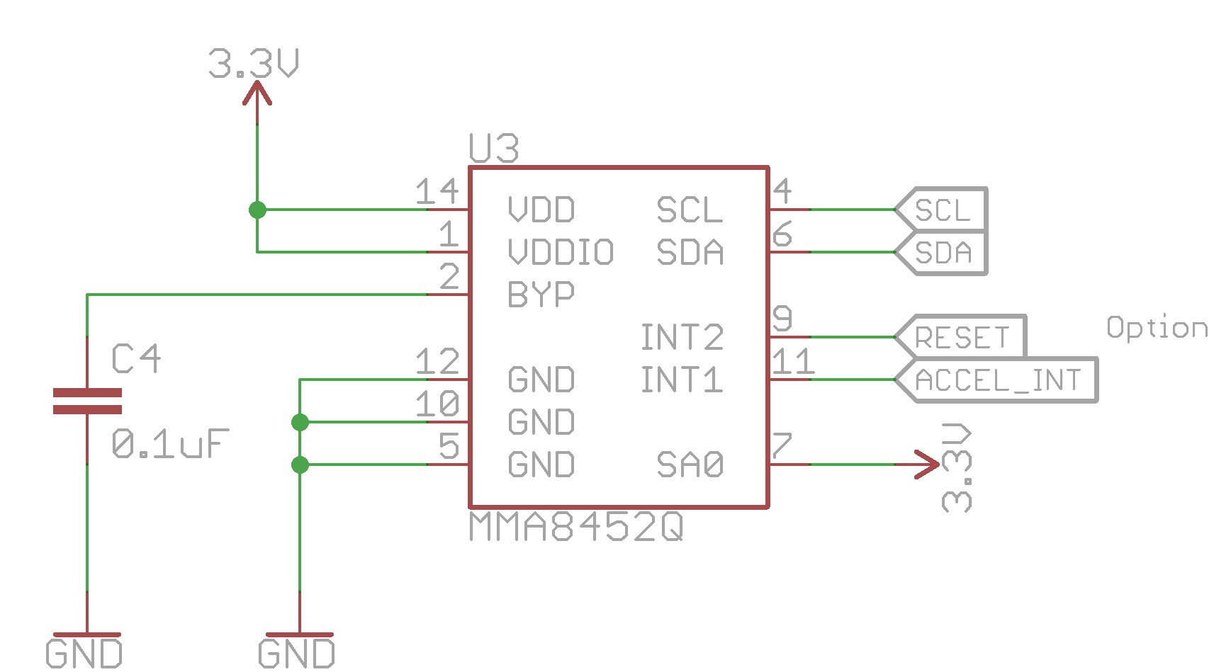
So I figured I'd do the same with the accelerometer. I could program INT2 to go low and reset the ESP, so waking it when an interesting event occurred...
![]()
Yep, you guessed the obvious problem, the MMA8452 latches the interrupt output, it's not pulsed and is only cleared when you read the appropriate register, so if INT2 ever gets asserted it will keep the ESP in a reset state. Not so great.
I had also planned to route this via a 0R resistor link so I could remove it if my plan failed. I forgot that! Fortunately as long as the firmware never configures INT2 it doesn't affect the processor, but I'm only ever one bad firmware deployment away from making a brick, one square inch in size :-)
Going forward, I can either modify the circuit so the asserted interrupt causes only a pulse on the reset line, or try and use the enable pin (pin 3 - CH_PD) on the ESP to wake the device.
Mostly Sleeping...
However for now I have no way to wake the ESP from deep sleep when an interesting even occurs, so instead I sleep the ESP for a short time (1 minute in this case), when it wakes the startup routine checks the ACCEL_INT pin (GPIO13), if it is asserted then the accelerometer has registered an event (lid opened) and further investigation is needed.
The accelerometer is configured so that an interrupt is generated if motion is detected in the Y axis. When the lid is opened the accelerometer is orientated such that acceleration due to gravity is through the Y axis (it's normally through the Z giving -1G). This "motion" caused by gravity is enough to tell the lid has been opened. Additionally the sample rate of the accelerometer is slowed down to save on power.
Detecting if the bin has fallen over is a little more tricky so I decided to do this detection only on occasional intervals and keep the interrupt strictly for the lid being opened.
The initial part of setup code for the ESP is below. It checks to see if the accelerometer has interrupted, then it checks the time to see if the bin level / environment should be checked and then updates the fake RTC to track time. If no action is required the ESP goes back into a deep sleep as fast as possible. This takes a few hundred milliseconds and still contains (as you can see) a lot of debugging code!
void setup() {
  pinMode(ACCEL_INT, INPUT_PULLUP);

  pinMode(BIN_DAY_LED, OUTPUT);
  digitalWrite(BIN_DAY_LED, LOW);

  pinMode(STATUS_LED, OUTPUT);
  digitalWrite(STATUS_LED, LOW);

  // TODO: Only use serial during debugging.
  Serial.begin(115200);
  Serial.println("");
  Serial.println("====================================================");

  bool shouldSleep = true;

  Wire.setClock(400000);
  Wire.begin();

  // Read the configuration early.
  readConfiguration();

  // Check accelerometer interrupt to see
  // if something interesting has happened.
  if (hasAccelerometerInterrupt()) {
    // Handle accelerometer event...
    // most likely lid opened.
    // Motion setting lost when accelerometer is initialised.
    shouldSleep = false;
    lidOpenedCount++;
    // Cap at 100 to keep the number within a byte
    // so we don't overflow to 0.
    if (lidOpenedCount>100) {
      lidOpenedCount = 100;
    }
    // Only connect/send on the first open.
    shouldConnect = lidOpenedCount == 1;
    lidOpened = true;
  } else {
    // Lid closed, reset the counter.
    lidOpenedCount = 0;
  }

  // read the RTC value from EEPROM, update it based on wake interval
  // then write it back to keep track of time in a really
  // not very good way...
  readRtc();
  updateRtc();
  writeRtc();

  // Check to see if the bin status should be checked.
  // this happens on a periodic interval.
  if (shouldCheckBin()) {
    shouldSleep = false;
  }

  // Check if the bin status should be sent
  // again, this happens periodically.
  if (shouldUploadStatus()) {
    shouldSleep = false;
    shouldConnect = true;
  }

  // If nothing to do put the micro back to sleep
  // as soon as possible to
  if (shouldSleep) {
    Serial.println("Nothing to do. Sleeping.");
    deepSleep();
    // ESP will be reset to wake up so nothing after this happens.
  }
The ESP is woken from deep sleep once per minute for two reasons, the first is that Bin Monitored features an LED to indicate if it is bin collection day (In Cambridge different bins are collected weekly, one week the black bin, the next the blue and green bins). So to make the LED reasonably responsive (if you can call 1 minute delay responsive!), the ESP is woken every minute to detect of the lid is opened and notify me if it is bin day. As it turns out the enclosure obscures the LED so it's of little use.
The second reason is to keep an on-board fake RTC running, every time the ESP is woken an on-board counter is incremented and stored in EEPROM to track time. This is used to determine if the ESP should check the bin contents and to track if the day is bin day.
To try and avoid wearing out the EEPROM I've used a range of addresses for hour and minute storage based on the day/hour and minute, rather unusually this RTC uses a day value of 0 for bin day, and then counts only to the bin collection interval, in this case 14, when it resets back to 0. This saves tricky days per month calculation and tracks bin collection days rather than day of the month.
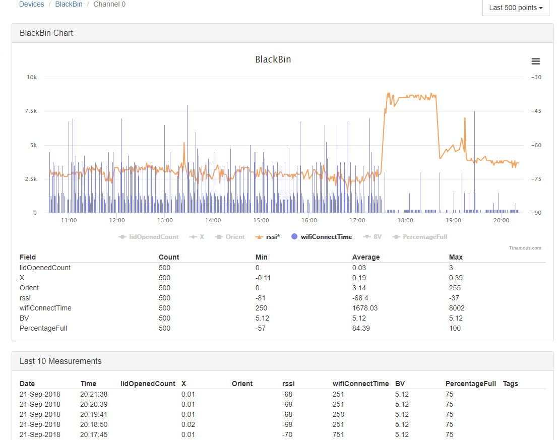
WiFi connectivity is kept to a minimum, I've used MQTT as transport connecting to the Tinamous MQTT server to reduce the overhead at the transport layer, perhaps the biggest gain in reducing the WiFi time was when I improved my home WiFi access point.
The blue series is time for the WiFi to connect, orange is RSSI. You can clearly see when I replaced my WiFi access point, connection time is typically 250ms now (which is currently the minimum time the device can connect in due to a 250ms delay in my code!).
![]()
Battery life is still an issue, despite the cheap CR123A's claiming 2200mAH, they (oddly enough) only store about the same as the expensive CR123As, about 650mAH, which in sleep mode should be enough for over 3000 hours, or about 4 months. Ideally I would have liked years rather than months, but for now the sleep power consumption is to high.
The chart below shows the battery voltage (approx) Blue Bin Bin Monitored, it had the battery replaced on the 22 September, so far it's made 9 days so far, however it is sending data every 10 minutes rather than every day which doesn't help!
![]()
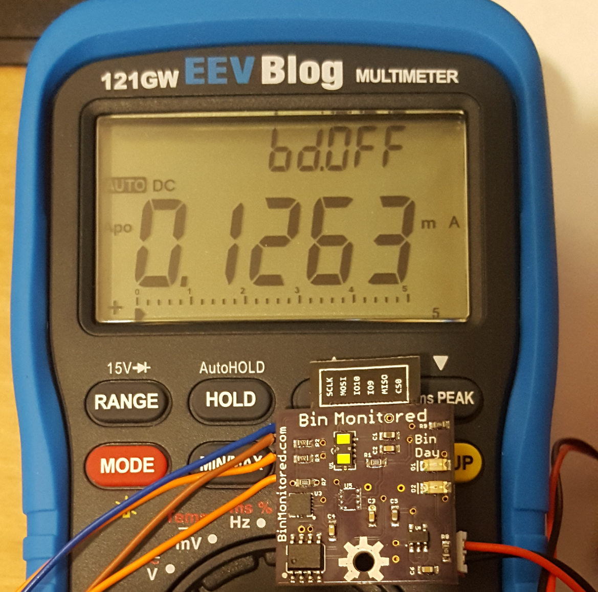
Deep sleep power consumption is about 10x what I had aimed for. More work to be done!...
![]()
-
Enclosure - Quality Product, defiantly not a bomb...
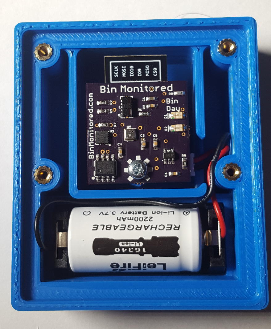
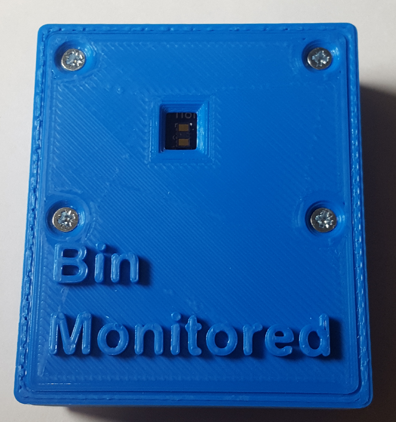
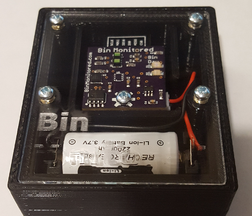
10/01/2018 at 01:26 • 0 commentsAfter a number of tries I finally settled on a 3D printed enclosure. This design has an outer lip so either a 3D printed lid can sit inside or a 3mm acrylic can, then a 3D printed lid on top of that. I've used heatfit M2.5 brass inserts to allow the lit to be removed easily to recharge/replace the battery.
![]()
With this lid. This isn't water proof as the hole in the lid goes directly to the PCB.
![]()
Alternative acrylic lid, you can see the PCB here doesn't have the BME680 fitted, I was trying a few variants to try and reduce power. The acrylic made no noticeable affect on the IR distance sensor, but provides a nice splash resistant covering. With this design I've created a larger lid to go over the top. As much as I like seeing inside, it may well look very suspicious to somebody else!
![]()
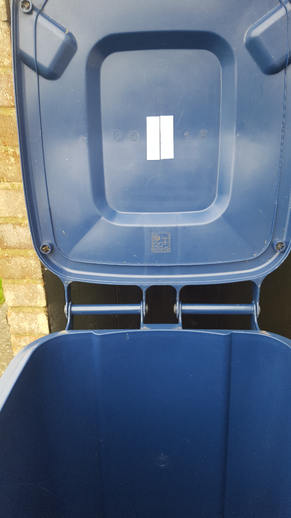
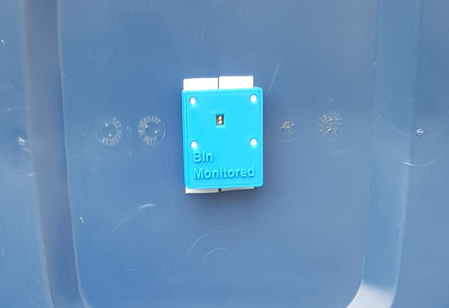
One of my concerns with Bin Monitored is it surviving the bin being emptied and then pressure washed clean. I'm in no hurry to find this out so opted to mount the Bin Monitored in my bins with Velcro. I cleaned the bin lid first with IPA to ensure the Velcro had a good surface to attach to.
![]()
I attached the other side of the Velcro to the back of the Bin Monitored enclosure and mounted the unit. This allows me to easily remove it to replace the battery and to remove it on bin days.
![]()
My other concern was that the waste collectors may mistake the device for an explosive device, we recently had a bomb scare in Cambridge city caused by a students improvised air quality monitor, I don't want a repeat of that so removing the device before rubbish collection works well!!!
-
AliExpress Special Accelerometers
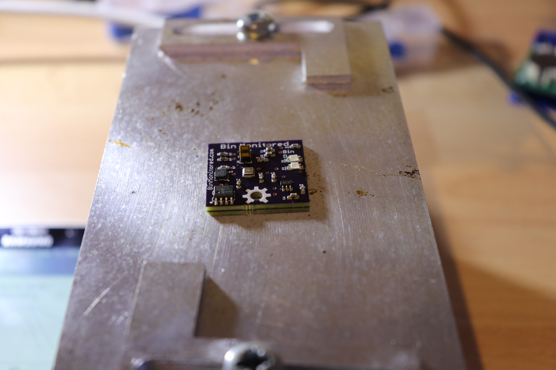
10/01/2018 at 01:09 • 0 commentsAs I described in my previous build log, I messed up on the first PCB, however I reworked this to correct my mistake, but when I powdered the board up it was tripping the current limit on my bench PSU (set to 100mA), I assumed (incorrectly) I had messed up the distance sensor when I rotated it. As it turns out, the accelerometer was faulty.
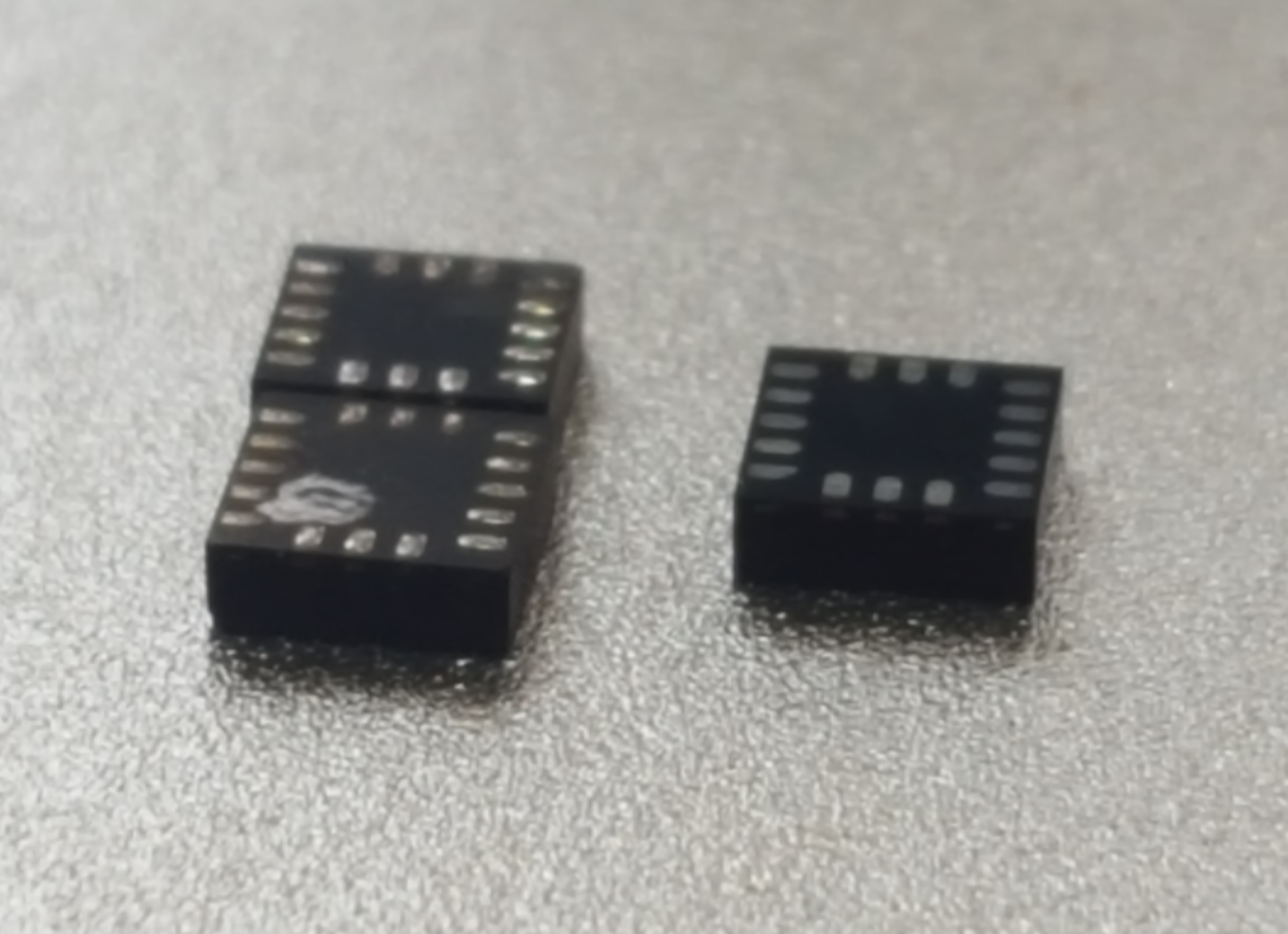
Moments after sending the files to OSH Park for this project I went to order the parts only to discover the accelerometer I used was out of stock everywhere. I knew I had one in my parts bins but I wanted more. Fortunately, or unfortunately as the case should be, I managed to source 20 from a seller on AliExpress. I took no notice when assembling the first PCBs to the state of the pads on the accelerometer, but after some fault finding I decided to take a closer look. Photos below with AliExpress sources accelerometers on the left, and the new one i had from Farnell.
![]()
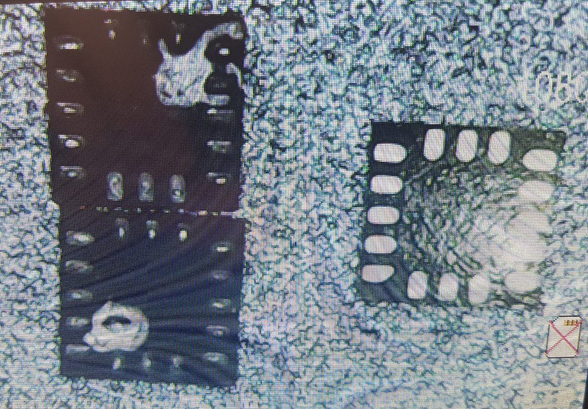
As seen through a little microscope...
![]()
The accelerometers have clearly been used and then removed, they were repackaged in tape to look original, I got lucky on the second one, but the first never worked, and to make matters worse, I found a stash of 10 new ones when I went to assemble a few more boards so I didn't even need the ones I ordered from AliExpress in the first place!
-
PCB Assembly.
10/01/2018 at 00:53 • 0 commentsBefore:
![]()
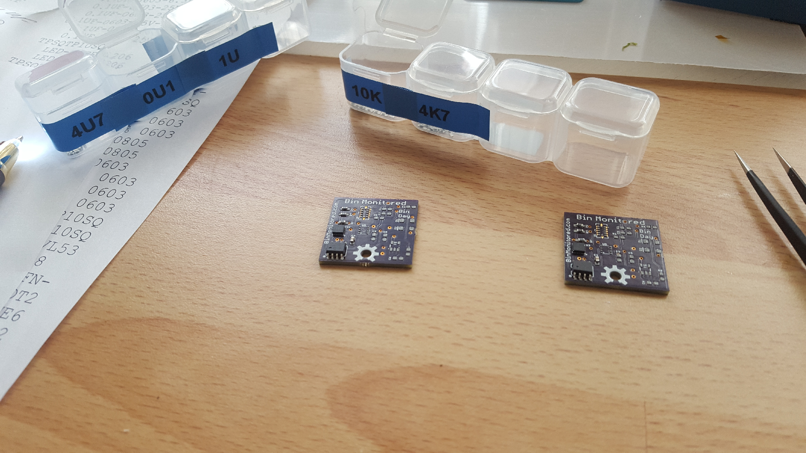
After (I only made up 2 boards initially):
![]()
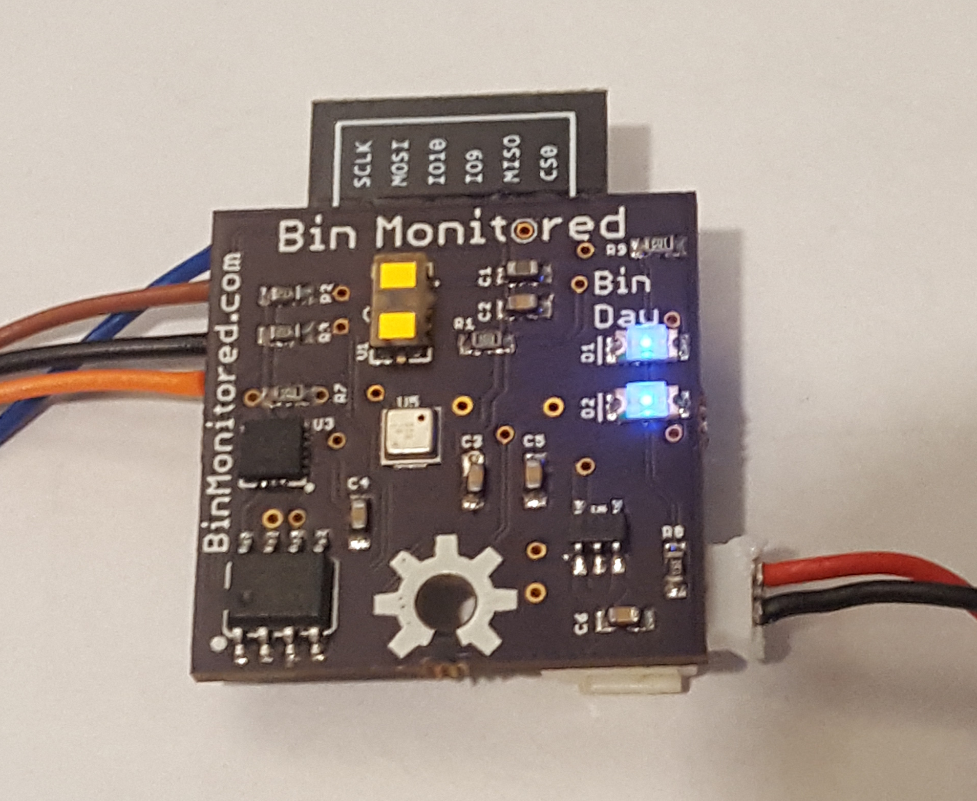
I'd like to say PCB assembly went easily and the PCB worked first time, it almost did, except shortly after I started reflowing the first PCB I noticed I had the distance sensor the wrong way around so I immediately put that PCB to one side. However the second PCB came out a treat and did work first time :-)
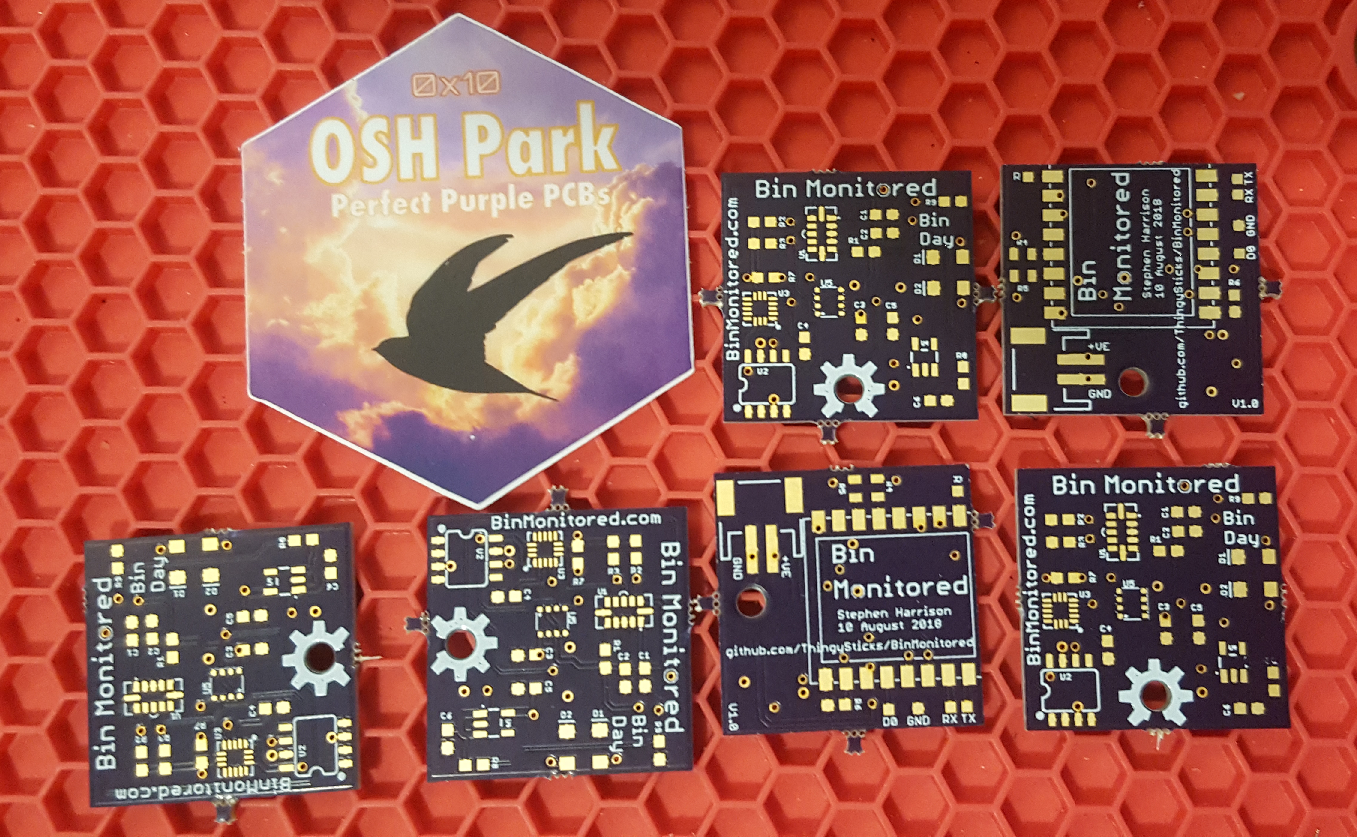
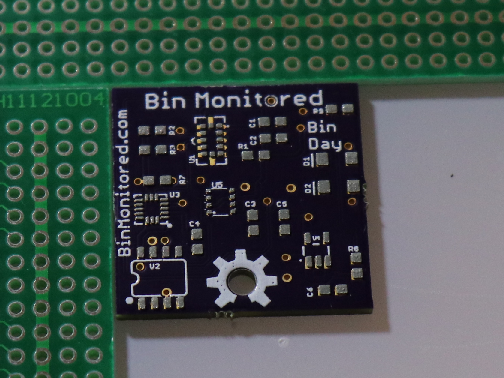
As you can tell from the very purple colouring of the PCBs (and the sticker!) I got the PCBs from OSHPark, I had a stencil made for the top layer at OSHStencils. Each PCB is 25.4mm x 25.4mm (it's almost as if I'd designed them to fit within the Hackaday Square Inch Contest....).
The accelerometer, distance sensor and environment sensor are not at all hand solderable so this was always going to be a job for a stencil and reflow. Theirs only a few easy components on the bottom layer so I hand soldered that.
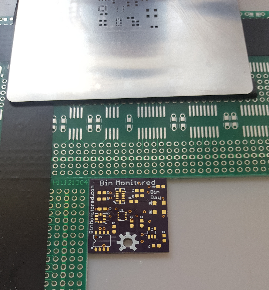
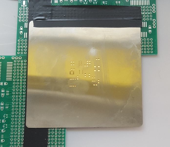
I carefully aligned the PCB with the stencil and applied solder paste.
![]()
![]()
![]()
And used the Steve-Pick-And-Place-Machine to populate the PCB (i.e. me and a pair of tweezers) .
![]()
Then I used my ReflowR to reflow the PCB...
![]()
The nice thing about the ReflowR is you can set it to hot and then remove / rework components if needed. Some time later I did this to the first PCB that I had the distance sensor the wrong way around on. Sadly shortly after that my ReflowR stopped working.
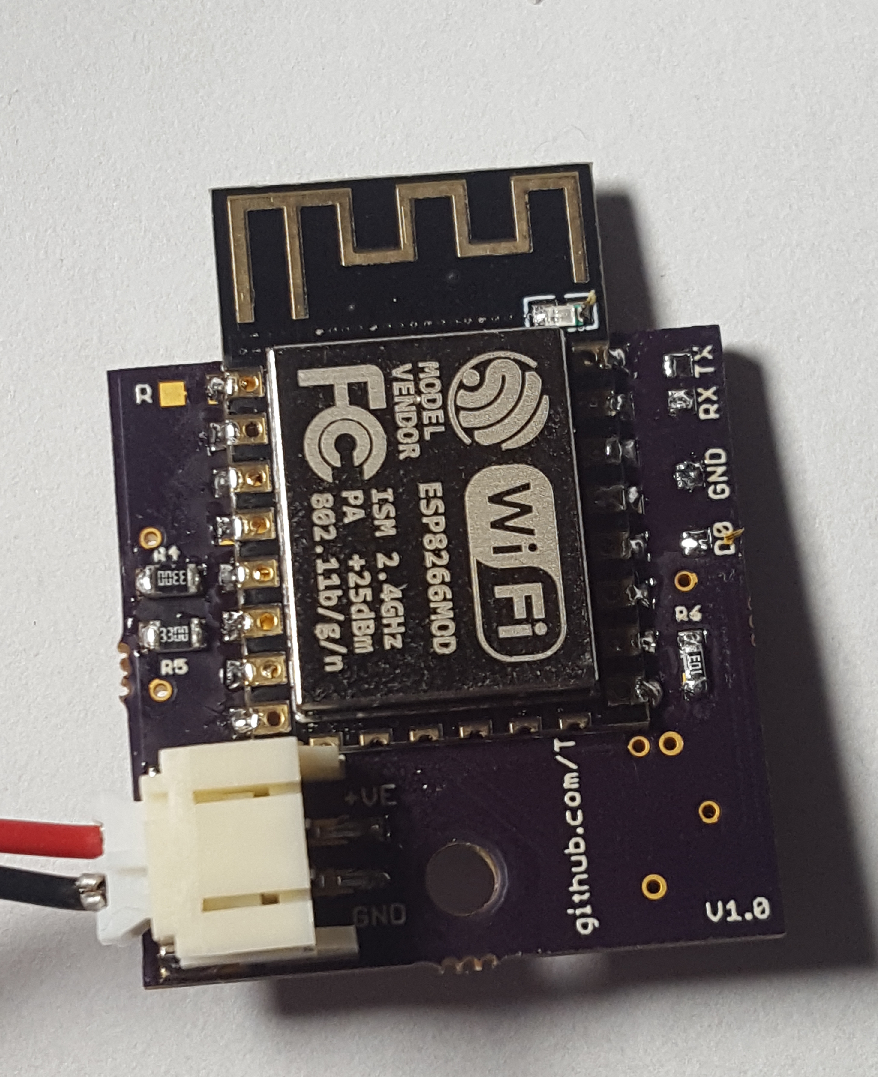
Populating the bottom layer of the PCB is much easier and I did this by hand soldering. The JST socket is probably a little overkill but it was handy during development and testing, however for a final product the battery holder is probably just as well soldered to the PCB. Notice also the solder pads for TX, RX, D0 and GND used to program the ESP 8266.
![]()
-
Perfect Timing
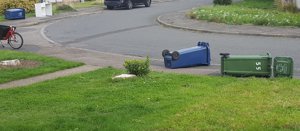
09/18/2018 at 09:15 • 0 commentsI've been after a photo of wheelie bins on their side for this project since I started and didn't really feel like staging it, whilst playing with lower power standby this morning the familiar sound of wheelie bins falling over came through the window...
Indeed, my neighbours bins are on the floor, fortunately freshly emptied so no litter getting blown down the street, had this been the day before it would have been a different story.
Bin Monitored could have saved the day notifying my neighbours their bins had fallen over....
![]()
-
Design Introduction
09/13/2018 at 02:19 • 0 commentsThere are plenty of bin monitor projects around, however none of them really matched my requirements, so I decided to make my own, this log hopefully gives an insight to my thinking.
Schematic:
![]()
Distance sensor:
Most bin monitoring projects I've seen use ultrasonic sensors to sense how full the bin is. I don't really like these because my bin gets washed once a month and those sensors need an opening for the sound waves to travel through which will result in water ingress to the sensor and the whole system.
I decided to use the VL53L1 Time of Flight sensor, that uses an Infra Red laser to sense up-to 4 meters in distance, this can be placed behind something (IR) transparent which would allow the system to be sealed (although at this time I've not tested this, however I plan to use something like acrylic as the enclosure cover so it should be OK and I'm not bothered by accuracy, just an approximate relative change).
The down side is my general rubbish (black) wheelie bin has the rubbish in black bags in it, these may not reflect IR well enough for the sensor. However I'm mainly interested in monitoring my recycling (blue) wheelie bin which contains loose recycling (cardboard, bottles, cans, tubs etc.), and I'm sure I could switch to different bags for the general rubbish.
Lid Lift Sensor:
My blue bin is used for recycling so it's generally clean on the inside, this makes it a good place for delivery people to leave parcels, not all do, but if I'm expecting a parcel and I've gone out I leave a note to get the delivery left in my blue bin rather than disturbing my neighbours, or missing the delivery and this works well for me.
Whilst I'm not too bothered about knowing when the parcel arrives, it would be very easy for the delivery person to leave a parcel in one of my bins and forget to put a note through the door to tell me, this could easily result in my parcel getting put out for rubbish collection by mistake. With the lid lift sensor I can get a notification if the lid has been lifted which hopefully means I've got a parcel waiting for me!
Alternatively it may also mean that my neighbour is using my bin for their rubbish, given we have limited space in our bins this could be very frustrating so this also would prove useful.
I chose a MMA8452Q accelerometer, purely because I've used one before and had a few breakout boards for it, it's got a good range (0-2 to 0-8G) acceleration sensing and a couple of interrupts so it can be used to sense a change in acceleration without the micro controller having to run constantly, which is great for a low power solution. (Side note: I sent the PCB design to OSH Park off before ordering these, and it turns out none of the usual suppliers (Farnell, Mouser, etc.) expected to have them to be in stock before the square inch contest deadline - Epic Fail!, fortunately I managed to pick up some from a seller on AliExpress!
Normally the lid being closed would result in a -1G being registered on the Z axis, when the lid is lifted this acceleration should increase (more +ve) and would then move to the the X or Y axis depending on part orientation, then possibly to +1G on the Z axis as the lid is at 180° and again to the X or Y axis if the lid goes all the way back (i.e. this typically happens when it is being emptied). By sensing the transition from -1G Z to +VE Z and then X or Y acceleration we can tell if the lid has been opened, it should be possible to set the accelerometer to sense the change in acceleration and then register this in the micro-controller.
Bin Down Sensor:
This uses the same accelerometer as the lid lift sensing, again by sensing acceleration in an axis other than the Z axis it can be determined if the bin has fallen over and may be allowing all the contents to get blown down the road in the wind. Notification from the system would allow me to rescue my bin before the street is a mess (I don't always have a direct view of my bin, so the obvious, look out of the window solution isn't always practical).
Environmental Sensing:
I didn't have a special need to add this, however I figured why not, and I actually pushed out the boat and fitted a BME680 which is a fairly expensive sensor as it also includes volatile organic compound gas sensing, allowing air quality to be assessed, along with temperature, humidity and pressure.
My wheelie bins live outside so having an environmental sensor in the bin that is at the same environmental conditions as the outside effectively gives an outdoor (weather) sensor which is shielded from direct sunlight and rain which makes it rather nice, even if not used in relation to the actual bin!
The down side of this is that the enclosure does require air movement to allow for sensing of humidity, VOCs and pressure. With a sealed system the temperature would still be interesting, and the humidity sensors would be able to warn of moisture ingress that could shorten the life of the system.
I decided to have small holes in the enclosure to allow air movement and to place them so any ingress of water during cleaning couldn't directly get to the PCB (and to conformal coat the PCB to further reduce the risk of damage from moisture). The danger of a sealed system is that once moisture gets in it has no way to get out, so this design would allow the system to breath and not trap moisture in it. Rather than large holes as needed for ultrasonic sensors this system can use discrete holes (2-3mm in diameter) away from the PCB.
The VOC side of things is purely experimental, my green bin is used for composting recycling (food and garden waste), I thought it might be interesting to see if this sensor would pick up any decomposition from the waste. Also for the recycling and general waste, any VOCs (paint, spray cans etc.) may give of vapours that could be picked up by this, this could be useful to warn if something has been placed in the bin that shouldn't go for recycing (i.e. paint).
Power:
A solar panel may have been an obvious choice for this monitor, however it would be required to be mounted on the bin lid with wires going trough to the inside, however I wanted the Bin Monitored system to be entirely self contained with minimal damage done to the bin, and maybe even easily removable. It would be very easy for a solar panel to get broken when the bin is emptied or if something falls onto it. Hence I decided to go with just a rechargeable battery and to try and make that last as long as possible.
Indicators:
The PCB includes 2 LEDs on the top. I planned to have 1 LED to indicate if it's bin day. When the lid is lifted the micro controller could light this LED if the bin should be put out for collection. This may require some backend cleverness to make this work, and as the system doesn't include a proper real time clock it may yet not work as intended. The second indicator is intended as a general status indicator, flashing if the lid is open and the battery needs replacing, or no WiFi or some other issue, or just as feedback when debugging.
Micro-Controller:
I decided to use an ESP-12 ESP8266 for this, mainly because it's a small device that's easy to solder and includes wireless communications, it is easy to use and can be programmed with a FTDI cable and the Arduino IDE.
Part of the design was to fit this on a PCB 1 square inch (or less) in size for the Hackaday square inch contest so having a small footprint micro was fairly critical. I've used WiFi for connectivity, however this may not be the most ideal solution and something low power like LoRaWan or Sigfox that doesn't also require a hub would probably be a better solution for this, however for the first version WiFi is good enough and with careful limited usage hopefully wont drain the battery excessively.
EEPROM Storage:
Whilst the ESP-12 includes EEPROM emulated storage on the flash chip this is fairly small and flash can be damaged with lots of writes,. I decided to add an external EEPROM to allow a larger data set to be stored with only occasional transmission (i.e. a full day of 1 minute temperature logs, transmitted once per day to keep the WiFi connection overhead down, but still allowing detailed monitoring).
Backend Service:
Initially I plan to connect this to the Tinamous Internet of Things platform to monitor the system and provide email and sms notifications on interesting events, however I may be slightly biased in my selection of Tinamous (see my profile :) )
Other Uses:
Whilst this is intended as a bin monitor, it could find a variety of other usages. For example:
General environmental sensing:
It's a small self contained internet connected device so could be useful as a general environmental sensor (temperature, humidity, pressure), and as it includes VOC gas sensing could be useful for indoor air quality. The EEPROM could be used to store data through out the day allowing high frequency logging but reducing WiFi activity by sending only when needed (or even if the device is outside of WiFi range with occasional recovery to read the data - i.e. an outside building where WiFi doesn't reach)
Movement sensing:
Using the distance sensor, if somebody walks through or in the beam this could be registered as movement (i.e in a hall way, or stair case, or outside to detect visitors walking up a path), and if placed above the height of pets would reduce false triggers, it could then be tied into a home automation system.
Simple distance measure:
Using the TOF distance sensor this could be connected to a mobile phone and used as a small handheld distance measuring device, or some kind of interactive display that triggers when somebody is close to it.
Bin Monitored
Has your bin been blown over in the wind? Did the delivery person leave a parcel in it? These and more questions answered with Bin Monitored
 Stephen Harrison