Close
0%
0%

An RF Adapter to Make a PS2 Keyboard Wireless

Using FS1000A to communicate between a PS2 keyboard and Host PC

Similar projects worth following
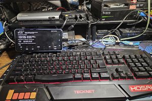
The RF adapter consists of two parts - the receiver and the transmitter modules. The transmitter module uses a CH376S USB host controller to connect to a USB keyboard. However, a suitable alternative would be a PS/2 keyboard with a PS/2 to serial decoder. This module also has an RF FS1000A transmitter. The receiver module has an FS1000A receiver. At the transmitter end, an LPC2148 acts as the interface between the USB host and the RF transmitter. At the receiver end, another LPC2148 acts as an interface between the RF receiver and the PC. The LPC2148 would be connected as a human interface device (HID) .

The project uses two LPC2148's to make a PS/2 keyboard function as a wireless keyboard. The PS/2 keyboard is interfaced to the transmitter LPC2148 using UART. The receiver LPC2148 is configured as a HID keyboard, which then sends this value to the PC via USB. A transmission and reception coding scheme is designed to reduce error probability, which arises due to noise at the transmission and reception terminals.

Receiver.rar

This folder contains all the codes used in the project, at the receiver end.

RAR Archive - 535.38 kB - 11/29/2018 at 11:09

Download

UM10139.pdf

User manual of the development board used at both the transmitter and the receiver side.

Adobe Portable Document Format - 1.56 MB - 11/29/2018 at 04:16

Preview

Receiver_Code.c

This is flashed to the LPC at the receiver end. Link to the LCD code used - http://www.rhydolabz.com/wiki/?p=7164

C Source File - 12.90 kB - 11/29/2018 at 04:14

Download

hut1_12v2.pdf

The Usage Tables give the look-up values for the data to be sent over USB.

Adobe Portable Document Format - 949.63 kB - 11/28/2018 at 22:28

Preview

Block_Diagram.JPG

A block diagram of the system.

JPEG Image - 50.92 kB - 11/28/2018 at 21:57

Preview

View all 6 files

  • 2 × LPC2148 Microprocessors, Microcontrollers, DSPs / ARM, RISC-Based Microcontrollers
  • 1 × CH376S USB host chip, can be used to interface with mass storage devices, USB keyboards, USB mice and other peripherals
  • 1 × FS1000A RF Transmitter and Receiver module Plug-and-play RF module. Interface to the LPCs through UART.
  • 10 × Jumper wires Approximate number
  • 1 × PS/2 keyboard decoder https://www.rhydolabz.com/interfacing-modules-c-80/pc-keyboard-decoder-p-1732.html

View all 7 components

  • LPC2148 as HID Keyboard

    Akul Malhotra11/26/2018 at 10:03 0 comments

    At the receiver end, the LPC2148 must be recognized as a HID keyboard. The data sent by the USB keyboard on the transmitter end would be received by the receiver LPC2148. It can communicate with the host PC as a keyboard only if it is configured as a USB HID device. An easier option would have been to communicate with the Host PC via UART. However, this limits the output to a COM port application such as PuTTy. 

    The support for HID devices is readily available on the ARM website. The standard example implements a general purpose input/output HID device. According to the USB protocol, changing the descriptors should actually be enough to make the LPC to behave as any other peripheral compatible with USB. The documentation on the ARM website mentions that the only descriptor needs to be changed is the report descriptor. However, this failed to work. The error that showed up when it was connected to the host PC was 'Device Descriptor Request Failed'. Changing other descriptors had no effect and the errors persisted. A few other errors that popped up during enumeration was 'Invalid Configuration Descriptor'. The device was also tested on Ubuntu, again to no avail. 

    USBView is a Windows debugger which gives the details of all the components connected to the USB ports of the host PC. It also shows the exact configuration, device, endpoint, interface and HID class descriptors of connected devices. By connecting the USB keyboard directly to the host PC, these values were noted down. The receiver LPC was then configured using these values, but the host PC still failed to recognize it as a valid USB device. The descriptors of other devices were also tried, including a USB mouse. Surprisingly, the LPC was detected as HID-compliant mouse for a short while. After that, enumeration failed as usual. 

    Turns out that the value of the descriptors determines which systems the device could be detected on. With some help, we were able to configure the LPC as a HID keyboard. However, this only worked on Lenovo machines running on Windows 10. 

    Another change that was required in the default code was the IN report. This has an 8 byte format. The first byte is the modifier, which indicates the status of the shift, control and alt keys. he next byte is reserved. The other bytes represent the keycodes. In this project, we only use the first one. 

View project log

  • 1
    Flash transmitter LPC2148 with the transmitter code

    The transmitter code has been provided in the files section. 

    Connect pin 0.9 (UART 1 - RX) to the data pin. Also make the appropriate Vdd and ground connections. The received signal is then repeatedly transmitted through 0.0 (UART0 - RX) to the data pin of FS1000A Transmitter. This is done so that the receiver does not pick up noise in between successive transmissions.   The schematic of the transmitter side and our circuit can be seen as follows:

  • 2
    Flash receiver LPC2148 with the receiver code

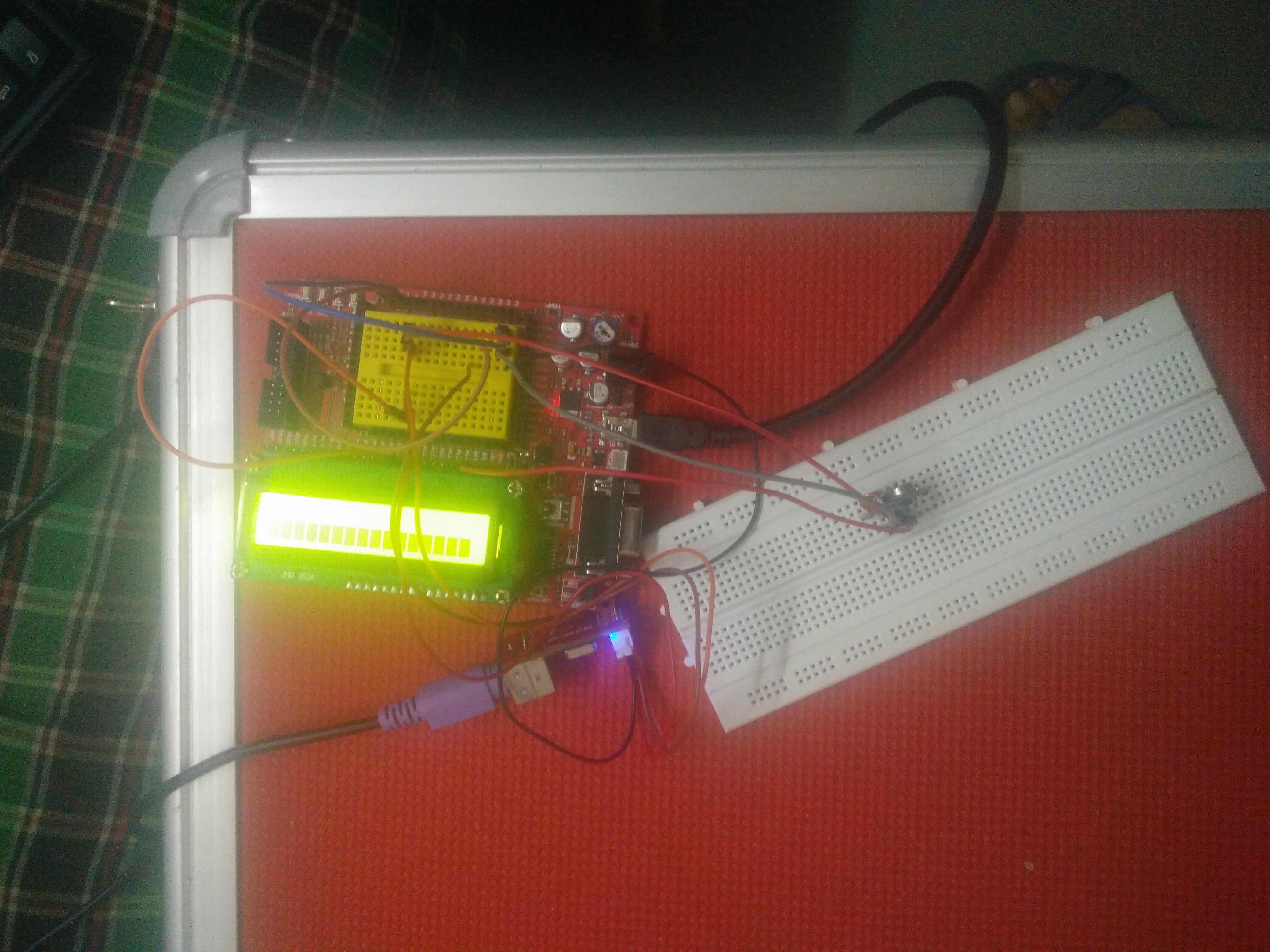
    At the receiver end, we have 0.9 (UART1 -RX) connected to the data pin of FS1000A Receiver. This is then decoded (code is attached in one of the previous sections) using a look-up table. Support for more keys can be added. The LCD is also initialized to assist in debugging.  The schematic and the circuit can be seen below:

  • 3
    Receive output on a text editor

    The receiver LPC is flashed with the receiver code, with the ISP jumper in place. After flashing, the ISP jumper is removed, and placed to connect the JTAG pins. Any value pressed in the PS/2 keyboard should ideally appear on the LCD screen. If it does not, then wait for some time for the receiver to perform gain adjustment. Now the received values must automatically write into any open text editor window. 

View all 3 instructions

Enjoy this project?

Share

Discussions

Similar Projects

Does this project spark your interest?

Become a member to follow this project and never miss any updates