Dan Julio
-
Bugs and Corner Cases
12/28/2018 at 06:55 • 0 commentsMy choice of an inexpensive micro-controller has a cost. This product has firmware that will probably never be upgraded since there is no facility to easily load new code (no interface and not much space left over for a bootloader). So the release firmware needs to be pretty close to perfect. It helps that this isn't a very complex device and I tried to make architectural decisions to mitigate entire classes of problems. Still, with about 4300 lines of C, there are bound to be bugs. And there have been. Initially, of course, I found lots of simple bugs that were also pretty easy to find and fix. After the system was pretty functional I executed a test plan to verify all major functionality under the main operating conditions. This found a few more issues, things like incorrect status bits in a register. Then I started testing as much as possible in real-world conditions - which for this system meant devices running for extended periods on solar power in as many different conditions as possible.
That's when things got interesting. Throwing wildly varying solar conditions, battery voltages and conditions, temperatures and loads into the mix started uncovering the corner cases. Slowly. The best tool I have had is the ability to log all the main parameters via the daemon running on a Pi because some of the corner cases didn't crash or harm anything, they just made the system less efficient.
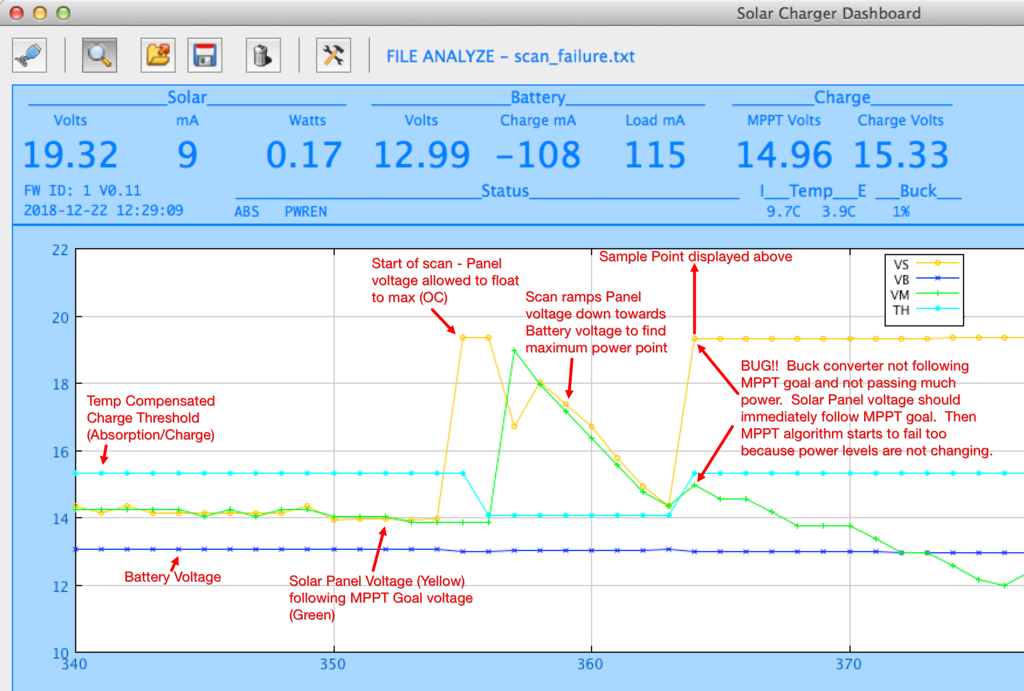
Recent winter testing just uncovered one of these corner cases. It was exposed because the desired MPPT voltage was less than the desired charge voltage for the battery. I found it looking through data from a cold overcast day.
![]()
The firmware periodically executes a scan to find the current maximum power-point because there is a slight risk of the P&O MPPT algorithm wandering off from the ideal maximum power-point (less risk in a design like this with one small solar panel than with a large-scale system with larger or multiple panels where shading can cause local power minima and maxima). After one of these scans I saw that the buck regulator was not operating correctly, in fact barely operating at all, and was not tracking the MPPT which then caused the MPPT algorithm to fail because there was no change in power as it adjusted the MPPT voltage goal. In absolute terms, this bug was not severe because it occurred at a point where the system was producing relatively small power and was corrected by the next scan ten minutes later. I hadn't seen it before (although it may have happened) because it would only manifest when the light was low leading to a low MPPT power-point for the panel and the battery charge threshold was high because the charger was in the Bulk/Absorption phase and the low temperatures caused the compensated charge voltage to be high (15.33 volts in this case). The actual bug occurred because at the end of the scan the charger attempts to initialize the buck converter PWM value based on a simple CCM calculation representing the fraction of the output voltage to input voltage:
pwm = MAX_PWM_VAL * OutputVoltage / InputVoltagewhere the MAX_PWM_VAL is 1023, the OutputVoltage is the desired charge voltage and the InputVoltage is the MPPT goal. The buck control logic will then, over time, adjust the PWM value to the actual ideal value but this is a good starting point for most cases. My problem was that the InputVoltage was less than the OutputVoltage and I didn't check for that. The 16-bit variable holding the 10-bit PWM value overflowed 10-bits. The actual PWM peripheral only looked at the 10-bits so was set to a small value. However the code worked on the 16-bits and the buck logic wouldn't allow a change because it was already over the maximum PWM value. The fix is easy. In this case the PWM should be set to the maximum value essentially directly connecting the panel to the battery for these low-light, low-power conditions. It's the most efficient too as there are no switching losses. I had never assumed that the MPPT voltage would be less than the charge voltage.
There have been a few other interesting corner cases which is why I want to test through the winter season before releasing the firmware in the product.
Early on, the scanning process showed another, potentially harmful, anomaly during the summer season with plenty of high intensity light. Lead Acid batteries have an interesting characteristic where, when they are nearly charged, dumping a lot of current into them causes their voltage to shoot up. Normally the buck converter control algorithm limits the power transfer for several reasons, first to hold the solar panel voltage to the MPPT goal, second to hold the battery voltage to at or below the charge threshold and finally to limit the maximum current flowing through the buck circuitry. However the limits on voltage need to be disabled during scanning to ensure we are seeing the true maximum power-point. This caused the battery voltage to shoot up way past the charge threshold when it was nearly charged but the system was still in the high-threshold Bulk or Absorption charge states and the panel could produce a lot of power. The temporary high voltage probably wouldn't harm the battery (I don't know about repeated cases) but I thought there was a risk that it would exceed the 18V maximum input of the 5V buck converter or a customer load applied directly to the battery output. The fix for this was simple too. The system suppresses the scan activity whenever the buck converter is limiting since the fact it is limiting means that the system doesn't have to operate at the maximum power-point. There's no need to find that until solar power has fallen off to the point where the system isn't limiting the power transfer.
Another interesting corner case occurred when the system would shut down the load for a depleted battery. When the battery voltage falls below a configurable minimum (default 11.5V) the system alerts the load with a one minute warning and then powers off the 5V output until the battery is charged to another configurable set-point (default 12.5V). However I saw that an old battery will bounce back once the load is removed temporarily exceeding the restart set-point, which restarted the load immediately. The system then went through several cycles of power-down/power-up until the battery was sufficiently depleted so the bounce didn't restart the system. The fix for this wasn't immediately obvious but I settled on having the system see the battery charge for at least an hour before restarting if the battery voltage was above the restart set-point.
Currently I am trying to track down a potential issue that, in almost a year of testing, I've seen only twice. The daemon program that runs on the Raspberry Pi can automatically shut the Pi down in a controlled fashion if it sees an impending low-battery shutdown alert from the charger. It senses this by reading the STATUS register once per second. The power management code is designed to switch off 5V power one minute after signaling the alert in order to give a system time to do a controlled shut down. However in both cases the daemon initiated a shut down but the charger did not kill power. In fact log data shows a charged battery voltage so I don't understand how the alert is being generated. I've done testing reading the STATUS register repeatedly without ever seeing a read failure and tested the code path related to alerts and shut downs without any failures. I did add code to require a continuous low-battery condition for 1 minute to prevent a momentary droop in battery voltage from triggering a premature shutdown but I saw the failure again last week after this code was added. So now I've instrumented the daemon to dump a bunch of register values if it sees the alert before shutting down. We'll see...
-
Winter testing
12/22/2018 at 18:49 • 0 commentsI finally overcame inertia, took advantage of some reasonably nice weather and built up two frames so I could do some testing during the winter season. Testing in summer, at least here in Colorado, is easy. Weather is fine and there is an abundance of sunlight. One just has to make sure the solar panel won't blow away in a high wind. Its orientation is less critical. Winter, especially where I live in a valley at the base of the Rocky Mountains, is more challenging. There are only a few hours of sunlight a day and temperatures are often freezing or below. It's definitely a good test environment for a charger that is to keep a device running 24/7.
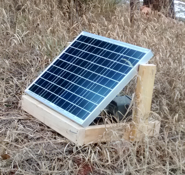
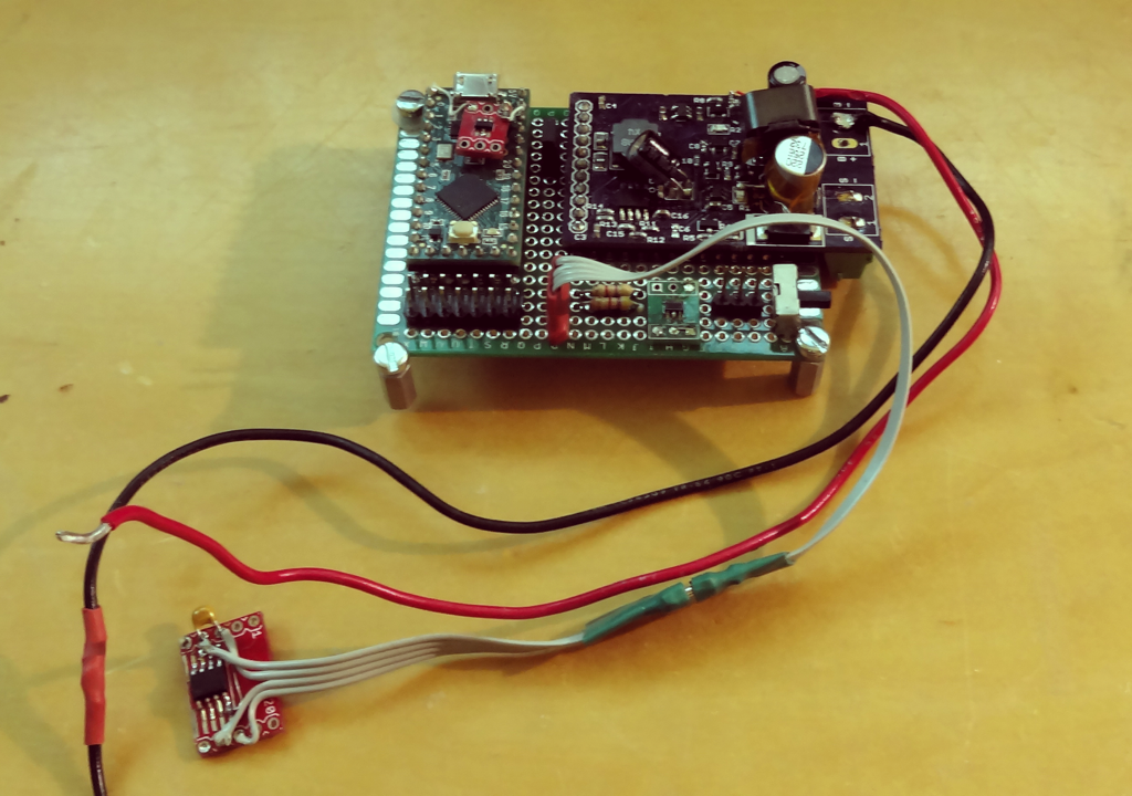
I loaded the current firmware on my original outdoor prototype and built a simple wooden frame to hold the panel. This device has an old 40W panel, Rev 1 charger, an old-ish 9Ah battery and a Raspberry Pi Zero with camera module and USB WiFi dongle as the load. It's located near the house so it can talk to the local WiFi. It is logging using the mpptChgD daemon and I can monitor it in real-time using mppt_dashboard. Once in a while I log into the motion-based webcam server to see the side of my house and down-valley. Not a particularly exciting image but it does consume an extra 10-15 mA...
![]()
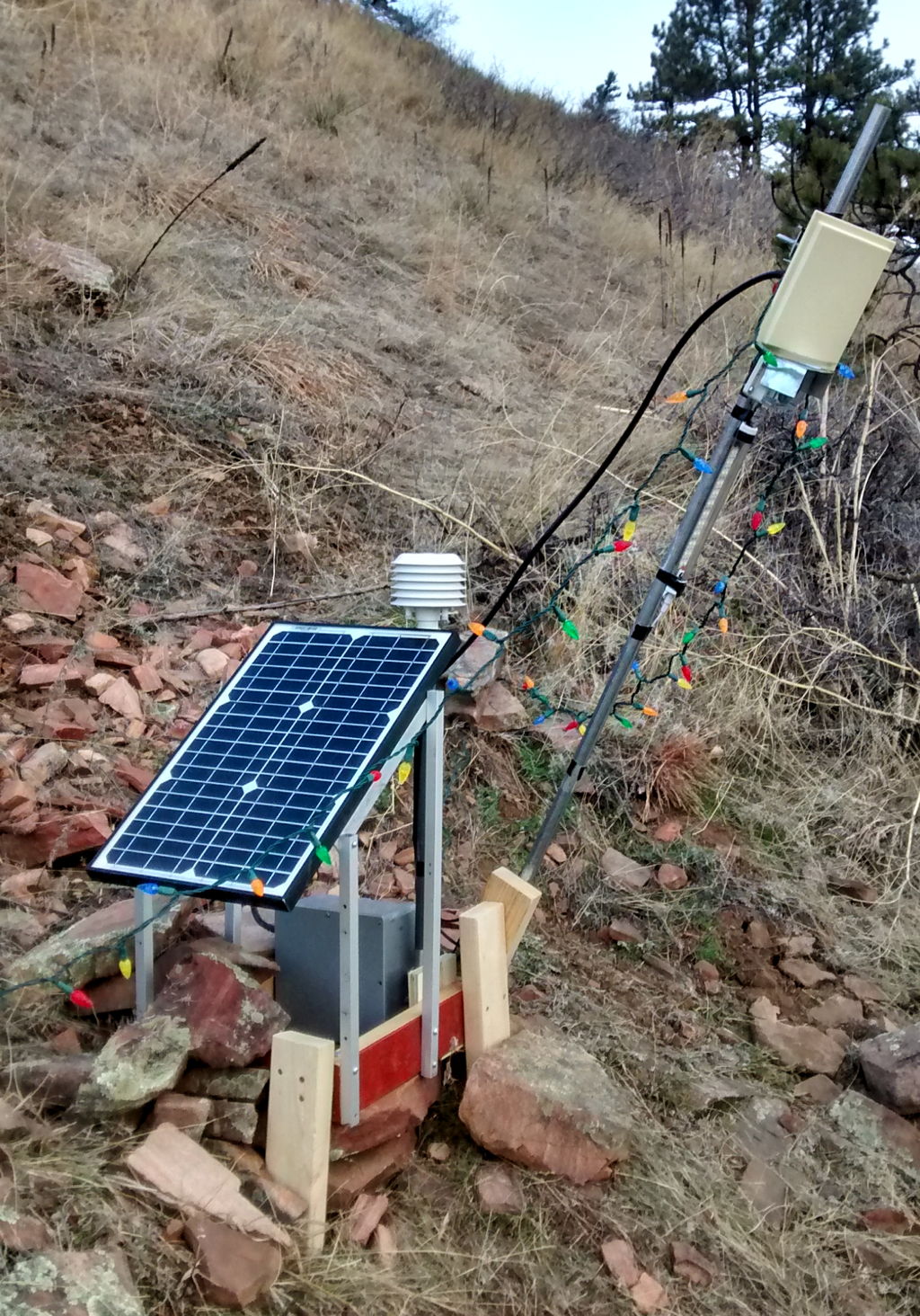
The other test platform is a little more ambitious. It's based on a pair of openwrt-based 8devices Carambola 2 modules with directional antennas in order to operate at a larger distance powered by a 25W panel, a newer, but still used, 9 Ah battery and a Rev 2 charger PCB. It's the kind of device I envisioned when I started designing the charger. It sits a ways up the hill above the house and sports a camera, an external temperature sensor and a couple of Auxiliary power channels - one controlling a bright white LED light for the camera and the other a string of 12V Christmas lights for a more useful load test. Hopefully the rocks you see piled on the base will keep it stable in the sometimes 60 MPH winds we have. It uses a DF Robot Beetle arduino Leonardo clone to communicate with the charger (and control the loads). The Beetle uses I2C to talk to the charger and a TTL serial port to communicate with the Carambola 2. I'm running ser2net on Carambola to remotely access the system. I want to write a simple data recording program running on a local server to log data from the charger. The Carambola and Beetle present about a 90 mA continuous load to the battery (less than 200 mA @ 5V). The Christmas lights are pretty frugal, only adding another 110-120 mA when switched on. The bright white LEDs are more power hungry at 420 mA. I'm planning to run the Christmas lights for a few hours ever night during the holiday.
![]()
I expect that there will be many days where the panels don't produce. It will be interesting to see how the systems hold-up.
Edit
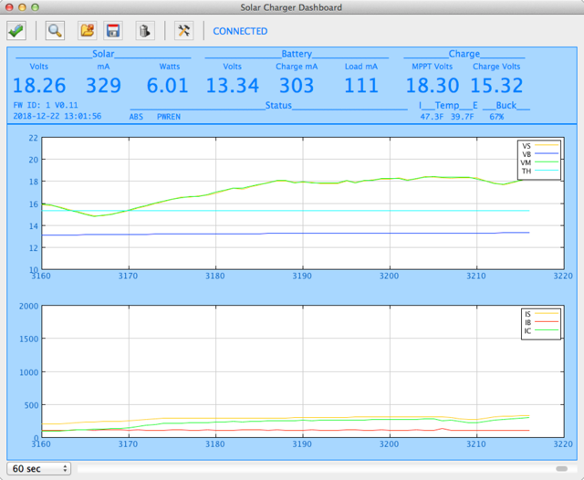
Here's a typical output from the first system on an overcast day showing a few watts from the panel. The charger state machine is in Absorption Charge (it hit the Bulk limit earlier in the day when there was full sun for a while) but it doesn't have enough energy to hold the battery at the desired Absorption charge level (temperature compensated at 15.32 volts) so the system is effectively operating as a float charger at this time. You can the MPPT algorithm at work too. The Vmpp from the panel is lower with lower light and in this 60 second interval the light increased some and the Vmpp rose to follow (green VM in the top graph - yellow VS is the system holding the solar panel output to match).
![]()
-
Onward toward manufacturing
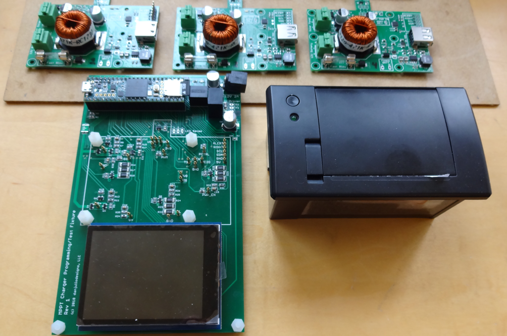
12/06/2018 at 03:28 • 0 commentsGot the manufacturing test fixture designed, boards back and built. Now to write code. The test fixture will program code into the on-board micro (actually program two programs, the first used to find the micro's calibration value) and perform a functional verification of the electronics via pogo-pin connections with test points on the bottom of the PCB. I am using a PJRC Teensy 3.5 as the test fixture controller. The technician will interact with the controller to initiate programming and testing via a capacitive touch LCD screen (one thing I learned from Sparkfun's production line as a collaborator was that mechanical switches quickly wear out). For boards that fail the programming and test procedure a small thermal printer will print out a diagnostic output to go along with the failing board for later repair. I hope to be able to have the print out identify portions of the circuit to focus on.
![]()
You can see some power resistors that act as a load when switched onto various subsystem outputs by a N-Channel MOSFET. If you look closely you can also see that I forgot to send them milling gerber layer to the PCB vendor for the non-round power connector contacts...
The test fixture, a power supply and printer will go on a base. I'm not sure if I'll ask that the board be secured using screws or if I'll try to build something to press the board down onto the pogo pins. In addition I also want to figure out an optical sensor to verify the on-board LED. I bought some photo transistors that have sensitivity in the green range. Just have to figure out how to have them see only the light from the LED and not ambient light.
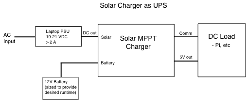
Not just for Solar Power!Have an old laptop power supply? It can turn the charger into a long-lived UPS for small computers like Raspberry Pi file servers or a 5V router or WiFi access point. I hooked an old Dell 19V 3.5A laptop supply to the solar input and the system worked flawlessly as a UPS.
![]()
The charger will initiate charging once the solar panel voltage exceeds 18VDC. Many laptop supplies put out between 19 - 21 volts. This is perfect as a source of power to both keep a battery charged and power a load through the 5VDC output (or even the direct battery connections although there won't be automatic low-battery shut down without extra circuitry). The MPPT algorithm will find the power supply's set point and the charger will keep the battery charged without damaging with it's FLOAT charge state. The battery will take over the load if the AC power fails and the existing auto-shutoff software support can ensure a controlled system shutdown if necessary if the battery is ever exhausted. Depending on the load, this UPS can keep a load running for many hours or even days without AC power. Even with a 10 watt 5V load (taking about 1 A from the battery/PSU) there will be at least an amp available for recharging the battery when power is restored. The system will get warm under heavy load so some kind of cooling might be necessary, especially if it's in an enclosure. Easiest would be to connect a 5VDC fan to the board so that it's also shut down for low battery cut-off.
-
Characterizing the Buck Converter
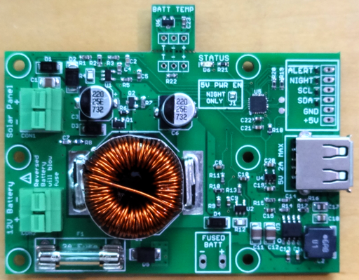
11/03/2018 at 20:40 • 0 commentsFirst up, the latest revision. Small changes from the last version including tightening up various current loops in the buck converter and moving the battery-side transient TVS diode to the anode side of the reverse-polarity protection diode to reduce the transient generated when the battery is reverse connected before the fuse blows. Looks like a good candidate for production but some more testing to finish. New schematic in the repository.
![]()
One measurement available through the I2C interface is an estimated battery charge current (IC). It is also used as part of a calculation to determine when the Absorption charge phase is finished and the charger should move to Float charge (battery charge current falls off). It is estimated instead of measured because unlike all other paths in the charger where current flows one way, current can flow into or out of the battery and it would take a more complex (and expensive) circuit to measure a bi-directional current than the TI INA180 current amplifiers I am using.
The calculation is straightforward but requires an estimate of the buck converter efficiency.
EstimateBuckOutputCurrent = MeasuredSolarInputCurrent * (BUCK_INPUT_V / BUCK_OUTPUT_V) * BuckEfficiency

BatteryChargeCurrent = EstimateBuckOutputCurrent - MeasuredLoadCurrent
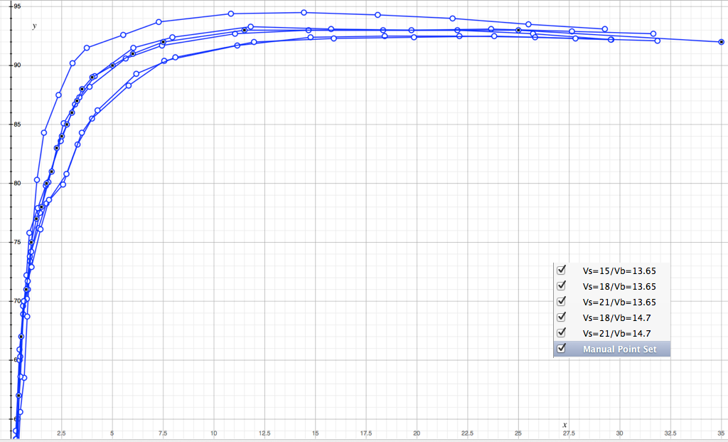
I had done some measurements with an early prototype and found an efficiency of about 90% at a mid-range current so I hardcoded this into the calculation. However the buck efficiency is dependent on the power level and falls off very quickly for low power levels making the calculation inaccurate. I finally got around to characterizing it more fully which resulted in the addition of a fast piece-wise lookup table in the code translating solar power (VS * IS) into an efficiency value for the calculation. I hacked the firmware so the buck converter regulated on the output voltage (VB) instead of attempting to hold the input voltage (VS). Then made a series of measurements (efficiency vs. input power) for five sets of conditions (varying VS between 15V, 18V and 21V and VB between 13.65 for float and 14.7 for bulk/absorption). As expected the converter is most efficient when the difference between input and output voltage is the smallest and reaches 90% efficiency at about 5 watts. Peak efficiency reaches 93-94% at between 10-20 watts. Not bad for an asynchronous converter.
![]()
To make the efficiency table, I played around unsuccessfully for a bit with curve fitting before giving up and just hand-picking points that represented reasonable piece-wise values in a graph of all the measurements. I centered the values around the VS=18V curve since that was the middle measurement and hopefully where an MPPT charger will spend time. The highlighted graph are my hand-picked values. The X-axis is solar power (W) and Y-axis converter efficiency (%).
![]()
The code is then pretty easy and efficient on an 8-bit micro.
//-----------------------------------------------------------------------------
// Efficiency lookup table - efficiency (percent) as a function of input power (mW)
//   determined via hardware measurement
//-----------------------------------------------------------------------------

#define BUCK_NUM_EFF_ENTRIES 22
code const uint16_t buckEffPowerPoints[BUCK_NUM_EFF_ENTRIES] = {
    250, 375, 500, 750, 1000, 1250, 1500, 1750, 2000, 2250, 2500, 2750, 3000, 3250, 3500, 4000, 5000, 6000, 7500, 11500, 25000, 35000
};

code const uint8_t buffEffValues[BUCK_NUM_EFF_ENTRIES] = {
    56,  62,  67,  71,  75,   77,   78,   80,   81,   83,   84,   85,   86,   87,   88,   89,   90,   91,   92,   93,    93,    92
};


uint8_t BUCK_GetEfficiency(uint16_t ps)
{
    uint8_t i = 0;

    // Find the efficiency value for the first power point immediately
    // above the current solar power input
    while (i < (BUCK_NUM_EFF_ENTRIES-1)) {
        if (ps < buckEffPowerPoints[i]) {
            break;
        }
        i++;
    }

    return(buffEffValues[i]);
}
Another recent change is to change the buck converter PWM from 8-bit to 10-bit. This slightly slows its response time (since it takes longer to make big changes) but significantly reduces the MPPT P&O algorithm jitter because a single count change in buck PWM has a smaller effect on the solar input voltage. I have an arduino with LCD as a text fixture displaying all the measurements as fast as it can and the jitter in VS, IS and IC are all much smaller.
-
Improving measurements with jitter
10/19/2018 at 03:14 • 0 commentsA deep dive into the ADC measurements led to two firmware changes that have dramatically improved the system's accuracy.
- Storing the actual on-board reference voltage.
- Slightly jittering the ADC sample points over time.
The Silicon Labs EFM8SB1 micro-controller's built-in 1.65 volt reference has a fairly large specified operating range of 1.62 to 1.68 volts. I tested several parts and found that the reference did, in fact, vary from part to part. Without a known reference it would be impossible to get accurate measurements. I decided to add the ability to calibrate each board during manufacturing instead of adding a more precise external reference for cost reasons. Various internal calculations were already using a constant 1650 (mV) to compute voltage and current readings so it was easy enough to store the constant at the top of code space so that the programming fixture can load a custom value for each unit it programs (by changing, on-the-fly, the hex code that's programmed into the device). This means two different programs loaded, one to calibrate and then the real firmware with the calibrated reference voltage substituted for the default value of 1650. It took a slight bit of gymnastics to make the C-compiler place a constant at a specified location in code-space and there is a warning about a memory space overlap I can't seem to get rid of. The trick was to define a variable in code-space at a specific location for use by the calculations:
//-----------------------------------------------------------------------------
// Internal Reference Calibration value - stored at the top of code memory
// so a calibrated value can be loaded into the processor by a production
// programmer.
//-----------------------------------------------------------------------------
SI_SEG_CODE int16_t adcVRefMv _at_ 0x1FFD

...

// Compute a voltage reading in mV from the ADC raw count
//  mV = (ADC_COUNT * VREF * V_SF) / 4092
//
uint16_t _adc2mV(uint16_t adcVal)
{
    uint32_t t = (uint32_t) adcVal * adcVRefMv * V_SF;
    t = t / 4092;  // Max summed 12-bit ADC value is 4092

    return (t);
}
and then initialize code-space using an assembly language module in a different file.
CSEG AT 01FFDh
ADC_REF_VAL_HIGH: DB 06h
ADC_REF_VAL_LOW:  DB 6Fh
END
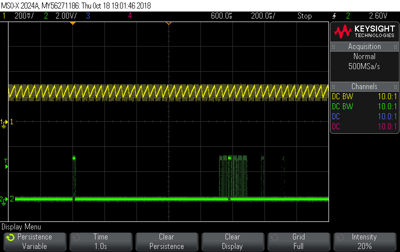
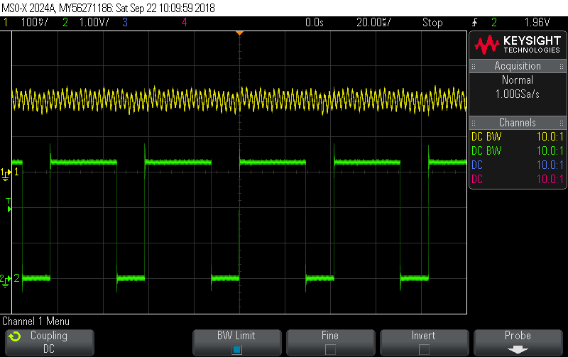
This change improved the accuracy of all measurements except the solar current (input into the MPPT Buck converter). This is because the delta current is large as the buck switching transistor is turned on and off (at 24 kHz). In addition both the PWM module generating the buck control signal and the timer generating the 4 kHz interrupt for the ADC sampling module are based on the same system clock. Each of the main analog signals (Vs, Is, Vb, and Ib) are sampled every four interrupts (minus occasional samples of the temperature sensors). The solar current, Is, was sampled about every 1 mSec and at the same place on the analog signal coming out of the current monitor as shown in the following scope trace. This lead to an error depending where on the analog waveform it sampled. The yellow trace is the output of the current sensor being sampled. The green trace is a diagnostic output set when the ADC is triggered for the Is reading and cleared when the ADC finishes the measurement (IRQ).
![]()
Since the ADC values were being filtered through a fairly slow software filter (140 sample rise time), an immediate solution seemed to be to jitter the ADC sample point slightly so that over time it would sample all positions of the input signal. This turned out to be fairly simple since the ADC was triggered by a timer IRQ. The timer IRQ just adjusts the next period by one time count up and then down within a range that covers the buck PWM period.
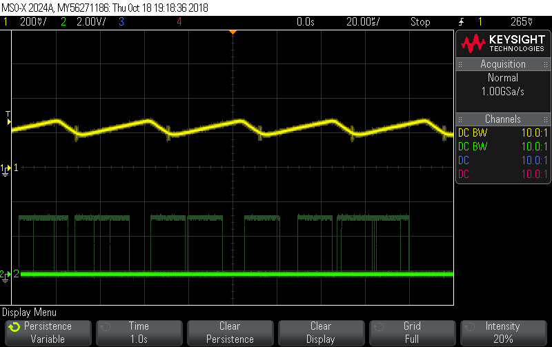
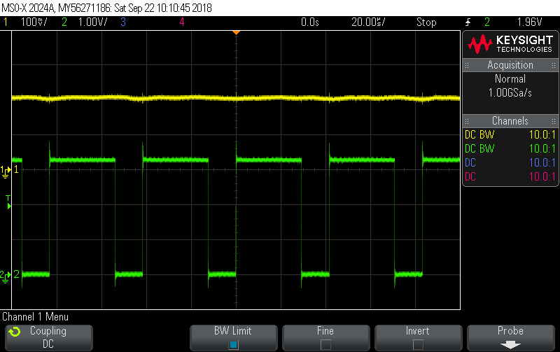
    // Update the reload value to skew the period between samples
    if (adcTimer0ReloadInc == 1) {
	if (++adcTimer0Reload == _ADC_TH0_MAX) {
	    adcTimer0ReloadInc = 0;
	}
    } else {
	if (--adcTimer0Reload == _ADC_TH0_MIN) {
	    adcTimer0ReloadInc = 1;
        }
    }
    TH0 = adcTimer0Reload;
Setting the scope to trigger on the ADC trigger and enabling persistence shows how the measurement jitters over time.
![]()
Or setting the trigger to the PWM signal and using several single captures summed using persistence.
![]()
Note that I am using a special ADC mode on the micro to create a 12-bit reading using four 10-bit conversions, each with a different reference voltage and combines them into a single result with a maximum value of 4092.
The result was a marked improvement in the accuracy of the Is reading with various measurement devices (DMM, external PSU and firmware) agreeing to within a few mA.
-
(In)Accurate Measurements
09/24/2018 at 20:39 • 0 commentsPutting control of a device like this into firmware requires accurate measurements of the data required by the algorithms and probably the area I spent the majority of time while testing with prototypes was getting reasonably accurate voltage and current measurements from the micro's ADCs. This is because values fluctuate greatly as the buck converter (or PWM) switches on and off, especially the current values. Incorrectly sampling these lead to wildly incorrect measurements. In fact, this was a question I had about some of the other charger solutions I saw. There didn't seem to be much, if any, signal conditioning or filtering.
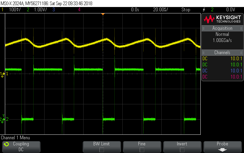
I use a simple voltage divider (1/15) to measure solar and battery voltage and a TI INA180 high-side current sense amplifier (generates a voltage equal to 20 x drop across the 0.025 ohm sense resistor). The MPPT buck converter runs at about 24 kHz while the 5V output buck converter runs at about 500 kHz. A typical output of the Solar current sense amplifier (along with the MPPT buck converter PWM signal in green) is shown below.
![]()
The signal has a huge variation as the main inductor charges. A very fast sample rate (multiples of the PWM frequency) could be used to process the signal completely in code but that is way beyond the capability of most inexpensive micro-controllers. Low pass filtering will work too but INA180 amplifier stability sensitivity makes it more difficult to build an inexpensive low-pass filter for the relatively slow solar buck (trade-off of required impedance for the ADC and load on the INA180). The current prototype uses a combination of a simple RC low pass filter with a roll-off at around 16 kHz and a low-compute requirement software filter driven by a 1 kHz sample rate. The output of the RC low pass filter provides the ADC with the following signal for the solar current (the most variable of all signals).
![]()
The software filter implements a low frequency bandwidth for the current of about 3 Hz and 20 Hz for the voltage signals.
The higher frequency battery current signal is mostly cleaned up by the RC filter.
![]()
![]()
The original PWM charger prototype had an interesting issue measuring the solar voltage. When the transistor is switched on the panel voltage is dragged down to the battery voltage (minus the voltage drop across the transistor). When the transistor is switched off it floats back toward the open-circuit voltage. The firmware needed the open-circuit voltage to make decisions so periodically it turned the PWM off for a measurement interval and took a reading at the end of the interval when the panel voltage had recovered (the PWM frequency was about 500 Hz). The prototype didn't measure the solar voltage with the transistor switched on which would have been necessary to compute power. It did, however measure the current and battery voltage values after the PWM period started and the transistor was switched on. This was not ideal either because the current and voltage levels changed during that time. Unfortunately I did not take any scope images to illustrate. To get more accurate readings would have required a burst of reads during the on-time of the PWM period and an average computed for those. The higher frequency of the MPPT buck converter actually makes the problem easier. I'm guessing that commercial PWM chargers like those made by Morningstar (e.g. SunKeeper series) only try to regulate the battery voltage (easier to measure) and measure solar panel voltage occasionally only to know when the sun is shining or not.
Determining what the actual value is from test equipment is interesting. For example, as I write this I have the system running using a lab power supply for solar power with a charged battery and controlled load on the battery. This minimizes variability as the firmware hunts for optimum regulation. Battery is at a float charge level of 13.5 volts, power supply set to 18V output and load at 400 mA.
- Power supply reports solar current of 345 mA.
- DMM set to measure current in series with solar reports current of 346 mA.
- Scope measuring output of filter reports (after converting voltage back to current) reports current of 332 mA using Average and DC RMS measurement functions over many samples.
- DMM Set to measure voltage measuring output of filter (after converting voltage back to current) reports current of 340 mA.
- My firmware reports current of 352 mA.
The spread increases at higher currents. At 900 mA load, input current ranges from 740 mA on the scope to around 750 mA with the meters to 770 mA from my firmware.
Clearly there are some issues with my measurement of solar current. I do see a slight positive bias on other readings so its possible there is either something about the ADC I don't understand or a reference issue. It's also possible there is an aliasing issue when measuring the solar current since the MPPT buck PWM reference is derived from the same system clock as the trigger for the ADC measurements (output of a timer). Stuff to figure out.
-
PWM or MPPT: That is the question
09/20/2018 at 18:06 • 0 commentsTwelve-volt solar charging systems have a long history. Before charge controllers panels were connected directly to the battery through a blocking diode to prevent battery discharge by the panel at night. The panels were sized so that they could still put out enough voltage to charge the battery when dragged down to its potential. What we call "12V" solar panels are actually made up of 36 series cells which can put out an open-circuit voltage of 21-23 volts. There was no charge cycle and the panels had to be sized to the battery capacity so that a too-large panel wouldn't overcharge the battery. Often, and still today, smaller solar panels were used to provide float charges to keep unused batteries topped off.
Eventually relays and voltage comparators were added to chargers to prevent overcharging. As large scale solar power became feasible, more sophisticated charge controllers were developed along with better charge algorithms. The main types are PWM-based and MPPT controllers. They allow controlling the battery charge voltage enabling the Bulk, Absorption, Float charge algorithm that initially charges the battery to a higher voltage and then keeps it charged at the lower float voltage. MPPT controllers provide the additional capability of optimizing power output from the solar panel by controlling its output voltage. PWM controllers use a switching element like a P-Channel MOSFET to control the duty cycle the panel is connected to the battery to control its voltage. MPPT chargers use a controllable buck converter to also control the solar panel voltage to keep it at the maximum power output level (by measuring its output current and voltage). I wasn't able to find a history of PWM chargers but the first MPPT charge controller was apparently designed by an Australian named Stuart Watkinson.
My original idea for this charger was to implement a PWM version for two reasons. First, it is less expensive than a MPPT circuit and every penny counts for a tiny-scale American producer like myself. Second, for 12V systems there isn't a lot to be gained by using MPPT (the batteries and panels are fairly well matched). MPPT systems are much more idea for matching much higher-voltage panels to batteries.
![]()
However as I played with an initial prototype that used a Teensy-LC as the controller, I became enticed by the idea that by adding an inductor, a diode and an output capacitor (plus more firmware), I could have a MPPT charger controller. The original PCB prototype had the PWM bypass P-channel MOSFET and driver, the ability to measure solar panel and battery voltage and current, a 3.3v supply for the Teensy and a 5V output converter. You can see an inductor, diode and some capacitors wedged onto it here. The 8-pin SOIC hanging off of it is an I2C-based temperature sensor (temperature compensation).
![]() The PWM charger really only needs to know the battery voltage although other measurements are useful . The MPPT charger also requires the solar panel voltage and current to compute the output power it optimizes. Battery current is not necessary but is of interest to determine efficiencies.
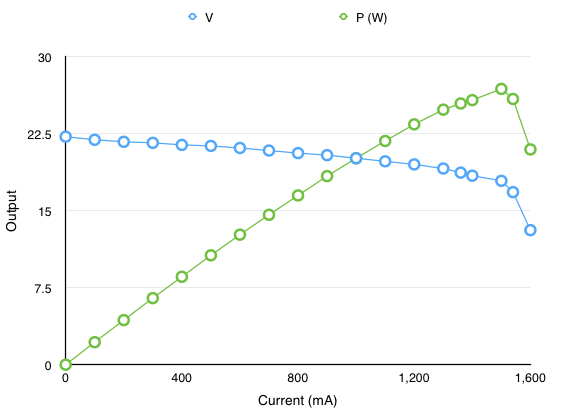
The PWM charger really only needs to know the battery voltage although other measurements are useful . The MPPT charger also requires the solar panel voltage and current to compute the output power it optimizes. Battery current is not necessary but is of interest to determine efficiencies.Implementing MPPT requires selection of an algorithm for keeping the solar panel output current at its maximum power output. The output of the algorithm controls the buck converter to keep the solar panel voltage at the point of maximum power. Using a programmable load one can see how a solar panel output changes with load current (this transfer function is also highly dependent on the amount of light). Below is the output of a 25W panel during a very sunny Colorado summer day. For this level of illumination the panel put out a maximum of 26.85W at 1.5A with the panel voltage at 17.9V.
![]()
Some time with google turned up the fact that there are a lot of very different MPPT algorithms, including some using techniques like fuzzy logic and swarm theory. Many requiring a lot of compute power which makes sense for a very large solar array producing KW or MW of power. Since I wanted to use a very cheap micro-controller I limited my testing to the traditional Perturb and Observe algorithm (P&O) and the Incremental Conductance algorithm (IC) since they use very simple decision logic at the expense of slightly less efficiency. Testing showed, for my system, the P&O algorithm worked as well as IC but requiring less computation. Ultimately I added some special case handling to the traditional P&O algorithm.
With a successful MPPT implementation I was faced with the decision of what type of system to use. As I mentioned earlier, MPPT technology adds a relatively modest improvement for 12V systems. The improvement is the additional power output of a solar panel working at its maximum power-point versus the power output when it's dragged down near the battery voltage minus the losses in both systems (buck converter efficiency in the MPPT system versus power lost in the PWM switching transistor). For the set of circuits (and transistors) I designed I saw a 10-15% benefit to the MPPT implementation. For example, one specific set of measurements with the same conditions yielded charge power of 8.73W for PWM and 9.76W for MPPT (11.8% increase for MPPT). MPPT is also better at eking power out of low light situations.
The main cost of MPPT is the inductor. Together all additional parts add about 20% to the cost of the BOM. I dithered for a while before making the decision for marketing reasons. Ultimately I figured that in 2018 people would want to see "MPPT" and the extra cost wouldn't be too bad. Sadly not a decision made for purely technical reasons. A perhaps ugly truth :-)
Efficiency of the MPPT version can be improved further by implementing a synchronous buck converter to reduce losses incurred by the diode. This requires replacing the diode with another MOSFET and more sophisticated driver circuit to control timing of the two transistors and prevent a catastrophic failure mode with one FET left on shorting the battery to ground (which will quickly destroy the FET). Although this would make a lot of sense in a larger charger, I decided that the additional cost wasn't worth the small improvement in performance for this circuit. Testing has shown that the current buck is around 90-91% efficient.
Although I don't expect the code to be of any direct use to anybody, I posted the final version of the two Teensy LC sketches (one for a PWM charger and one for the first functioning MPPT charger) and the original PWM test board schematic. Perhaps they are interesting to compare the relative complexity of the different approaches. They both drive LCD displays (first a 4-line display and then a 2-line display after I ruined the 4-line display from condensation while testing the system outdoors). As an aside, I think prototyping like this demonstrates the usefulness of the Arduino world. In my case the additional compute power of the Teensy LC was perfect for trying things out without having to worry about exceeding the capabilities of the micro.
Solar MPPT Charger for 24/7 "IOT" devices
An inexpensive charge controller and 2A 5V power supply designed to supply remote power for devices ranging from Arduino to Pi 3 class.


 The PWM charger really only needs to know the battery voltage although other measurements are useful . The MPPT charger also requires the solar panel voltage and current to compute the output power it optimizes. Battery current is not necessary but is of interest to determine efficiencies.