-
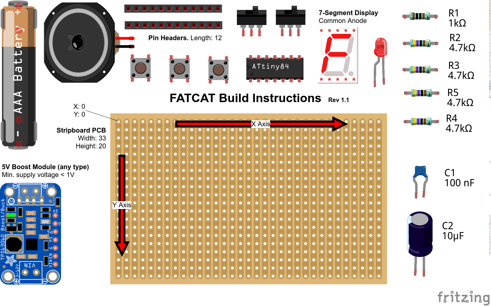
1Components
NOTE: The R1 value is chosen for a dimly lit, red 7-segment display. The R2 value is chosen for a dimly lit red LED. Experiment to find values for R1 and R2 that suites your preference.
![]()
-
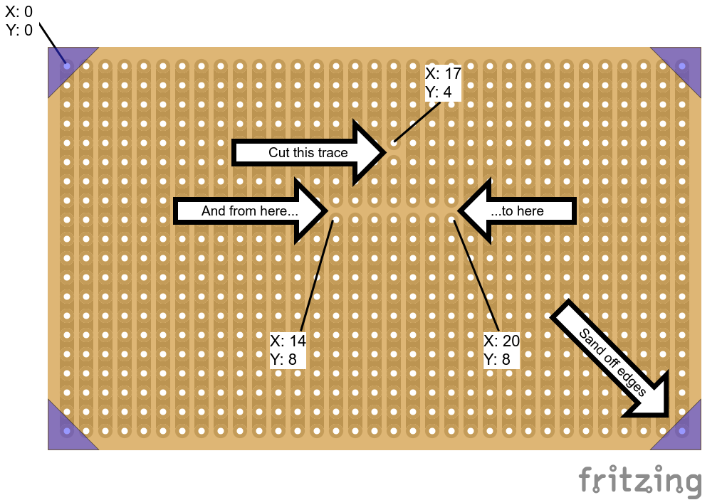
2PCB preparation
NOTE: The PCB is shown with traces facing down.
![]()
-
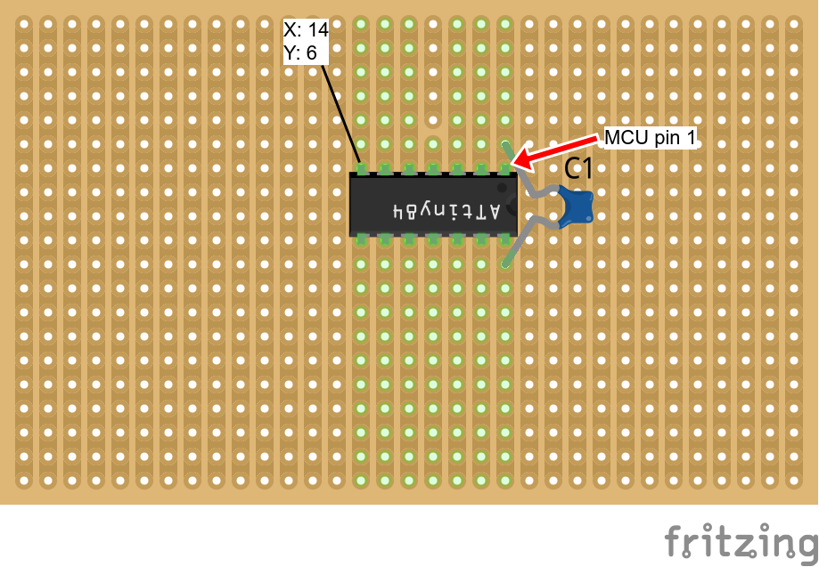
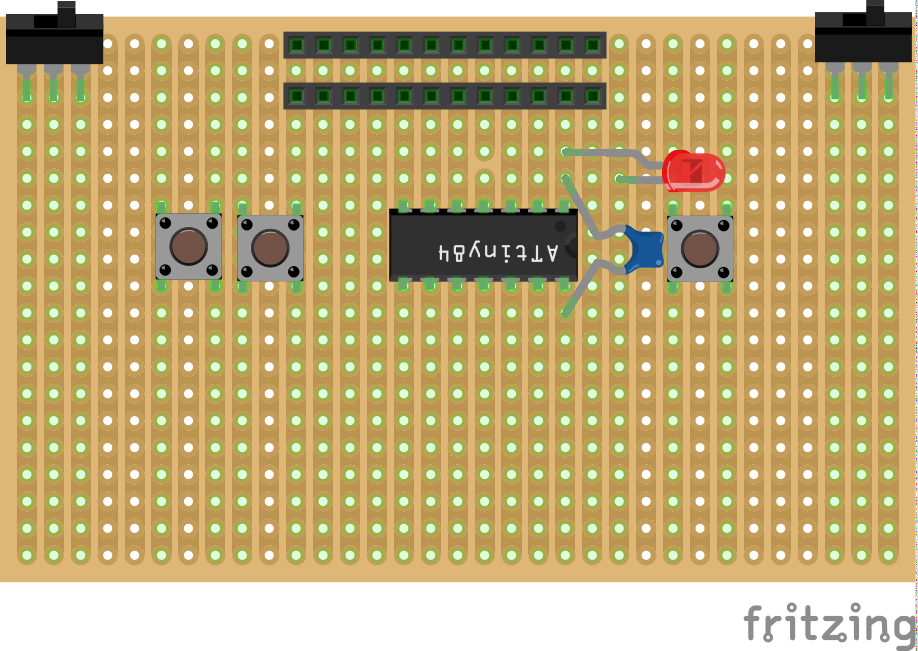
3MCU and ceramic cap
![]()
-
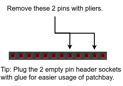
4Pin header preparation
![]()
-
5Switches, inputs and LED
![]()
-
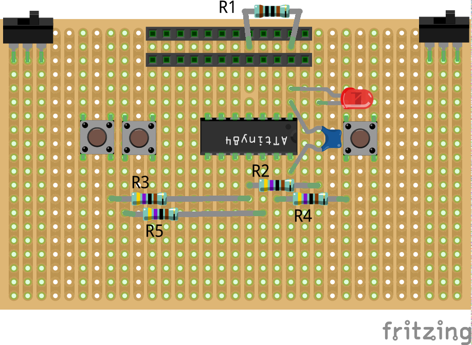
6Resistors
![]()
-
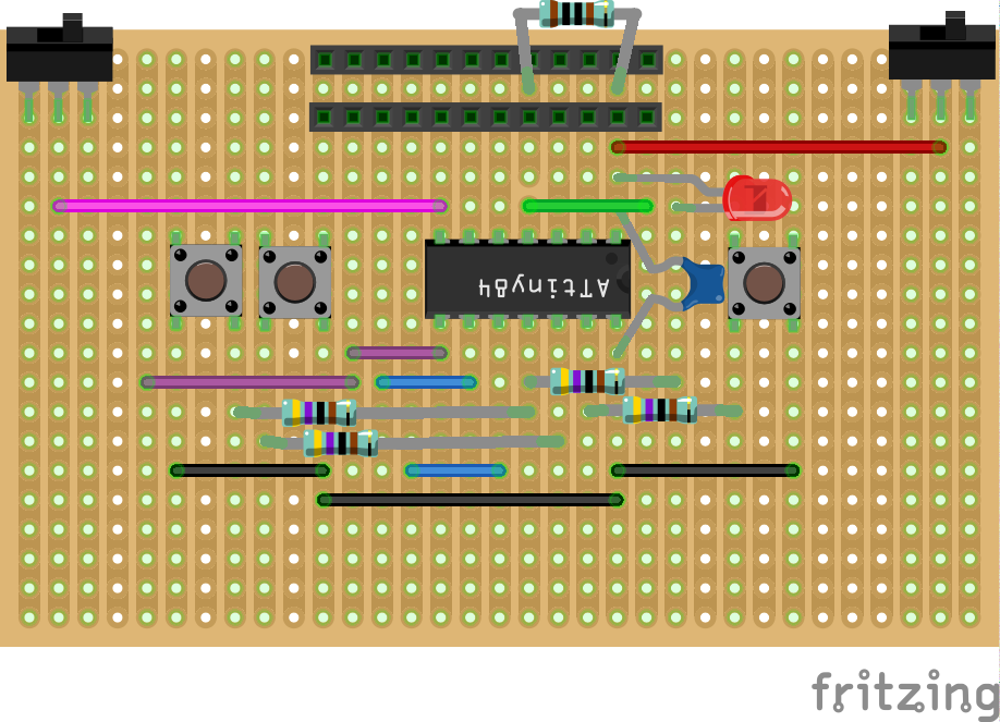
7Wires
![]()
-
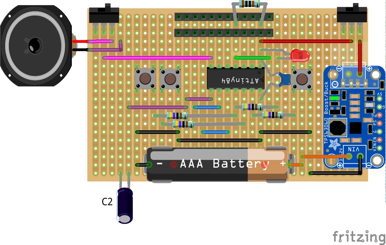
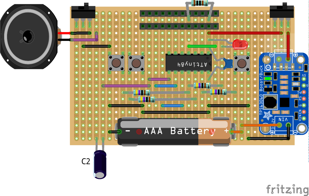
8Speaker, electrolytic cap, battery holder, boost module
The speaker terminals should be connected to the opposite side of the PCB.
Before soldering the speaker permanently, use a multimeter to measure it's current draw from MCU pins 7 and 8. If current draw on each pin exceeds 40 uA, use the configuration in the next slide (step 9) instead.
![]()
-
9Alternate speaker configuration
With this configuration only MCU pin 8 connects to the speaker. The other speaker terminal connects to ground.
![]()
-
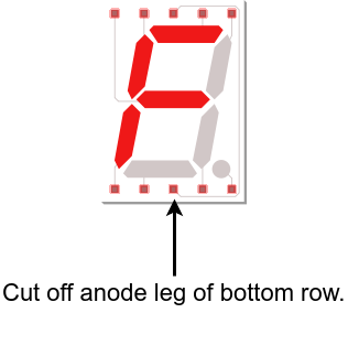
10Modify 7-segment display
![]()
FATCAT: Altoids Tin Mod Tracker
A drum machine, base synth and arpeggiator that fits in your pocket. User interface inspired by classic mod tracker software.
Discussions
Become a Hackaday.io Member
Create an account to leave a comment. Already have an account? Log In.