 audreyobscura
-
1Tools and Materials
![Tools and Materials]()
Here is everything I used
Consumables:
- Ultraviolet (UV) LED strip
- Foil insulation
- 12v 5A power supply
- Blue masking tape
- Clear packing tape
- 18 AWG speaker wire
- 22 AWG stranded wire
- solder
- heat shrink
- PCB
- Size M power connectors
- (8x) 24" lengths of 1/2" PVC pipe (for the frame, you don't have to use PVC, I just happen to have a LOT of it lying around)
- (4x) 1/2" PVC 3-way elbow joints
- (4x) A-clamps
Tools
Notes on materials:
A lot of this I had lying around. This may not be the most practical solution, but I made it practical for what I had. If you want to check out why I had so much PVC - check out my free class on PVC construction!
I used the foil insulation as a backer for the LED strips. I know this material could be rigid, but also collapsible. If you can think of another way to back this project with a different material that you have lying around, by all means, use that. I will say, the foil insulation is surprisingly tough, and stands up great to manipulation and rolling!
-
2Cutting, Spacing, and Marking the Backer
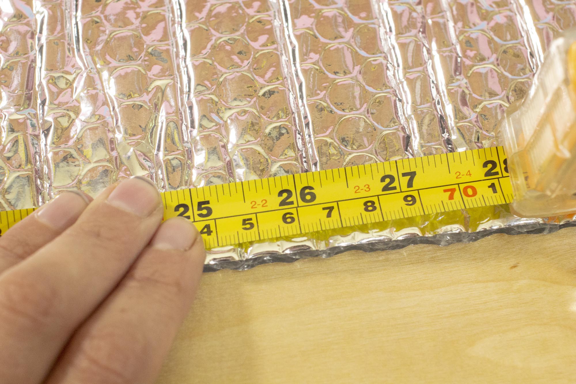
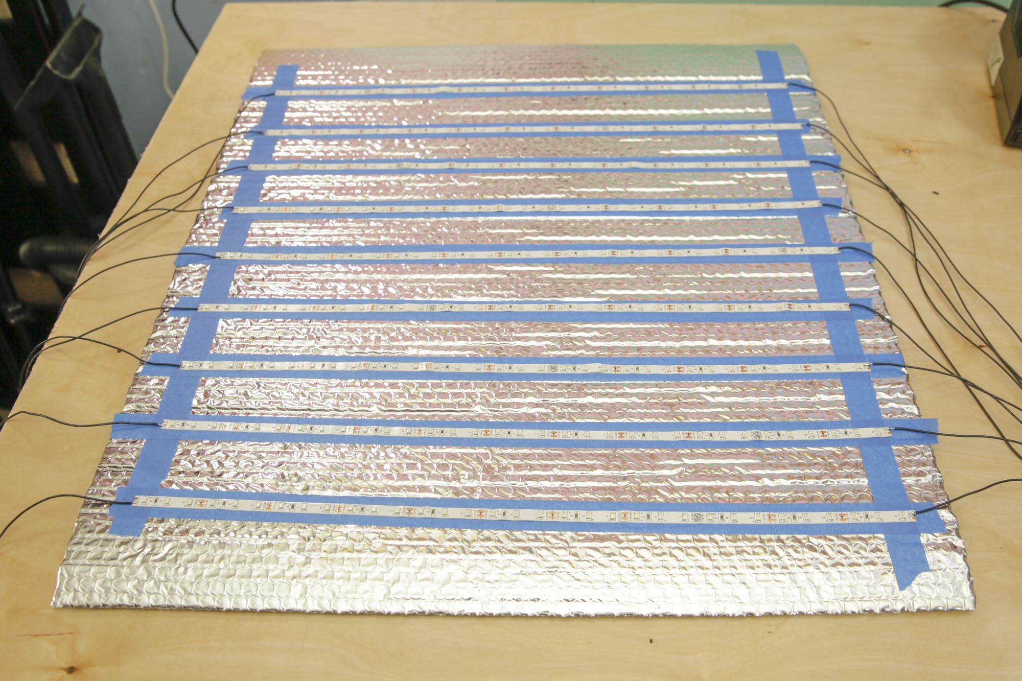
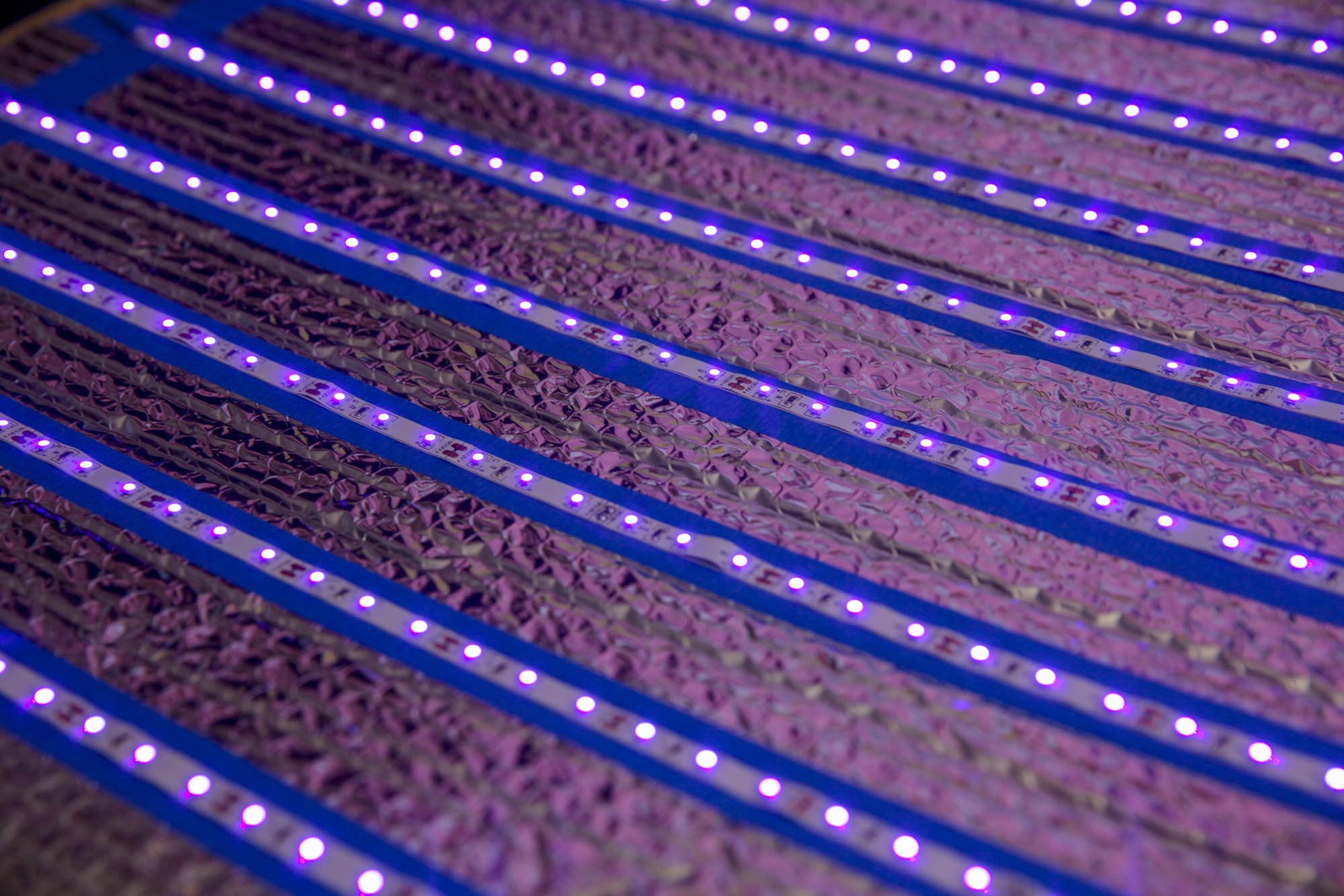
Given the length of the roll of LEDs, and the width of the roll of insulation, I decided to cut 9x 21" strips of UV LEDs. I did some math and figured out I would want to space them about 2.75" apart - I was concerned if they were any further and it may begin to affect the quality of the light being emitted.
![]()
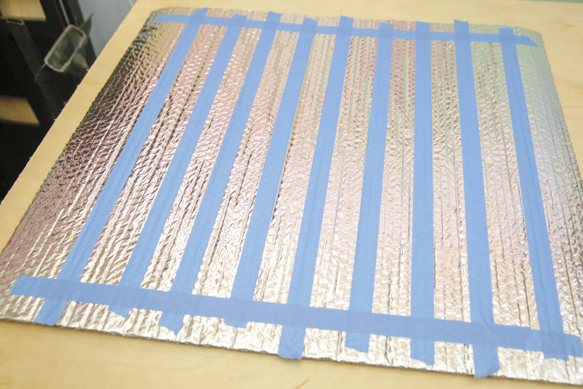
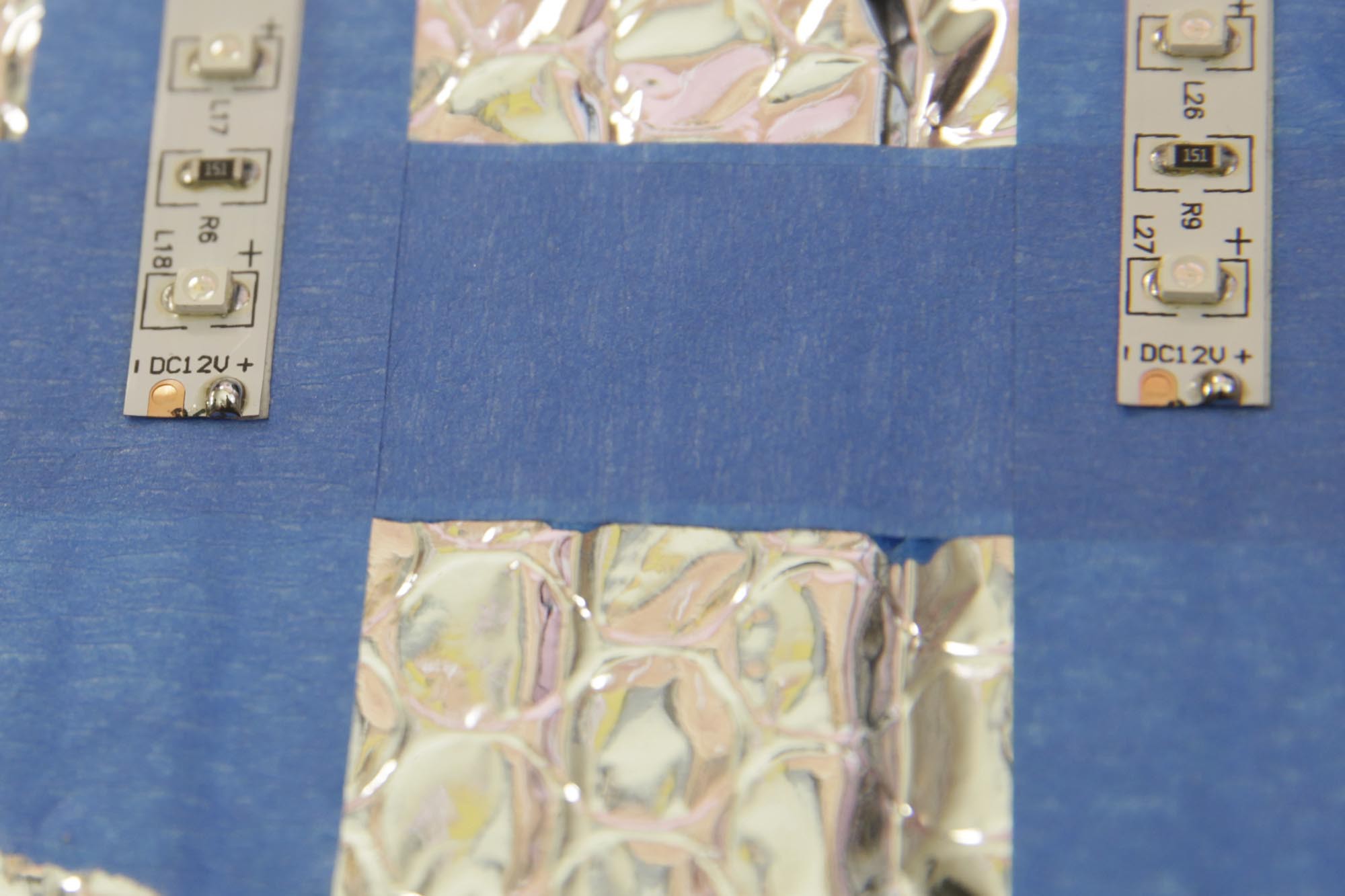
From experience, I know that the LED strips WILL NOT stick well to the mylar sides of the foil insulation, but the adhesive backing on the strip does stick to masking tape.
![]()
I measured out the distance I could span with the 9 strips, and made some marks as to where I wanted the tape backer strips to be placed.
I ended up with a pattern for a 21"x21" square of LED strips made.
![]()
-
3Cutting and Placing the LED Strips
![]()
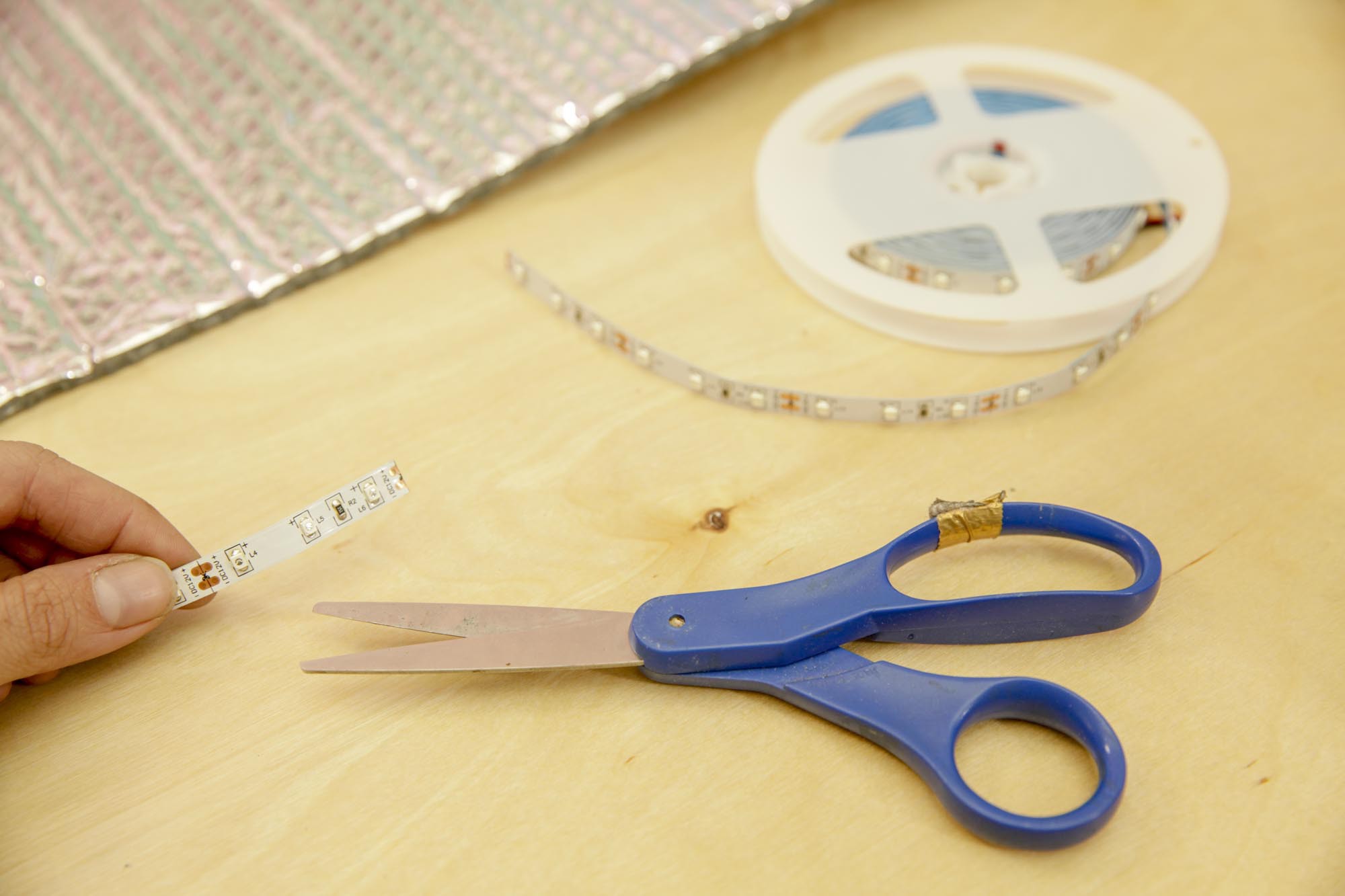
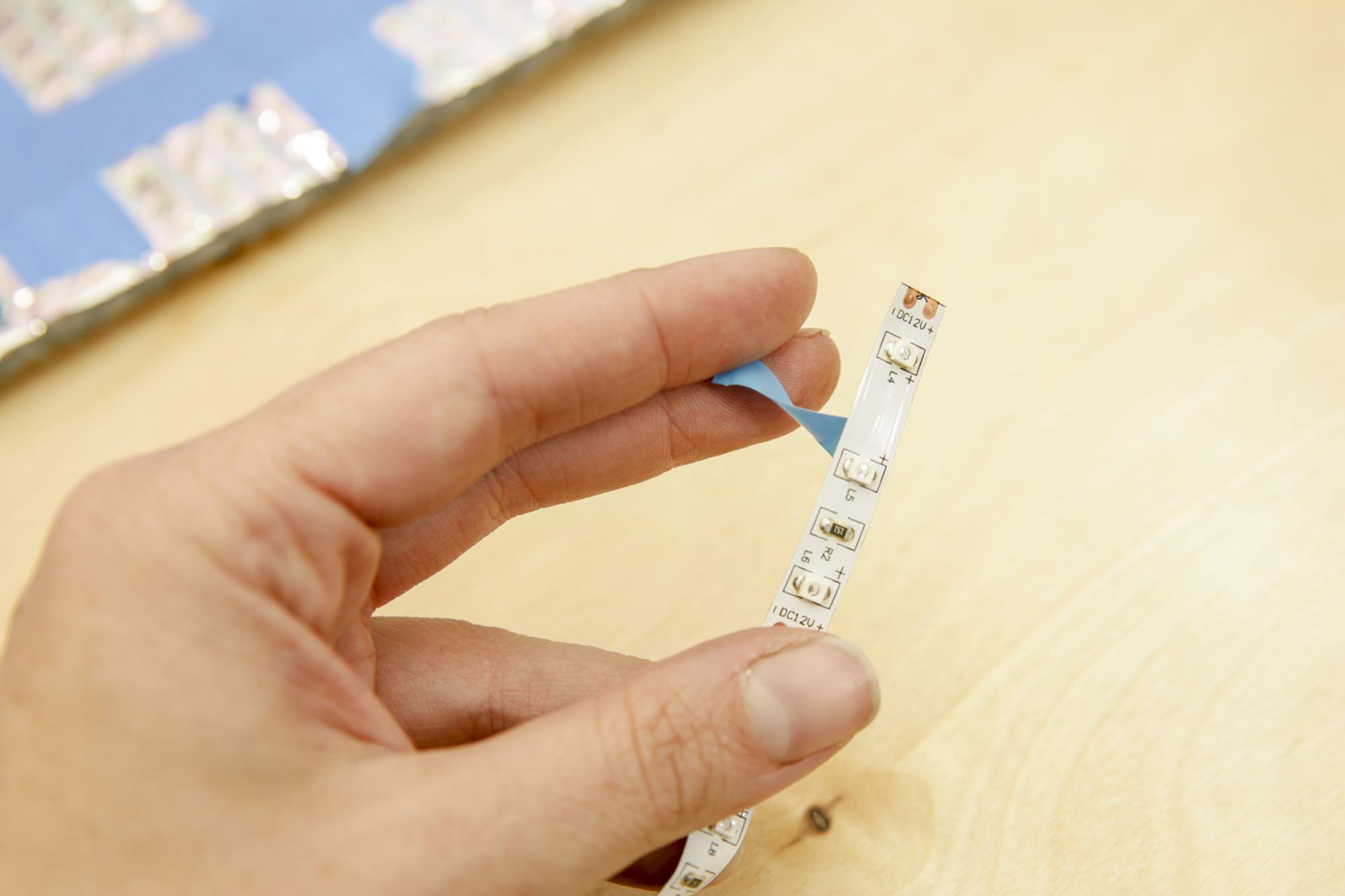
Cutting apart the LEDs is SUPER EASY. The roll has designated spots to cut every 3 LEDs. Where you slice the LEDs also becomes the soldering junction.
![]()
Next up was removing the strip for the LEDs adhesive backer and pressing the strips into the lamp's surface.
![]()
![]()
I really squished the strips down quite a few times to make sure that the tape and the LED strips were completely bonding and I wouldn't have to worry about strips slumping off while I was trying to use the lamp.
-
4Adding Wire Leads to the Strips
![]()
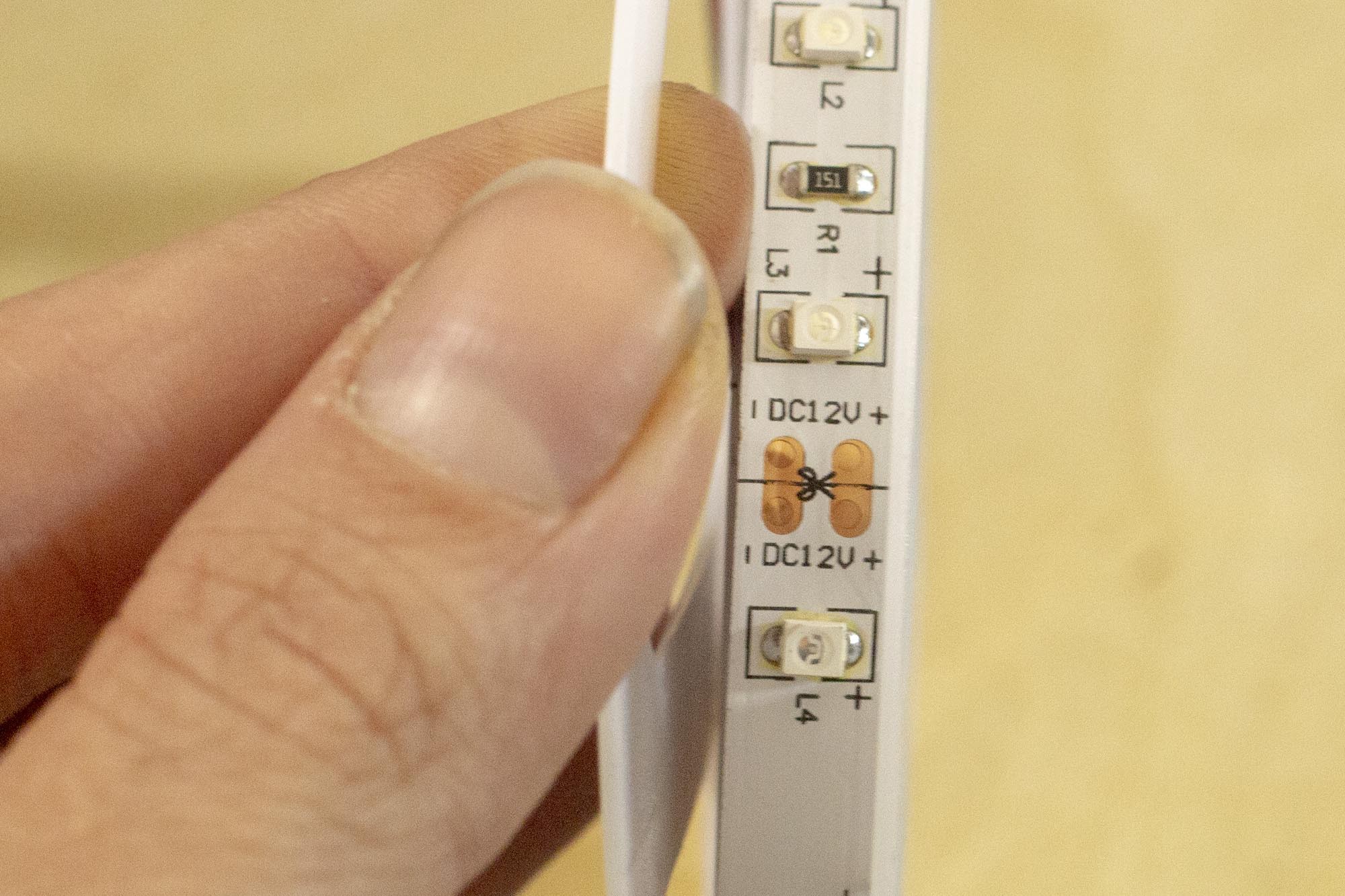
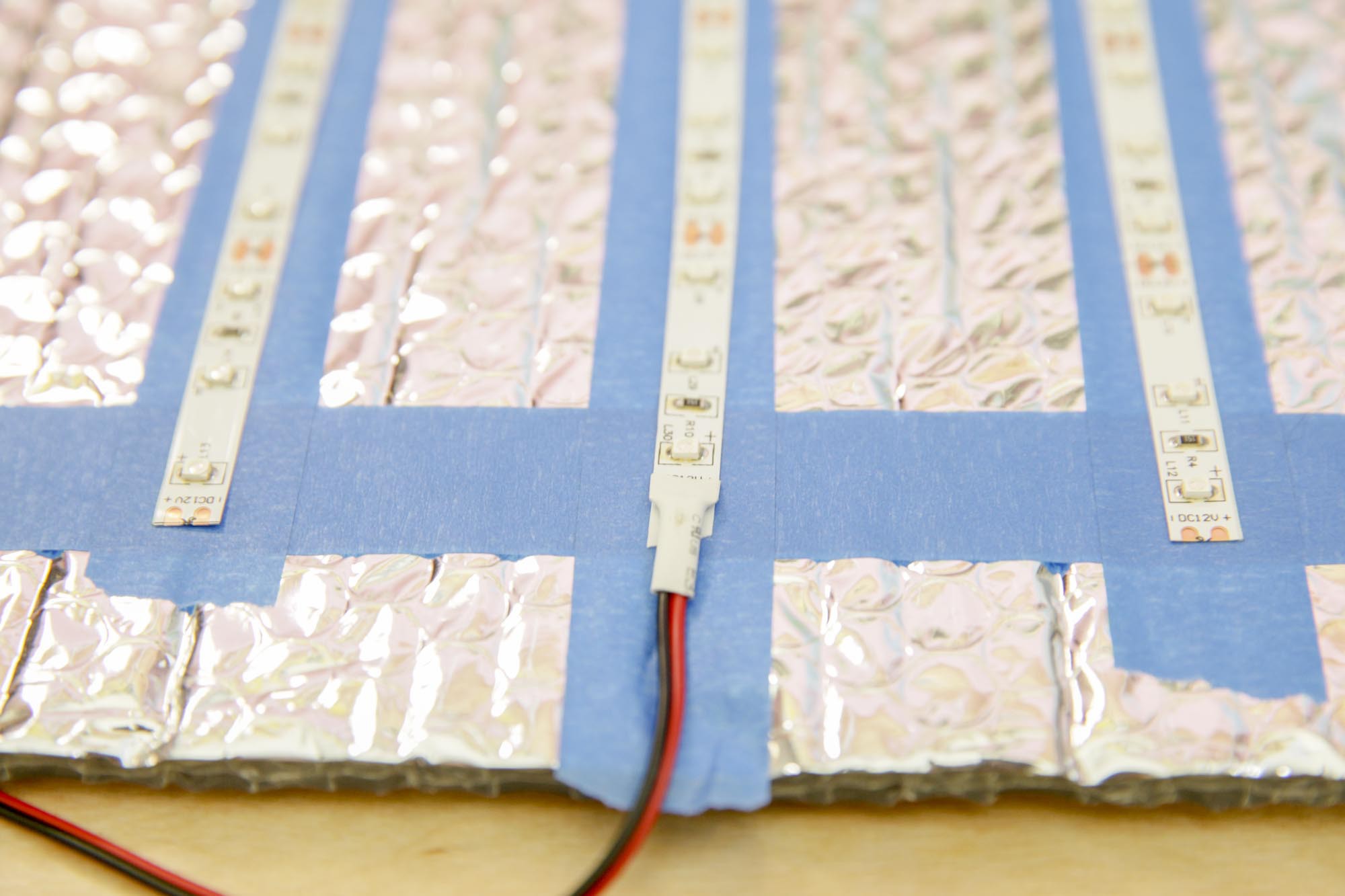
There was only one wire junction on the LED strip, at the beginning of the strip, and since I cut the LED strip into many segments, I needed to add more wire junctions to run power to the LEDs.
![]()
I began by cutting down the length of wires I would need - two lengths per strip, each pair longer than the last to meet at the PCB power junction after these were connected to the strip.
![]()
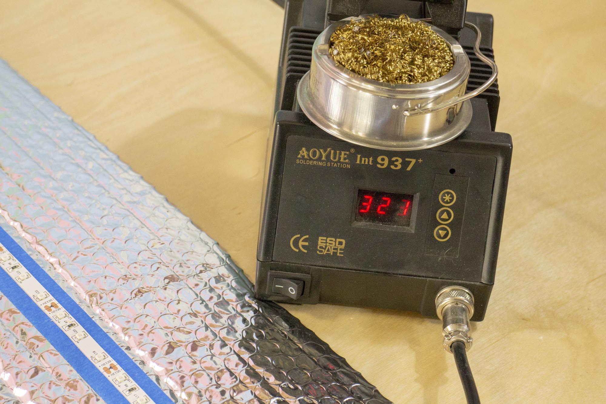
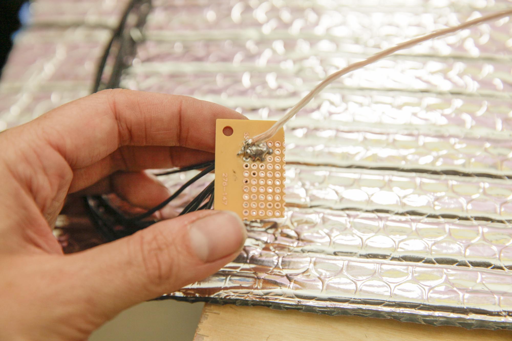
I set my soldering iron just hot enough to melt the solder, but not so hot that it would burn the plastic or mylar foil while I was making the connection. If you're soldering iron doesn't have variable heat, you may want to complete this step before attaching the strips.
![]()
Soldering to LED strips can be a fickle thing, so to save time and be able to work more nimbly, I tin the component contact and the wire separately, then make the connection by quickly melting the two together. ( See YouTube video in the intro description for better demonstration)
-
5Wire Management
![]()
"NO MORE HANGING WIRES!" -Mombot
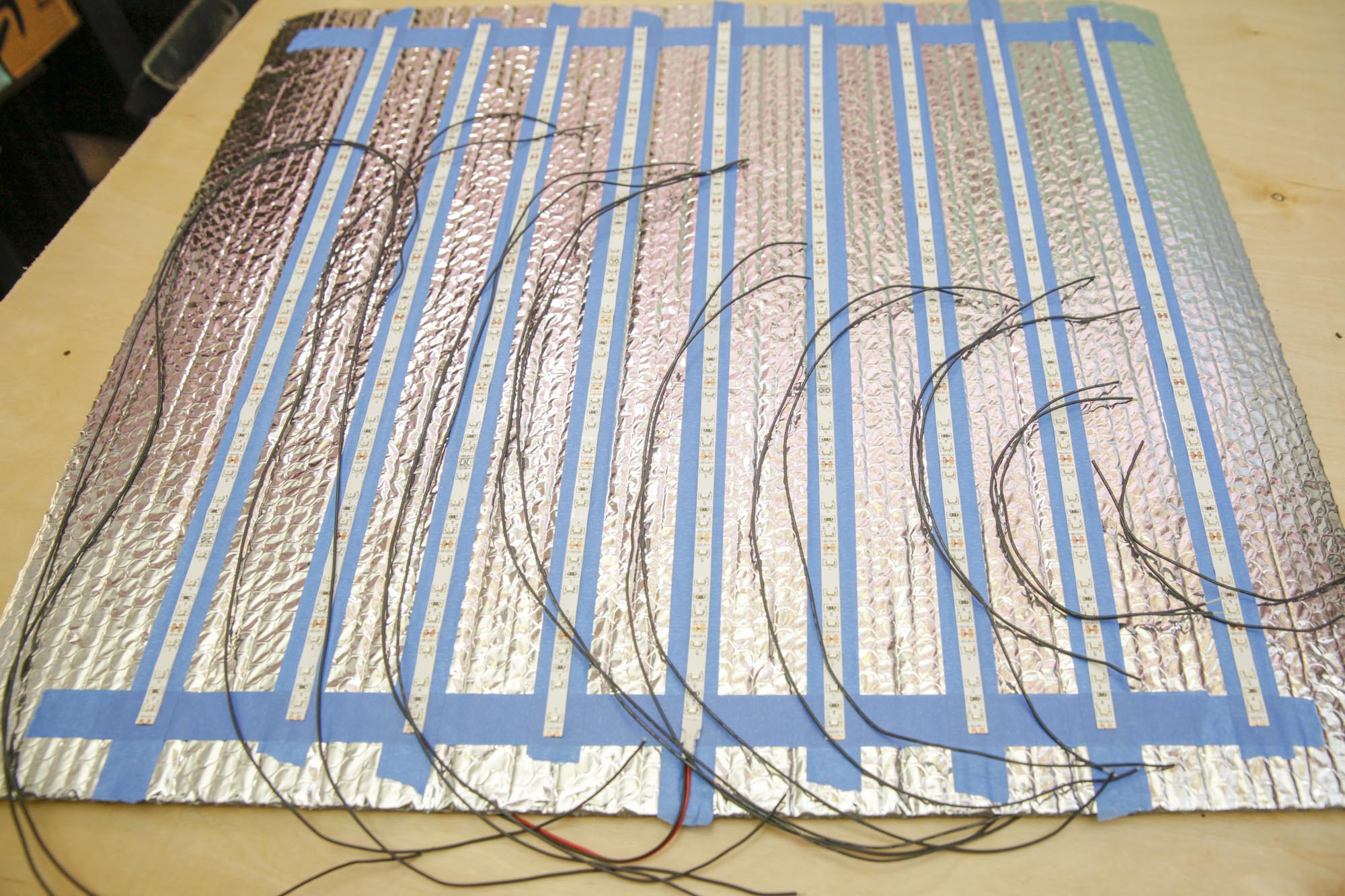
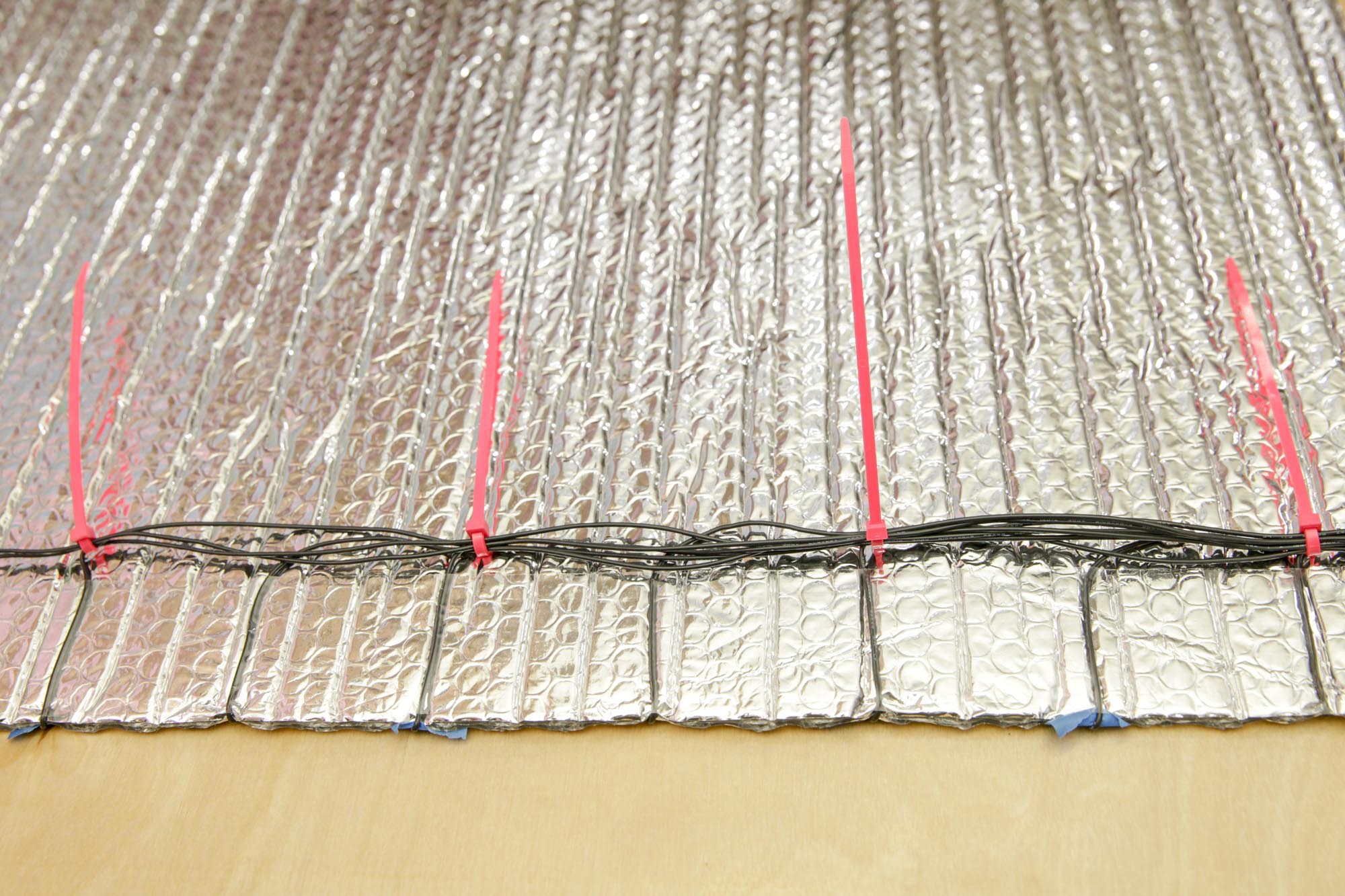
Cable management is key for projects like this where18 long spindly wires are flying around, so I use zip ties to make sure my connections wouldn't be swinging all over the place.
![]()
![]()
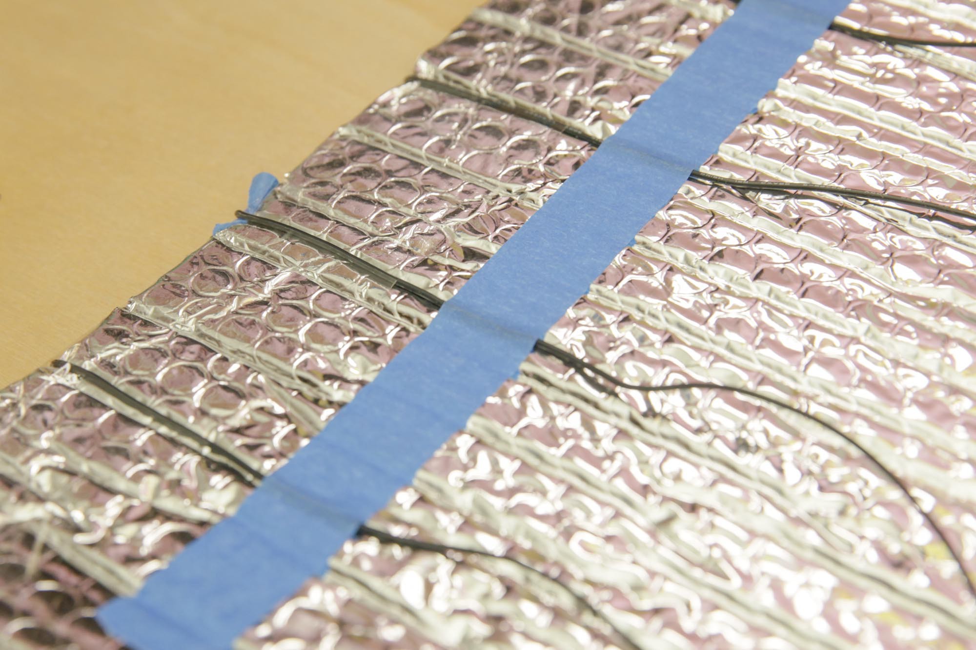
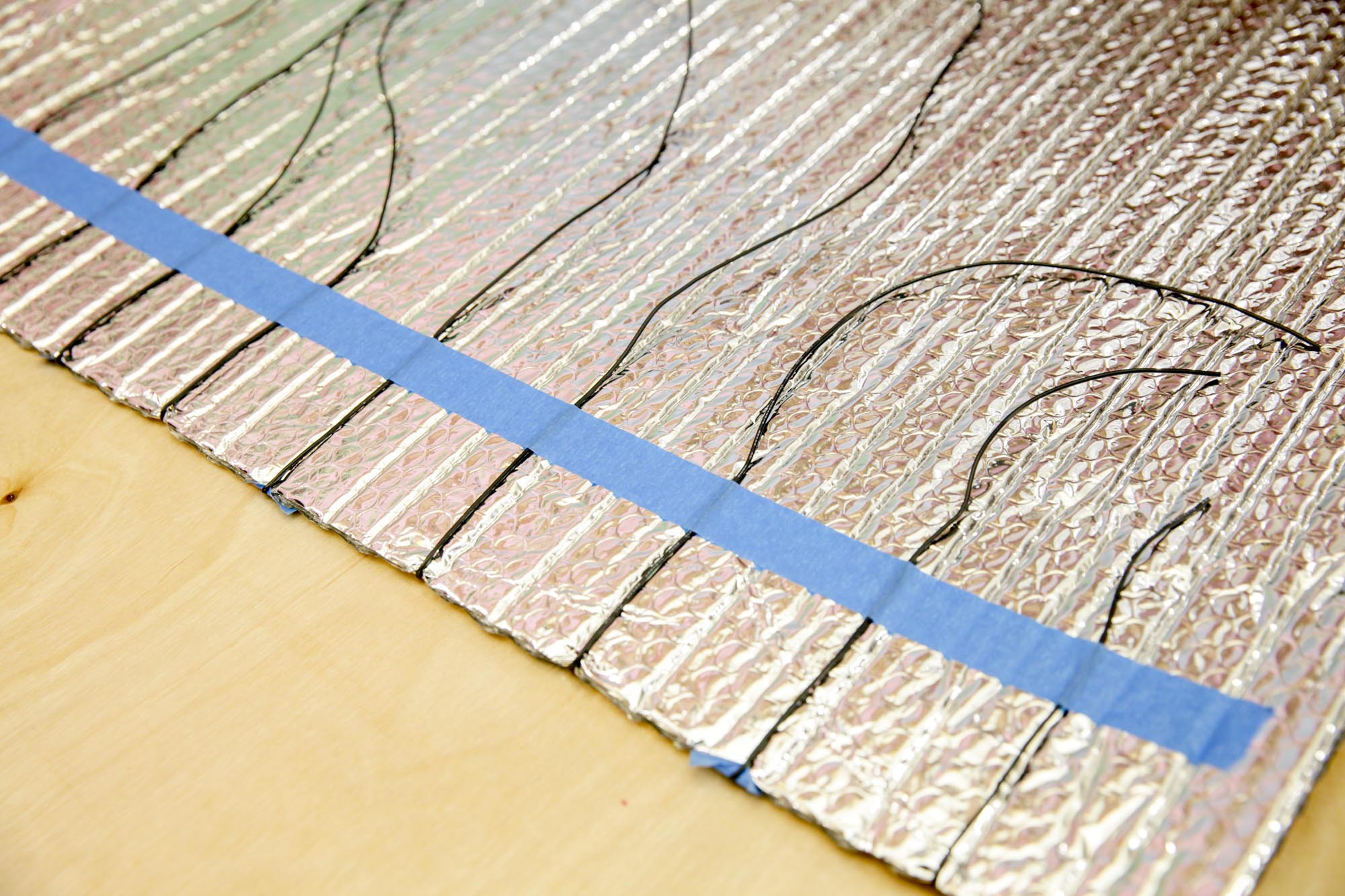
Using trusty masking tape and clear packing tape, I was able to come up with a pretty clever solution. I just folded the wires back over the other side of the insulation, 'pinned' them with masking tape, and then secured them with 2" clear packing tape. It's hard to tell it's there in the photos, but I promise, it is.
![]()
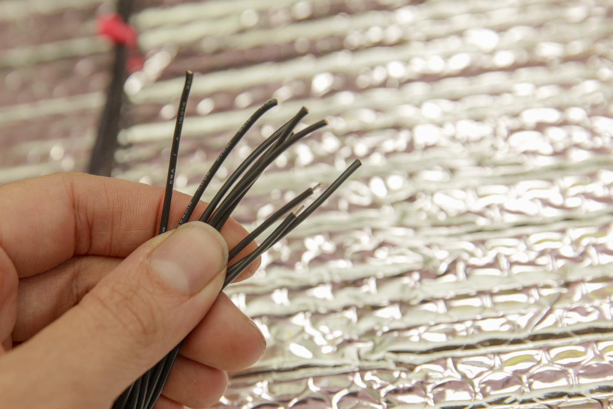
Once the wires were more or less secured, I went down each side of the lamp and secured the wires into bundles so I was left with two bundles, one on each side for 12V+ and ground connections.
![]()
![]()
Lastly, each side needed a haircut before it could get attached to the PCB. The wires were made to be the same length and then prepped to be connected to the PCB.
-
6Connecting to PCB
![]()
![]()
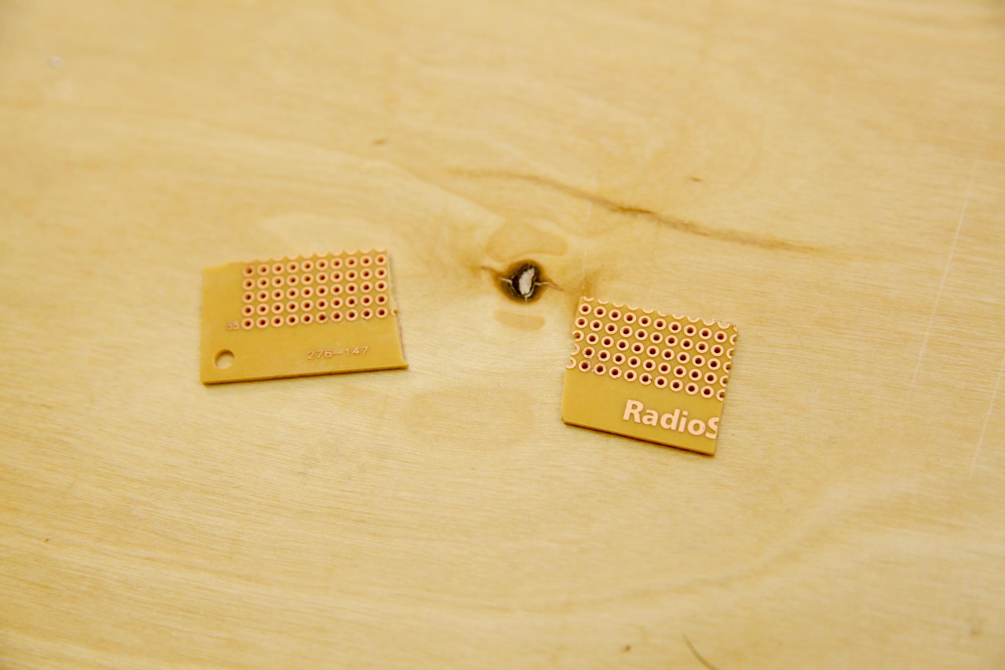
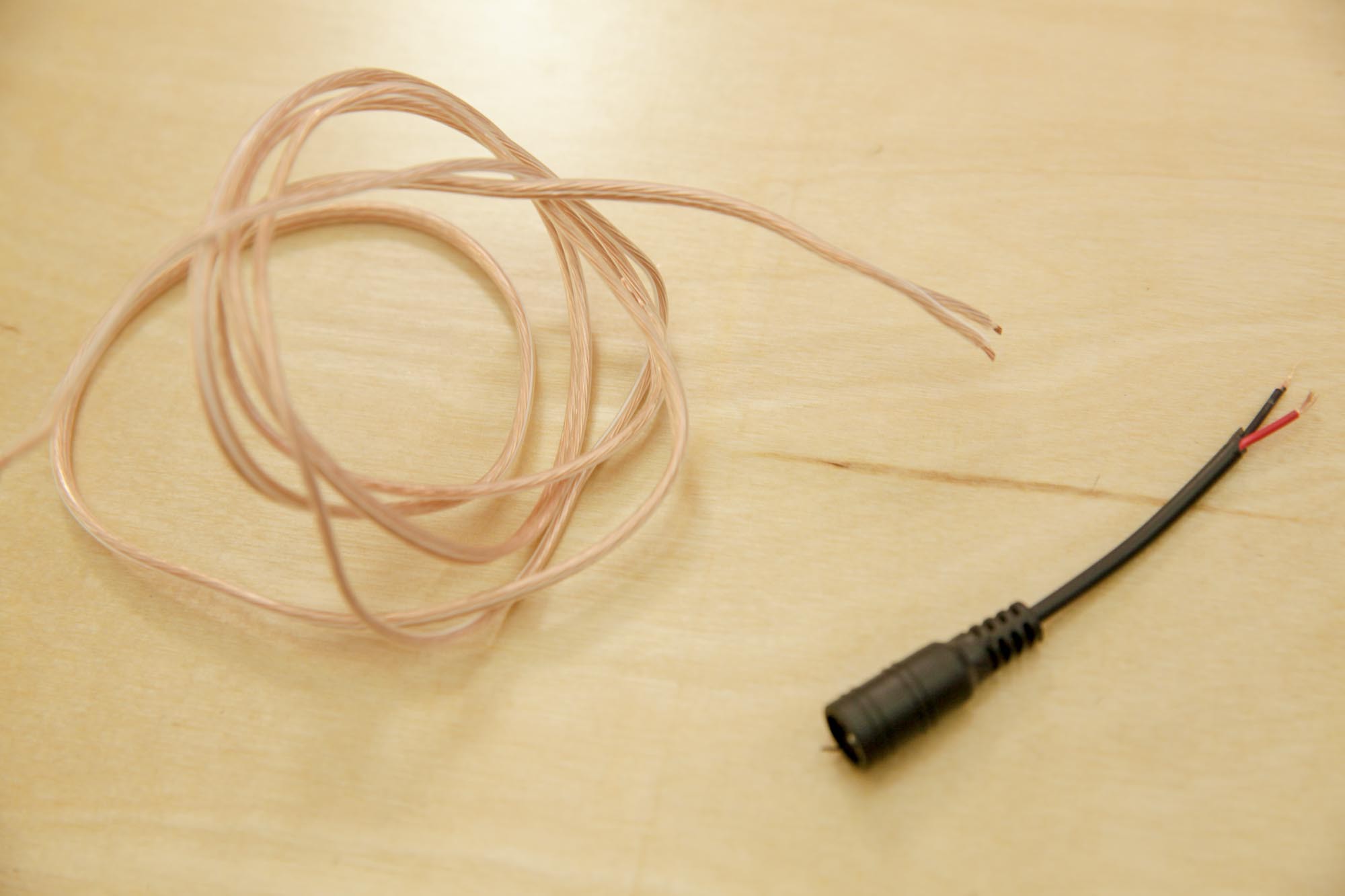
I sliced up some plain PCB, and cut down a short length of 18 AWG speaker wire (in retrospect, I wish it was longer)
![]()
![]()
Next, I soldered all of the thin wires from the LED strips into a cluster on the circuit board. Then I connected the tinned speaker wire to the cluster.
![]()
![]()
I did this for each side of the lamp, one PCB was for the 12v positive rail of connections, then the ground rail on the other side of the lamp.
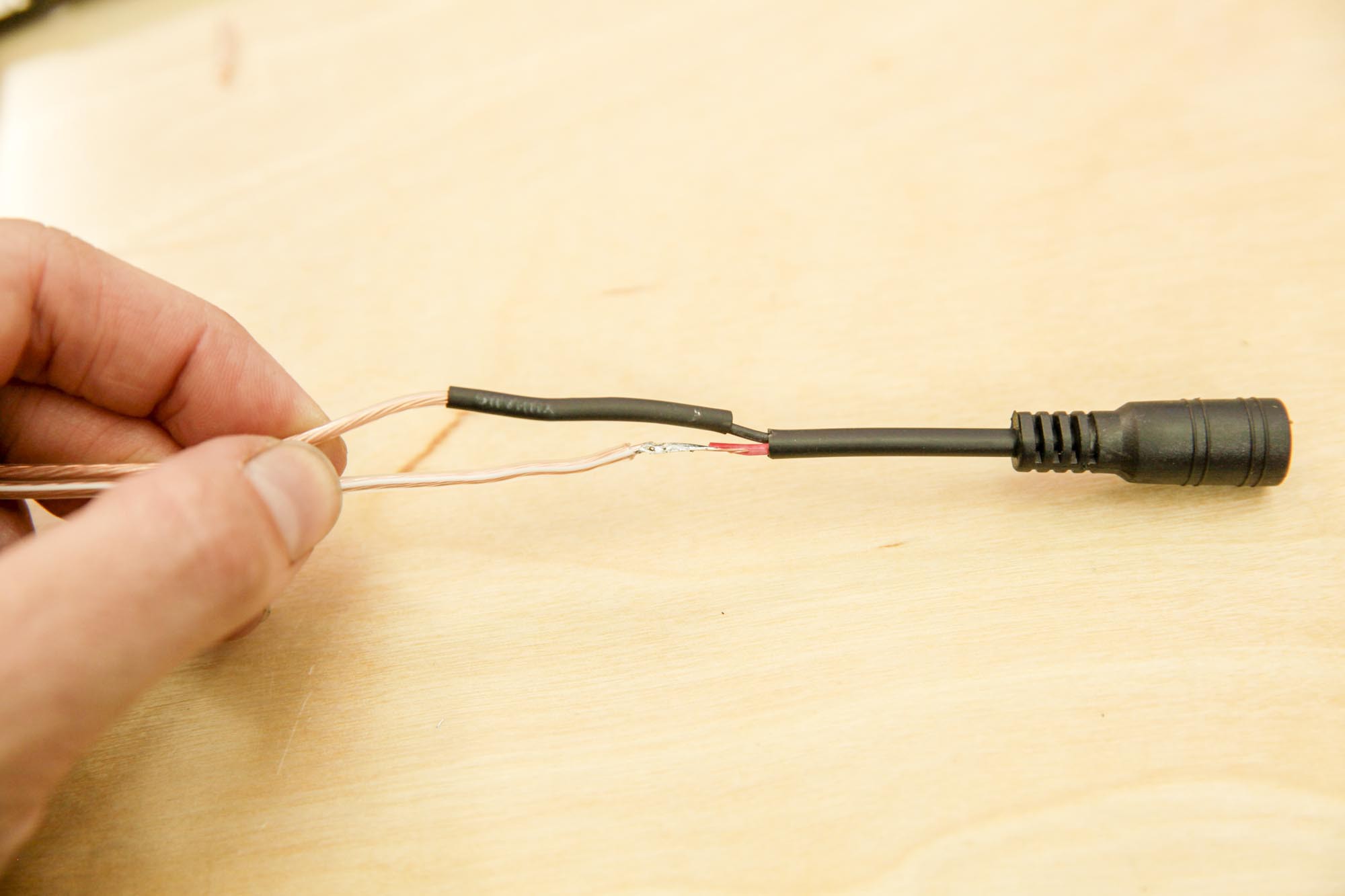
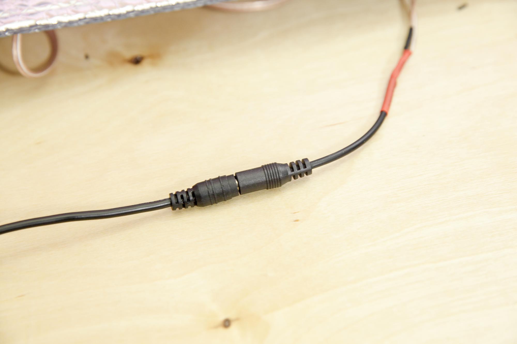
Using shrink-tubing and heat gun, I encapsulated the solder junction where the other end of the speaker wire was soldered to the power connector.
-
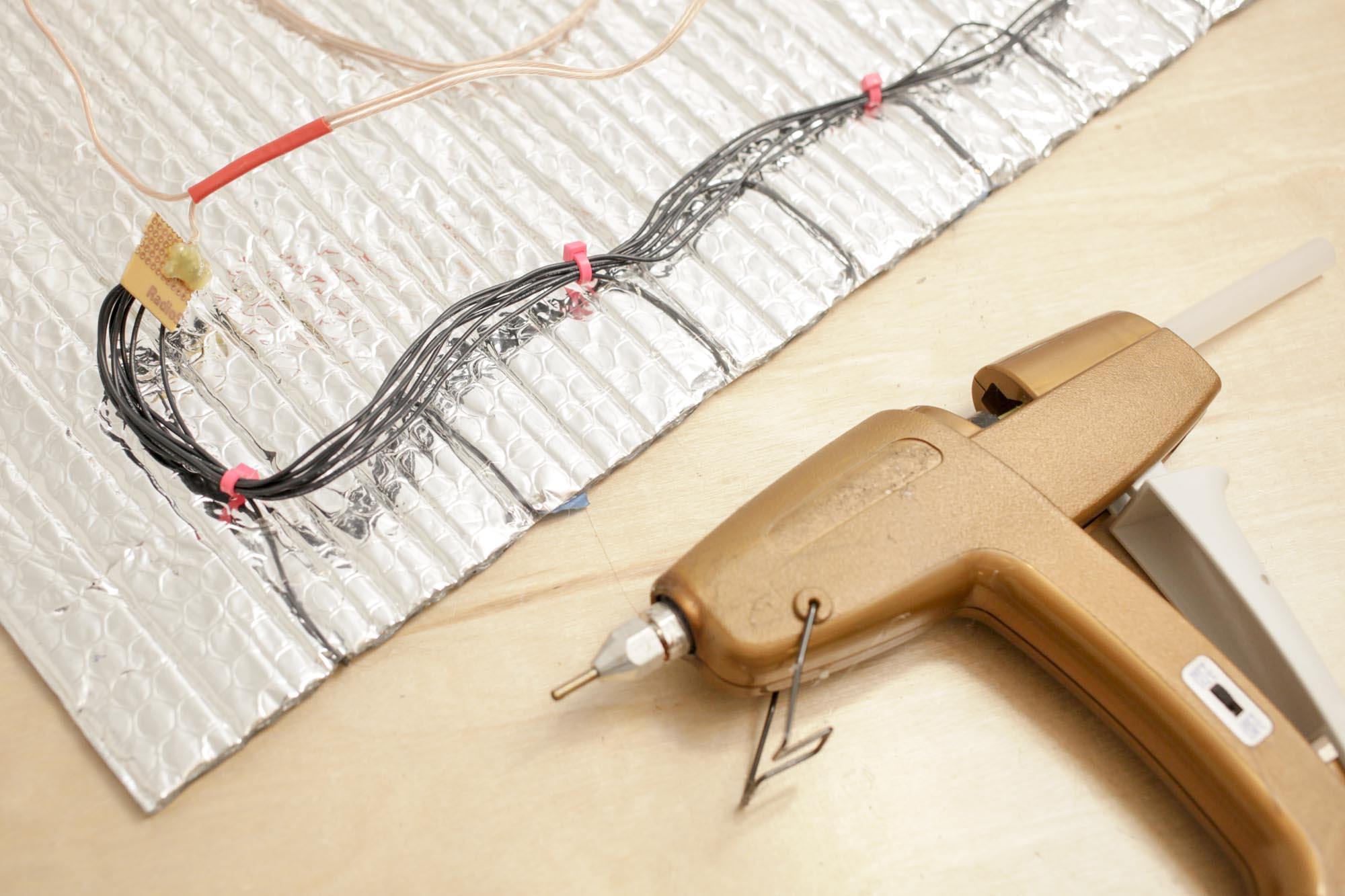
7Testing and Sealing the Circuit
![]()
![]()
After testing all of the circuit connections, I made sure I hot-glued my connection points, so that I would never risk shorting the circuit.
![]()
It's a cheap but effective way to protect a circuit. I know people that have 'waterproofed' things this way.
¯\_(ツ)_/¯
-
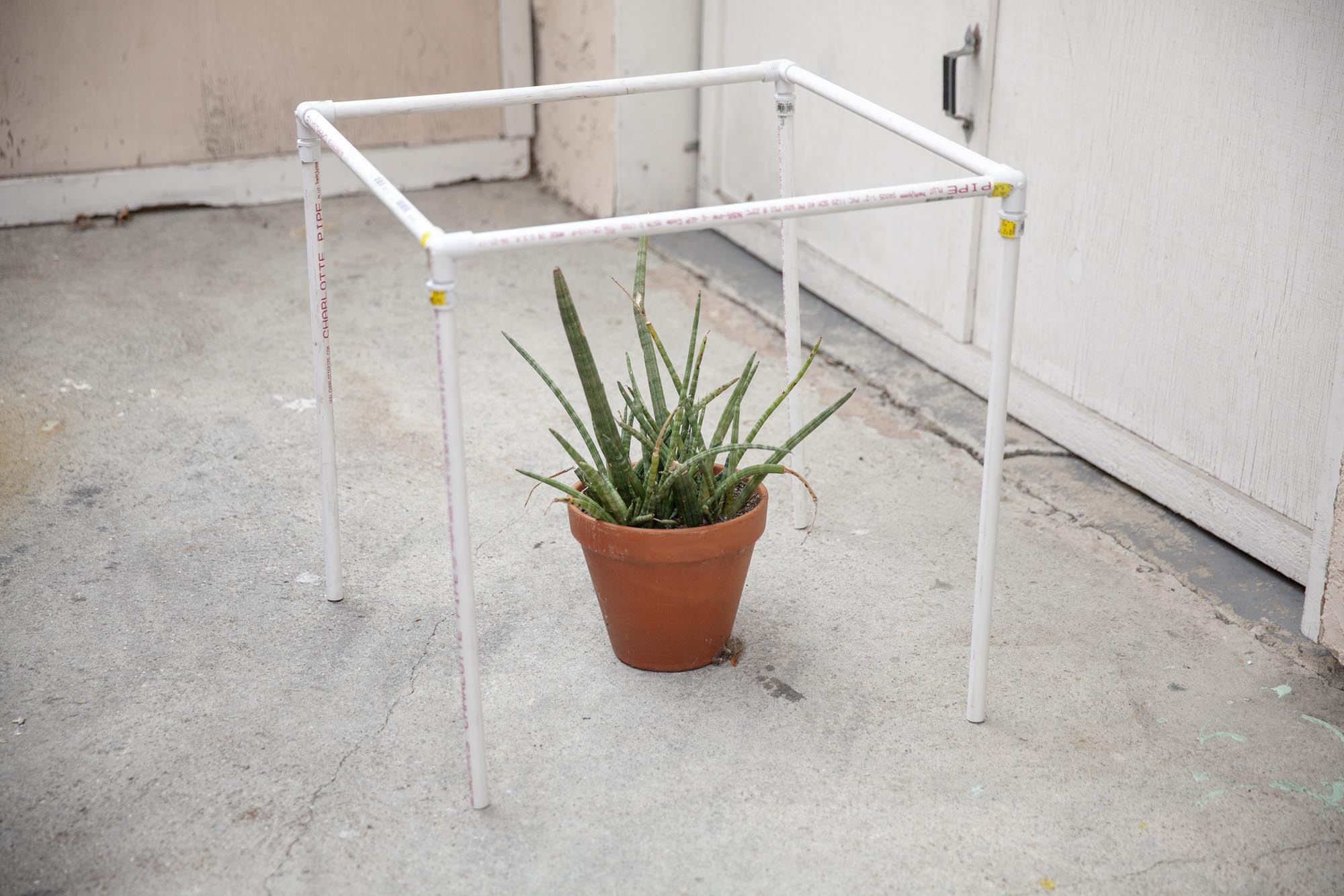
8Building a collapsible frame
![]()
I constructed a quick PVC frame for the lamp by connecting 8x 2' lengths of 1/2" PVC pipes with 4 3-way elbows. All of the lengths were 2' long. It makes storing and reusing these posts really easy. Here it is with a plant in front of the garage for scale.
![]()
After the frame was constructed, I was able to secure the flexible lamp to the frame using A-clamps, and connect the lamp to power.
![]()
I moved studios in the middle of this project, so here is a much more pleasant gif of the lamp in action.
![]()
The best part of this project is that this lamp just rolls up and stores easily for future use. Perfect for tiny studios like mine.
I'd love to know what you would use a UV light like this for - let me know in the comments!
___
If you want to see what else I'm up to in my workshop, follow along with me on Instagram, Twitter, and YouTube.
Thanks for taking the time to read about this project, I'll update it again once my UV resin tests are completed.
Collapsible UV LED Lamp + Resin Oven
This tutorial goes over the making of a collapsible UV light, made from UV LED strips, and a flexible-but-rigid foil + air backer.


Discussions
Become a Hackaday.io Member
Create an account to leave a comment. Already have an account? Log In.