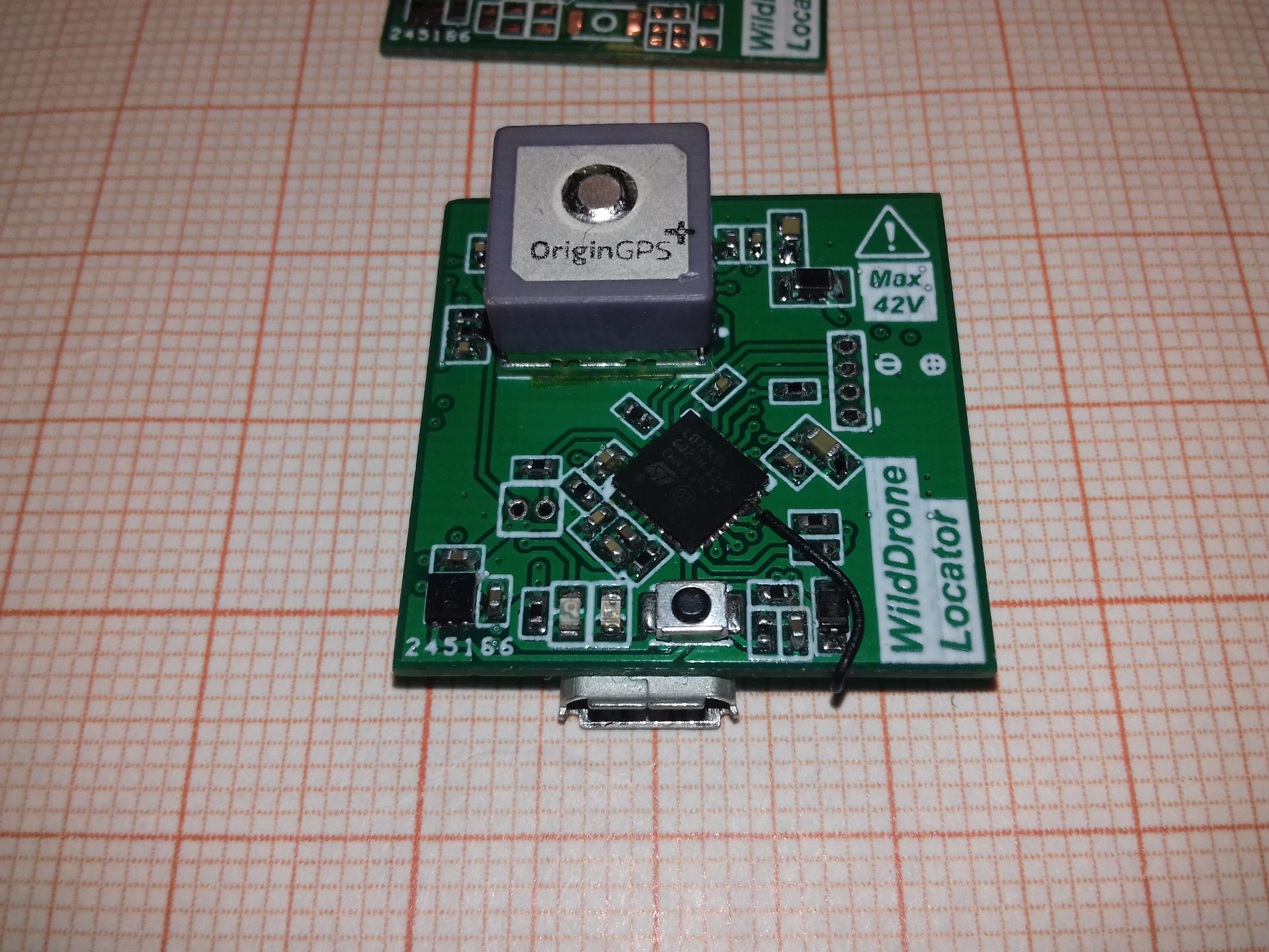
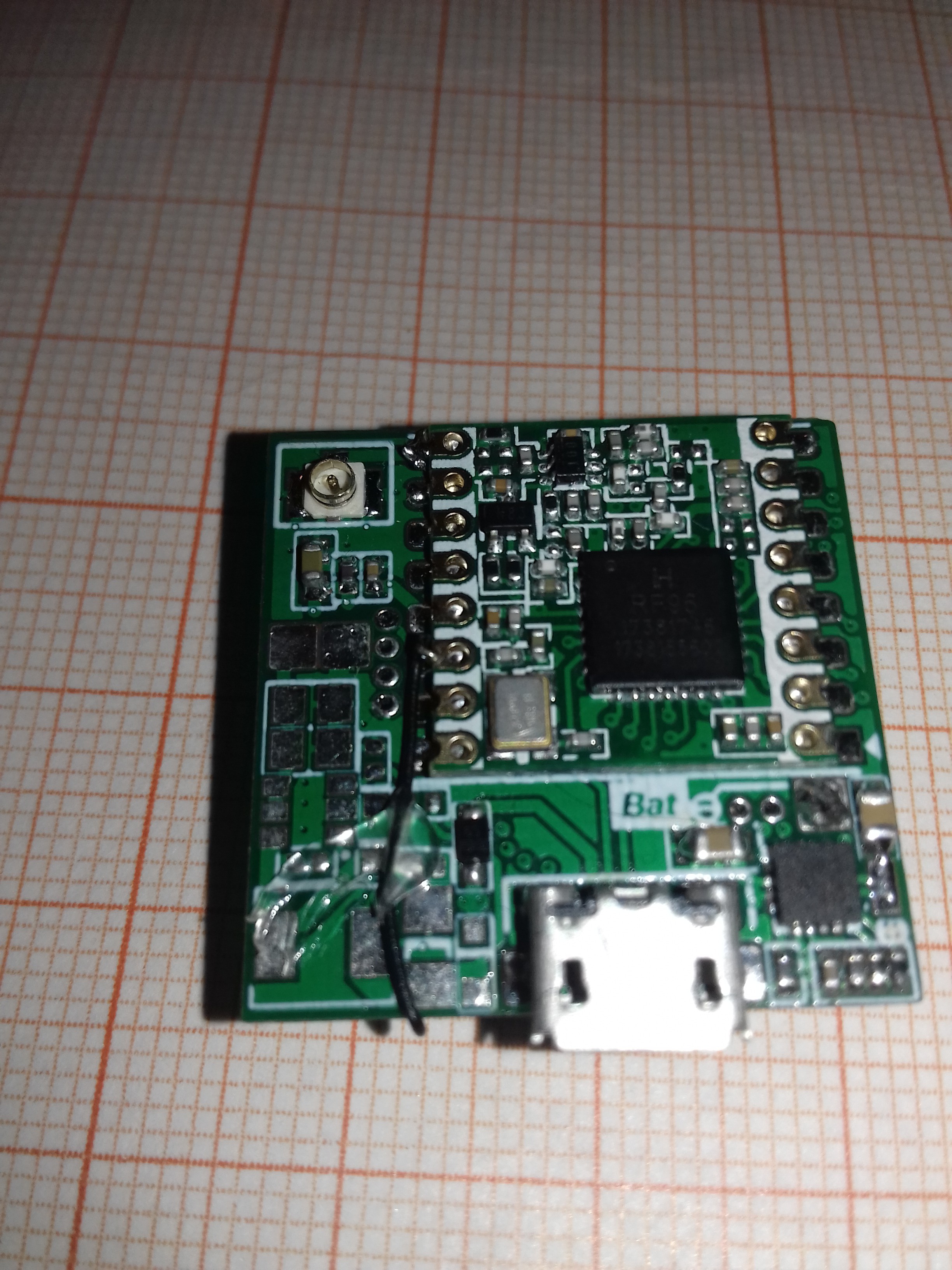
Took me almost an entire day to mount all 67 components.
An of course there had to be a bug. In fact two:
- If you look carefully at the bottom of the GPS module, you will see a bit of yellow kapton tape. It's because that huge pad below the component should have been covered with solder mask. And it's not. The module has some exposed metal pads below it, and they're not just ground pads.
- And that wire supposed to be included in the schematic. It connects DIO0 pin from the LoRa transceiver with a MCU pin (in this case PB11). DIO0 is the interrupt pin of the transceiver, and it signals various events to the MCU. I obviously found this out after sending the PCBs to the factory. Well, live and learn....


This particular board will be the receiver and it will be powered via USB, so the step-down converter is not attached (fig. 2, left side of the board).
Discussions
Become a Hackaday.io Member
Create an account to leave a comment. Already have an account? Log In.