-
1Designing the Board
The model for the board is created using a parametric OpenSCAD script. To run the script download and install OpenSCAD.
! IMPORTANT: All scripts are functional but still the code has to tidied up!
The OpenSCAD scripts can be found on Github. There are 3 different versions of the script:
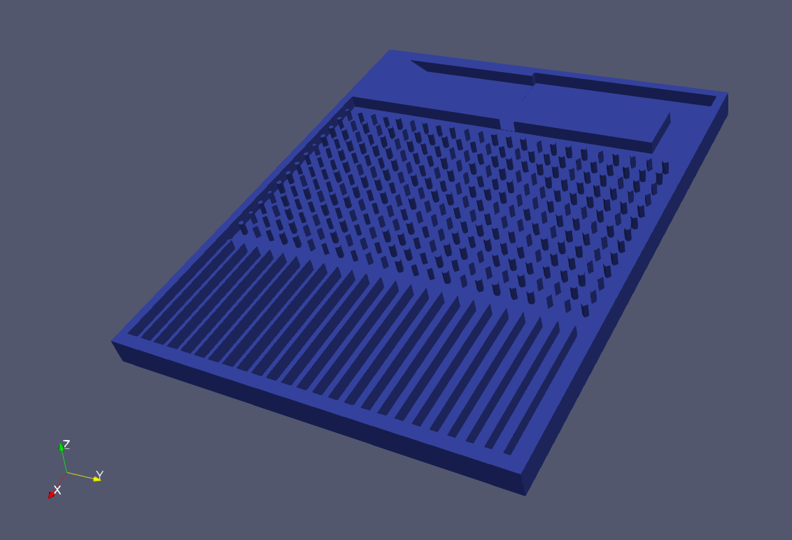
- version 1.0: This is the basic version of the board with no mechanical system for loop the bearing balls. The model does not included paths for the electrical wiring.
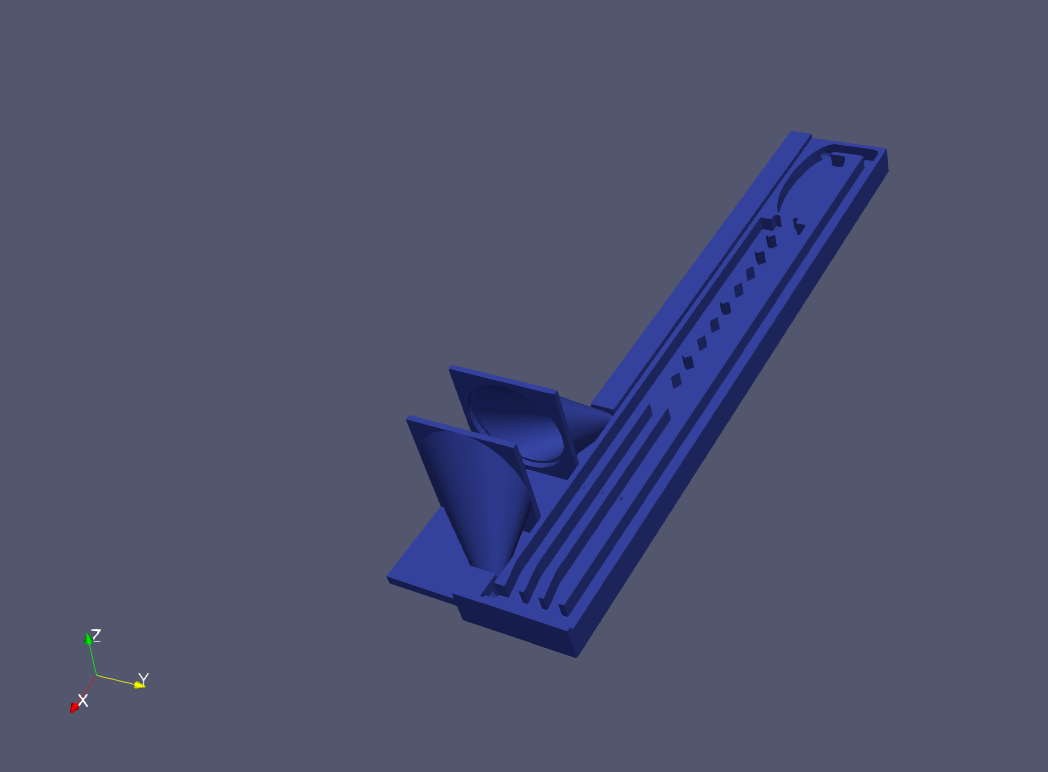
- version 2.0: the board is extended by funnel and tubing to felicitate the looping of the bearing ball by routing air of fan to push the balls. ---Not functional, at the current state! A bigger fan is needed---
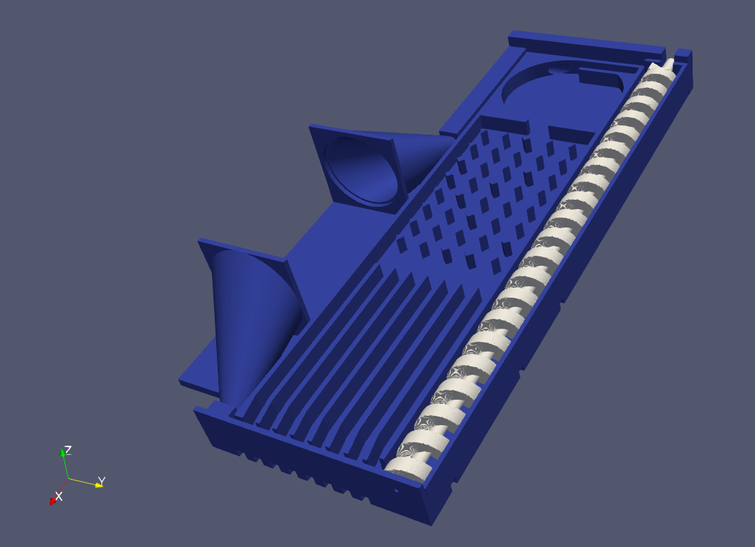
- version 3.0: the version 2.0 board is extended and modified by a mechanically driven spiral to move the bearing balls. The model comprises of two STL-models; The model for the board and the model for the spiral.
All scripts are parametric and can be modified to fit the geometrical function, the needed number of bins, radius of the bearing balls or size of the used printer.
The scripts use the following parameters to modify the board to the 3D-printer and the indented purpose. The following parameters are the most important to be set:
- [size_x, size_y, size_z] of the board
- bearing ball radius
- tolerance
Alternatively the the generated STL-models can be downloaded( version 1.1, version 2.0, version 3.0, spiral ) . the last to models are designed for using a bearings balls radius of 2.25 mm. The pre-render models are intended to be printed using the Creality Cr-10s 3D printer.
![]()
Version 1.1 ![]()
version 2.0 ![]()
version 3.0 -
2Preparing the printed model
After the printing the model should be cleaned so that no extra printed material is in the path of the bearing balls.
![]()
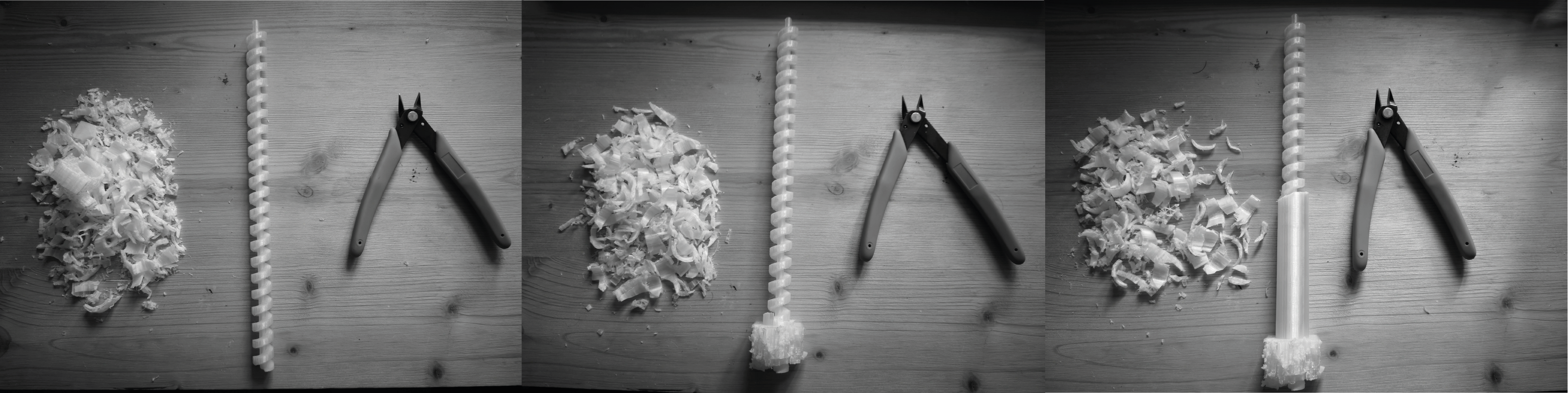
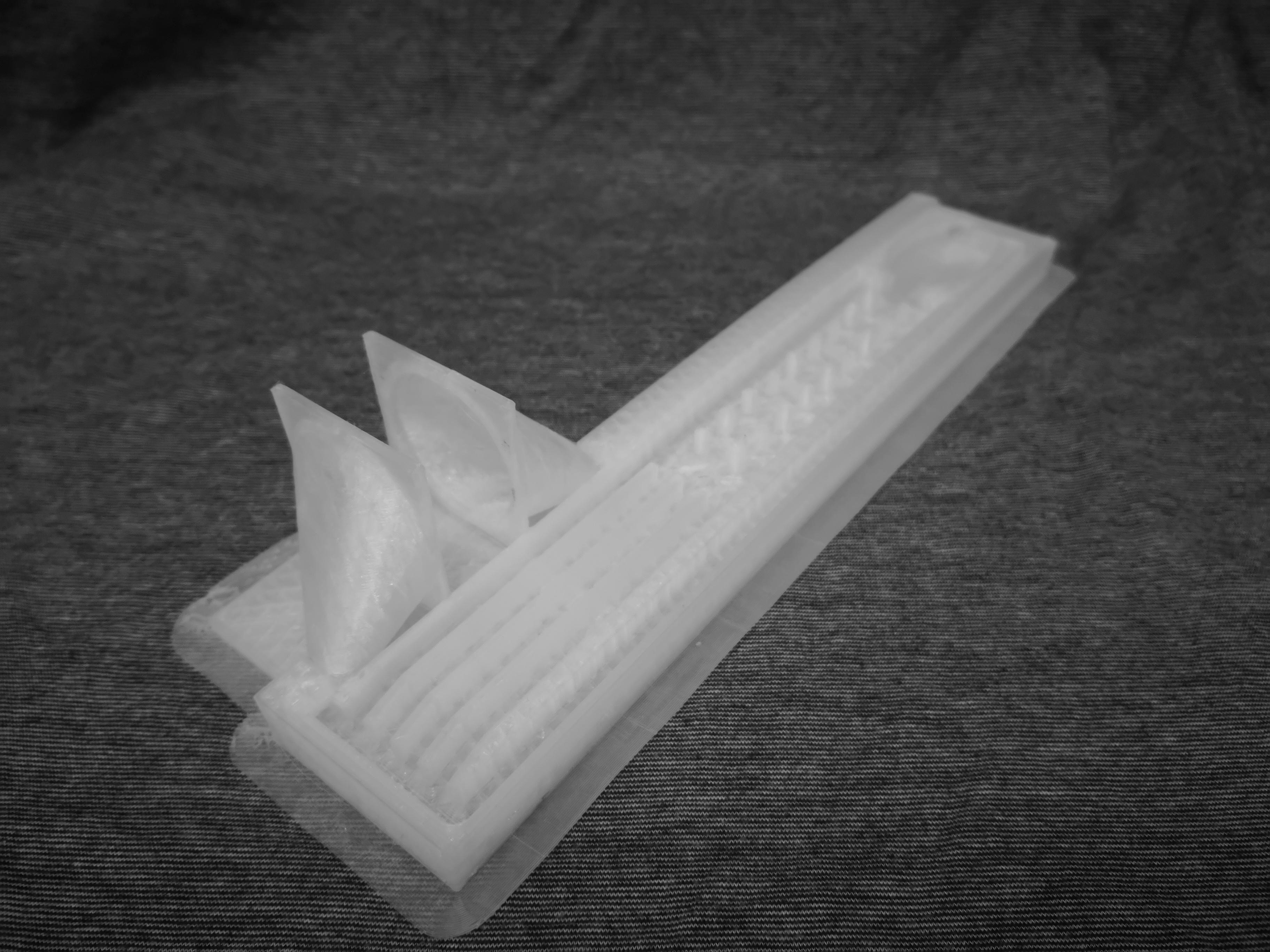
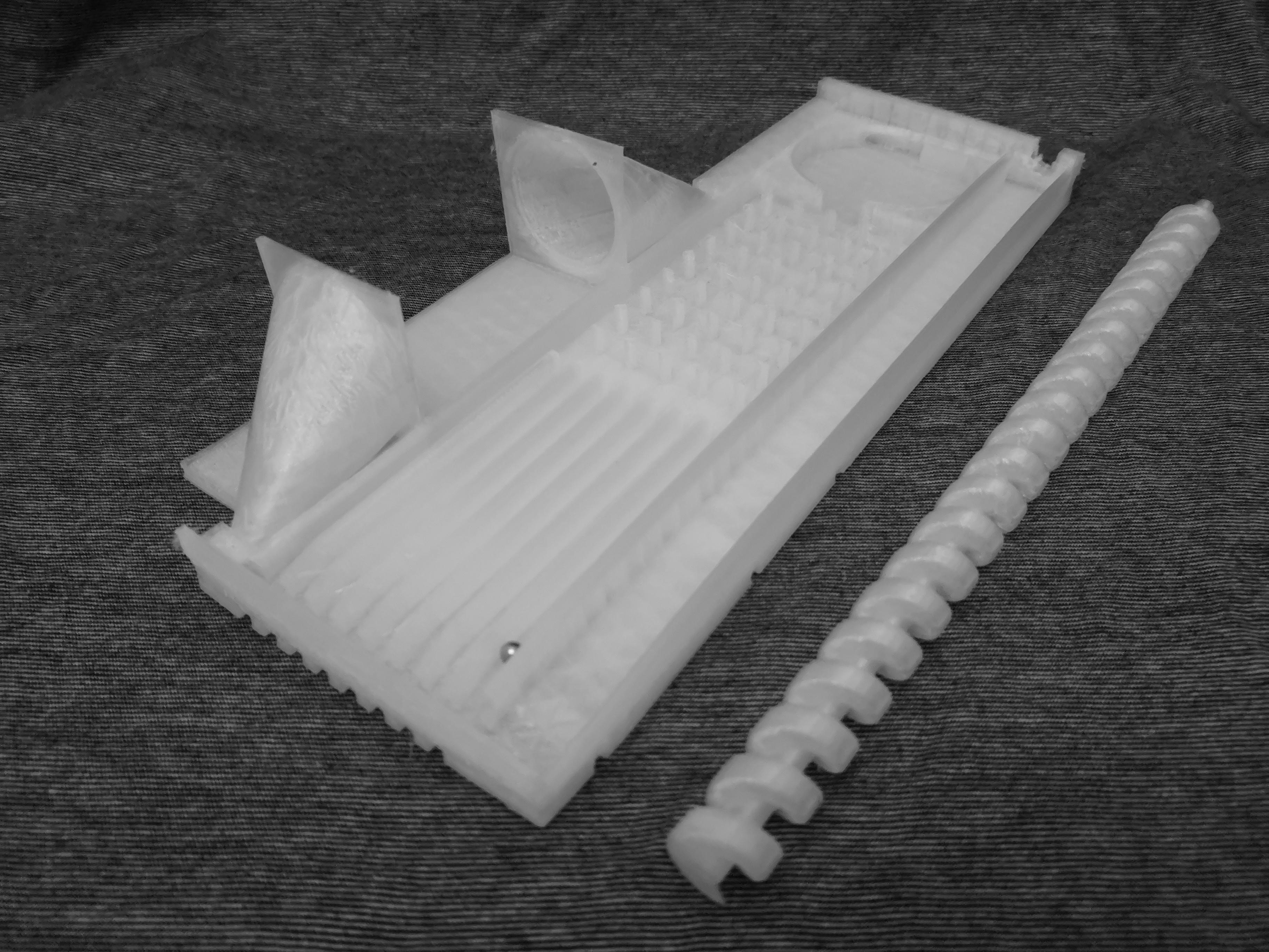
For version 3.0 the spiral has to be cut out from the supporting cylinder. While the spiral can be printed with out the supporting cylinder, it will result in a more difficult to print and keep a high tolerance for the moving mechanics.
![]()
![]()
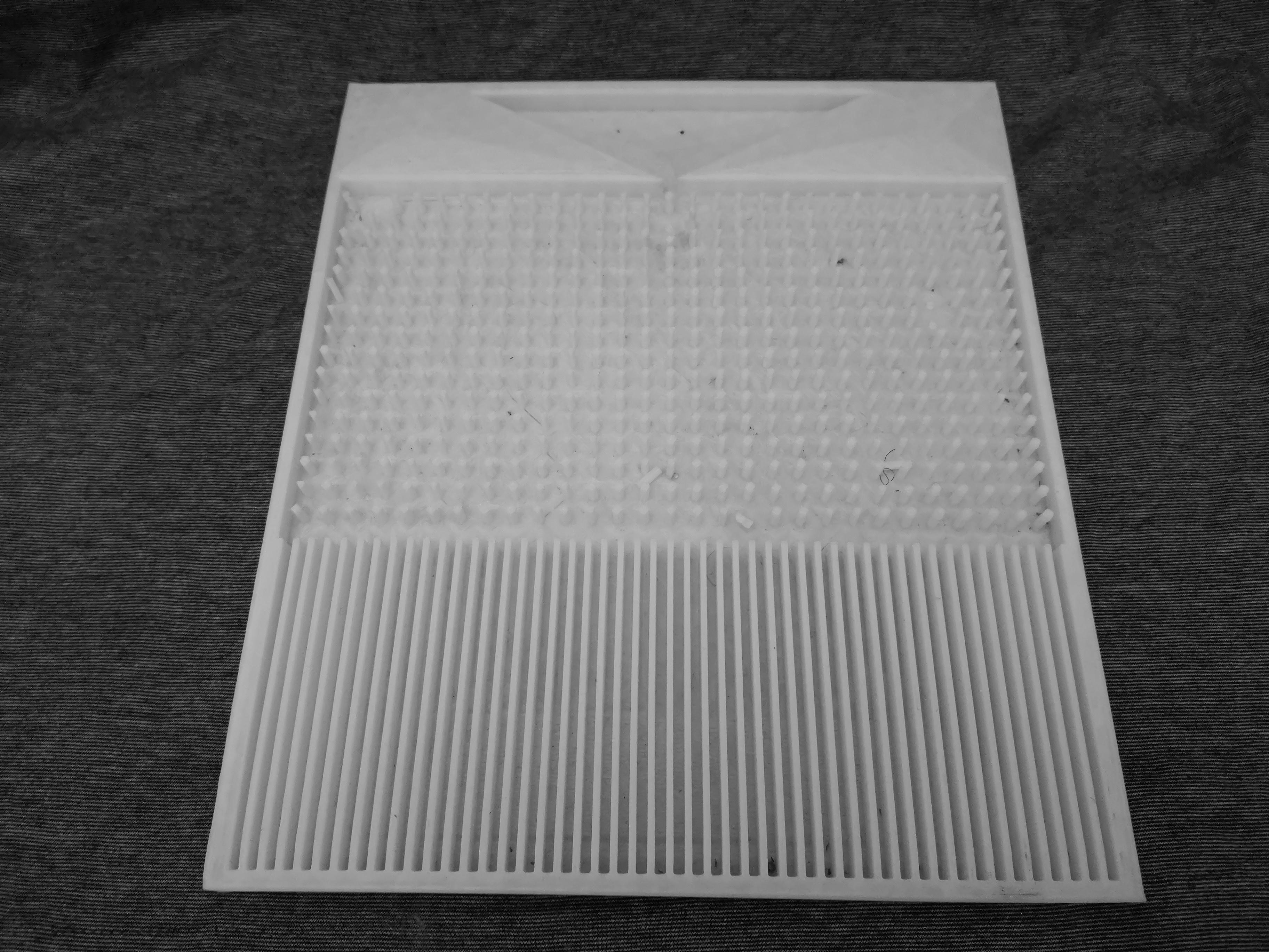
printed board version_1.0 ![]()
printed board version_2.0 ![]()
-
3Electrical wiring
Once this is done the electrical wiring can be done, by interesting the pins head of the jumper cables the intended holes of each of the bins. When the bearing balls pass pins head, they close the electrical circuit and result in an analog high signal. It is recommend to add 10K ohm resistors to the ground wiring of each of bins, to privet signal static.
![]()
The rest of the wiring can the be done by follow the graphic bellow:
![]()
-
4Setting up the arduino
To set up the arduino the IDE has to be downloaded and installed from the official arduino website.
Open the arduino sketch in the repository with the IDE, compile and upload the code.
At the current state the code only support for reading from the multiplexer, and writing on the serial port. Further versions of the could can control the spiral motor and fan speed.
The well-tempered chaos sequencer
A mechanical chaos musical instrument based on the intuitive visual relationships between musical structures and generic chaos


Discussions
Become a Hackaday.io Member
Create an account to leave a comment. Already have an account? Log In.