-
Don’t Panic! This is probably improvised music!
10/21/2018 at 19:37 • 0 commentsMusical improvisations can be as virtues as any musical compositions. It take many years of playing and training to mastering the moment with a musical expression. But there is probably an easier way!
![]()
SOURCE: WIKI
In The Video below the well tempered chaos sequencer is used to improvise music. Each of the sensor in the bins is mapped to note a musical scale or cord, the rest is done bay the falling bearing balls.
![]()
-
Don't Panic! This is probably not the end!
10/21/2018 at 04:12 • 0 commentsWhile it was fun as it lasted, there is probably enough time, thinking and energy invested in this project so far! while this might be the end for a while this is probably not the end! The joy of this project can from the endless probables where the sequencer can be used. While the basic goal behind working on this project on this web site was to create the basic parametric geometry with as simple a electrical and mechanical probably as possible, the whole scope of this project is about expend the ideas started here and going bananas.
![]()
This last log entire is about listing untouched ideas are left either for later or the imagination:
- OpenCV: Using computer vision and camera will open up the idea of chaos in this baord.
- Music from every day objects: exchanging the pin with objects of the every day life will also result in interesting musical ideas
- Mechanical Computation: while designing the board the idea of using this board as a mechanical computer has always very near.... i wounder where this will go.
- Music Theory: looking forward to playing around with music Theories like the progression from rhythm to melody or trying some probabilistic rhythm
- can this be used for a tool for fluid turbulence simulation? probably!
thank you
this was fun!
wish every one a pleat meal!!! and good food!
-
Don't Panic! This is probably a good sensor!
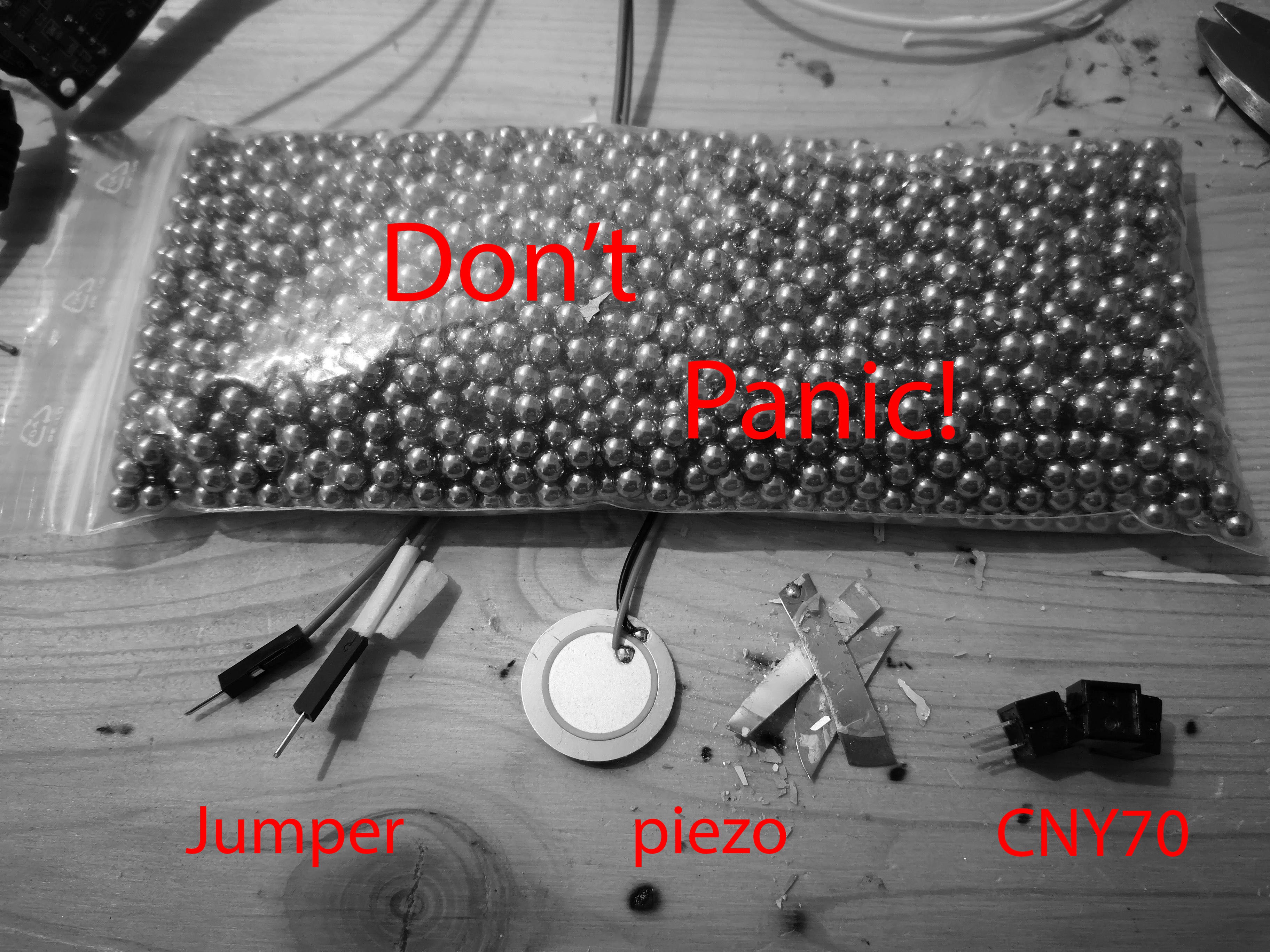
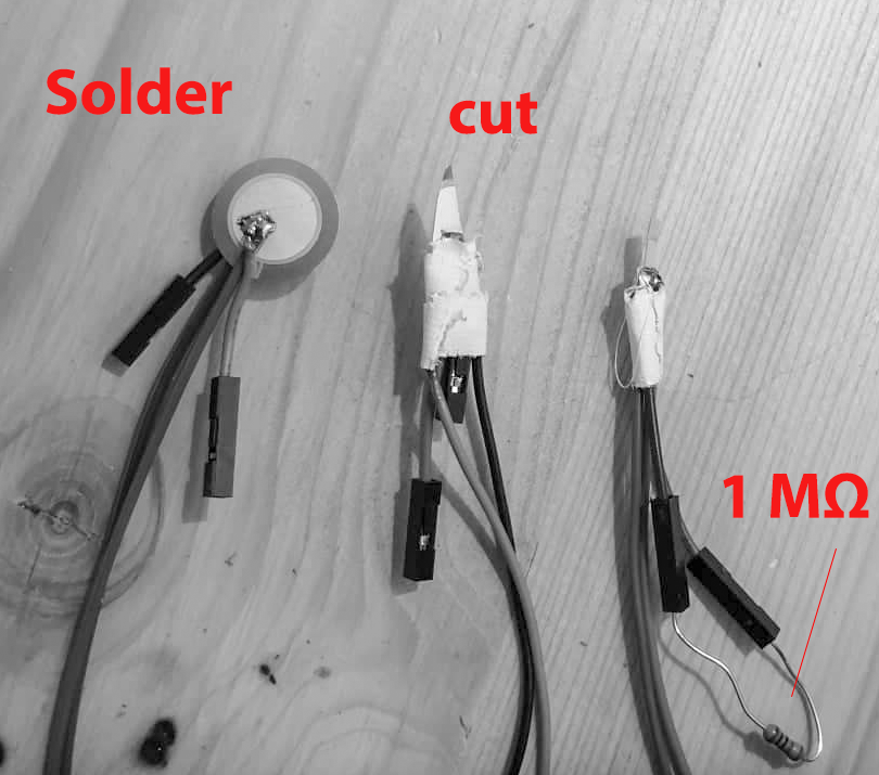
10/21/2018 at 02:57 • 0 commentsWhile the best sensor is the probably the one you don't have, there is number of sensors that are probably just as good! For this project the sensor for counting the bearing ball fall in a bin of a board had to be a simple and cheap as possible. This is especially import for make the board simple to build and easily reproducible. At the current stage of the project three kind of sensors were take in to consideration:
- No Sensor - just jumper cable.
- CNY70 : Reflective Optical Sensor with Transistor Output.
- Piezo elements - or at least s small part of one.
![]()
Those three Sensor where used in developing the board. Each sensor had its advantages and problems. most interestingly was the fact that each of sensor had its one probably of functioning!
Sensor price code soldering build
difficultyprobably of
workingNo Sensor less 0.20€ analogRead() no very low low CNY70 2.00€ analogRead() yes high mid Piezo 0.40€ analogRead() yes mid high ---------- more ----------# no sensor - just jumper cable
Using no sensor was one of the main concepts for his project. The idea was to embed jumper cables in the 3D-printed model to act as button, switches or electrical electrical circle. This had the advantage that probably no soldering would be needed and the hole electrical circuit would be built within minutes.
![]()
The jumper cables pina each connected to the Arduino:
5V --> Jumper cable pin 0
Analog in XX --> Jumper cable pin 1
In this case the bearing balls when touching both jumper will close the electrical circuit. The resulting analog signal by the Arduino analog read would have clear spikes that are very definitive for registering a falling bearing ball.
![]()
THE DOWN SIDE of this sensor is it's tolerance as the probably for this sensor to register a falling ball is very low. Most of the times a bearing ball would touch only one pin or even jump over both pins. if the pins of the jumper cable were to be pushed deeper in to the board this would result in to blocking the bin.
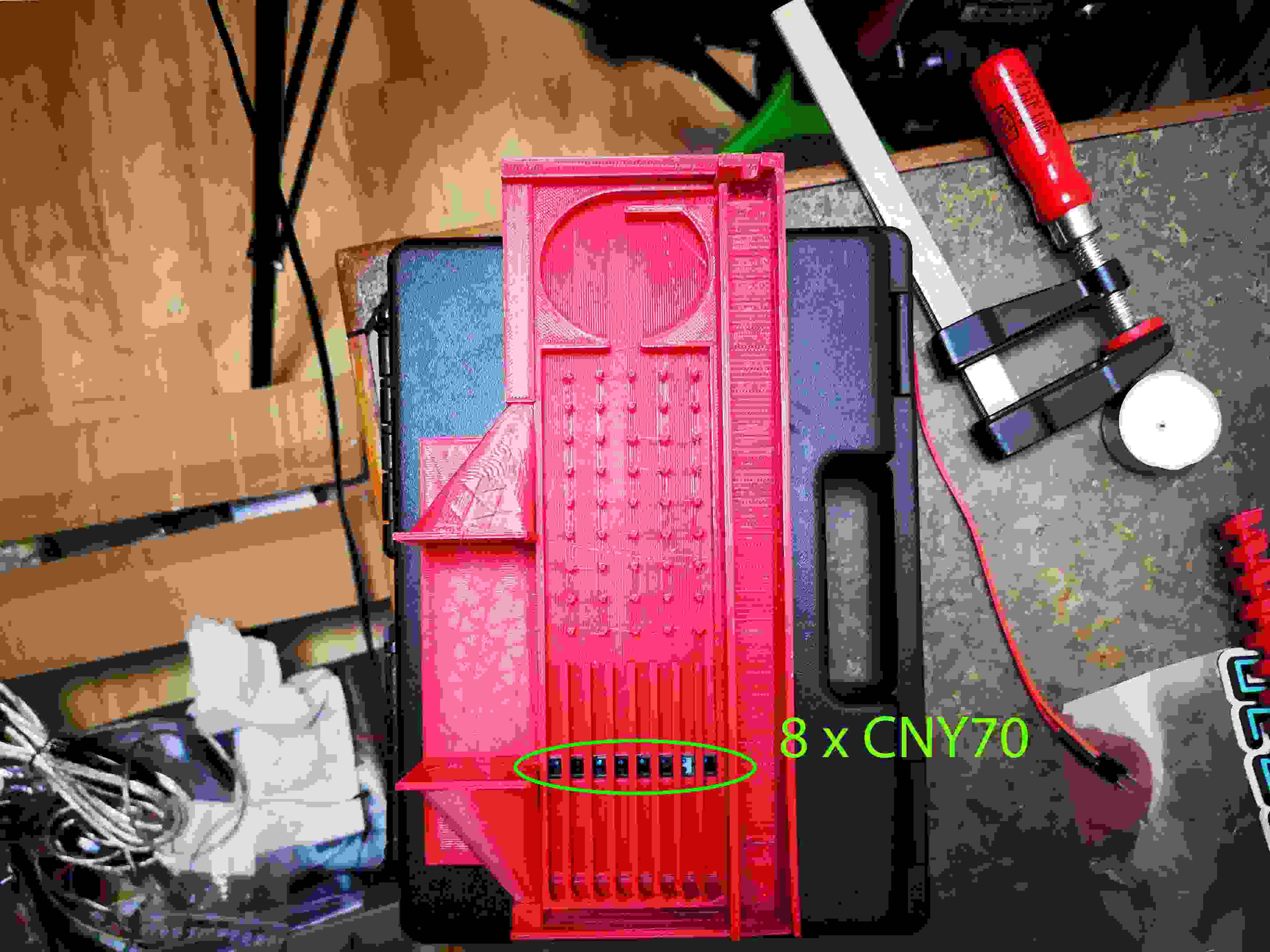
# CNY70 : Reflective Optical Sensor with Transistor Output
This is probably the most expensive sensor used in this project ( around 2€ each). The sensor is very accurate and reliable.
![]()
SOURCE: https://www.tme.eu
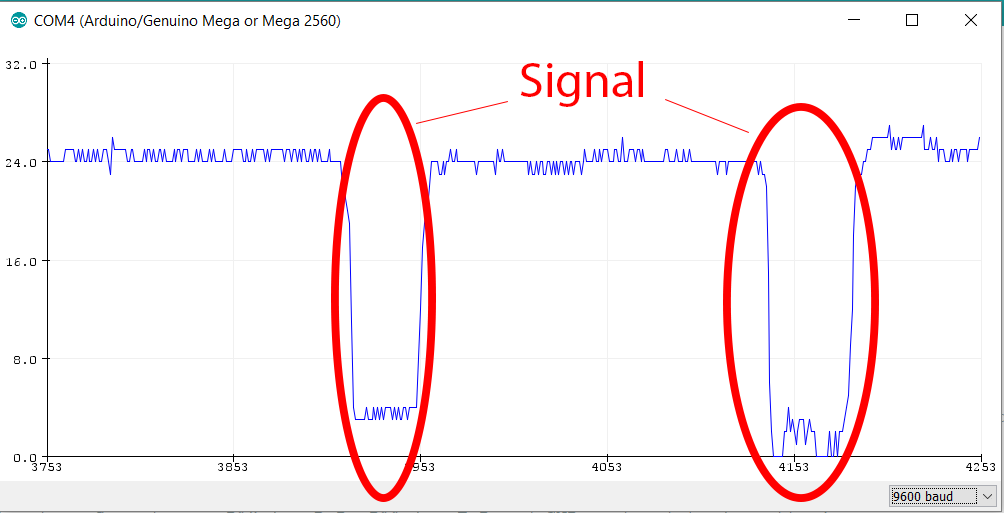
The sensor uses an infrared emitter and phototransistor. A falling bearing ball will act as a refactor for emitted infrared light and the phototransistor will register the falling ball. Reading the sensor using the Analog in of the Arduino gives even an indication of the proximity of the a bearing ball to the phototransistor, by the fraction of the ball that reflects to back to sensor.
![]()
THE DOWN SIDE of this sensor is its high price and complexity. For this sensor to work properly the bearing ball should fall within a fixed distance from the sensors. Ball falling closer than this fixed distance or even touching the sensor will probably not be detected as they will not reflect the the infrared light back to phototransistor.
![]()
# Piezo elements - or at least s small part of one
Piezo elements are probably the most beautiful sensor of all time and universe. They simple, cheap and very reliable. Even if they are too big to fit in one of the bis can be easily fixed by cutting out a strip of the element.
![]()
SOURCE: https://www.arduino.cc/en/Tutorial/Knock
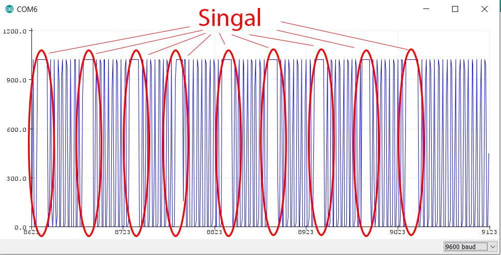
When the bearing ball hits piezo element it will result in clear peek. This can be seen in the reading from the Arduino analog in. This signal is perfect as it very short can be easily translated to musical events using simple thresh holding.
![]()
THE DOWN SIDE of this sensor is that it has to acoustically isolated for each bin. The isolation is very important so that the sensor only registers the bearing ball fall in that specific bin. The isolation of the sensors is done using plastic or foam. Another done side is that sensors tend to break when cutting them. Cutting works but one has to be very careful.
![]()
-
Don't Panic! This probably has MIDI!
10/21/2018 at 02:44 • 0 comments1MIDI, being MIDI, has gotten to the inside of every electron musical instrument. while very simple it has still made it as the common language of a generation of musical instruments. This log shows how a cheap MIDI USB hub is used to translate the boards language to MIDI.
![]()
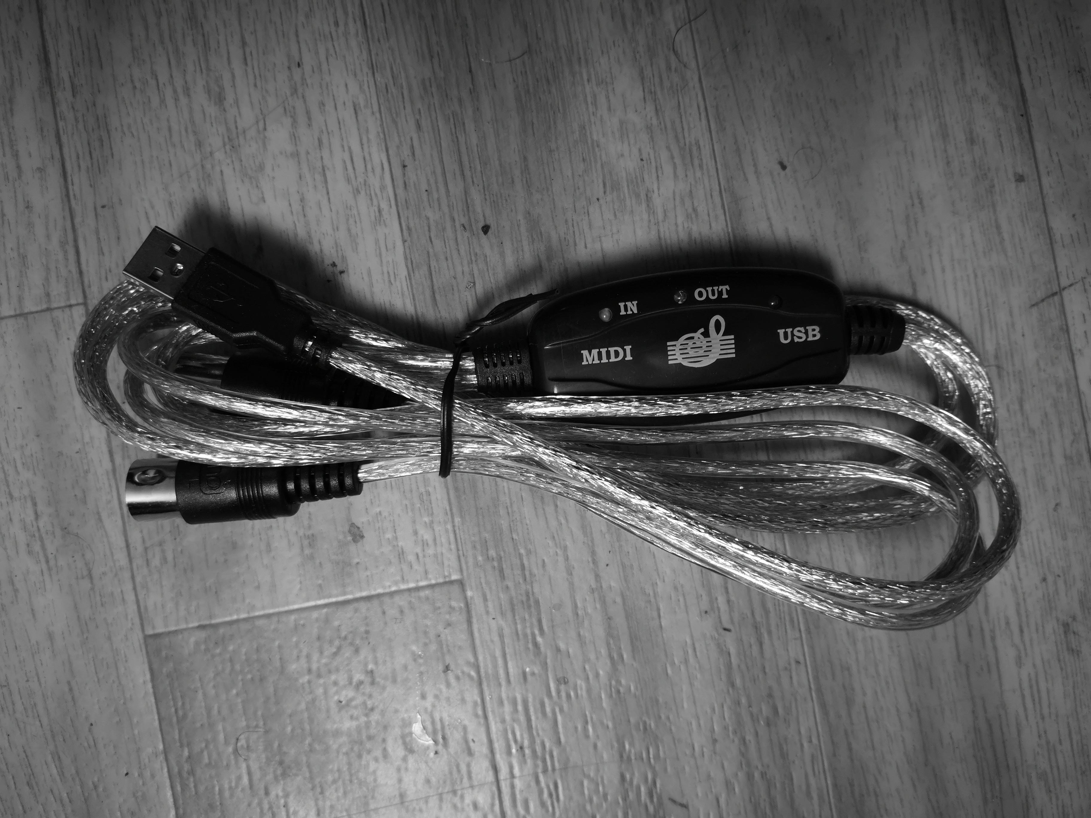
A cheap MIDI to USB hub can be used to create both a MIDI out and USB-MIDI interface.
![]()
![]()
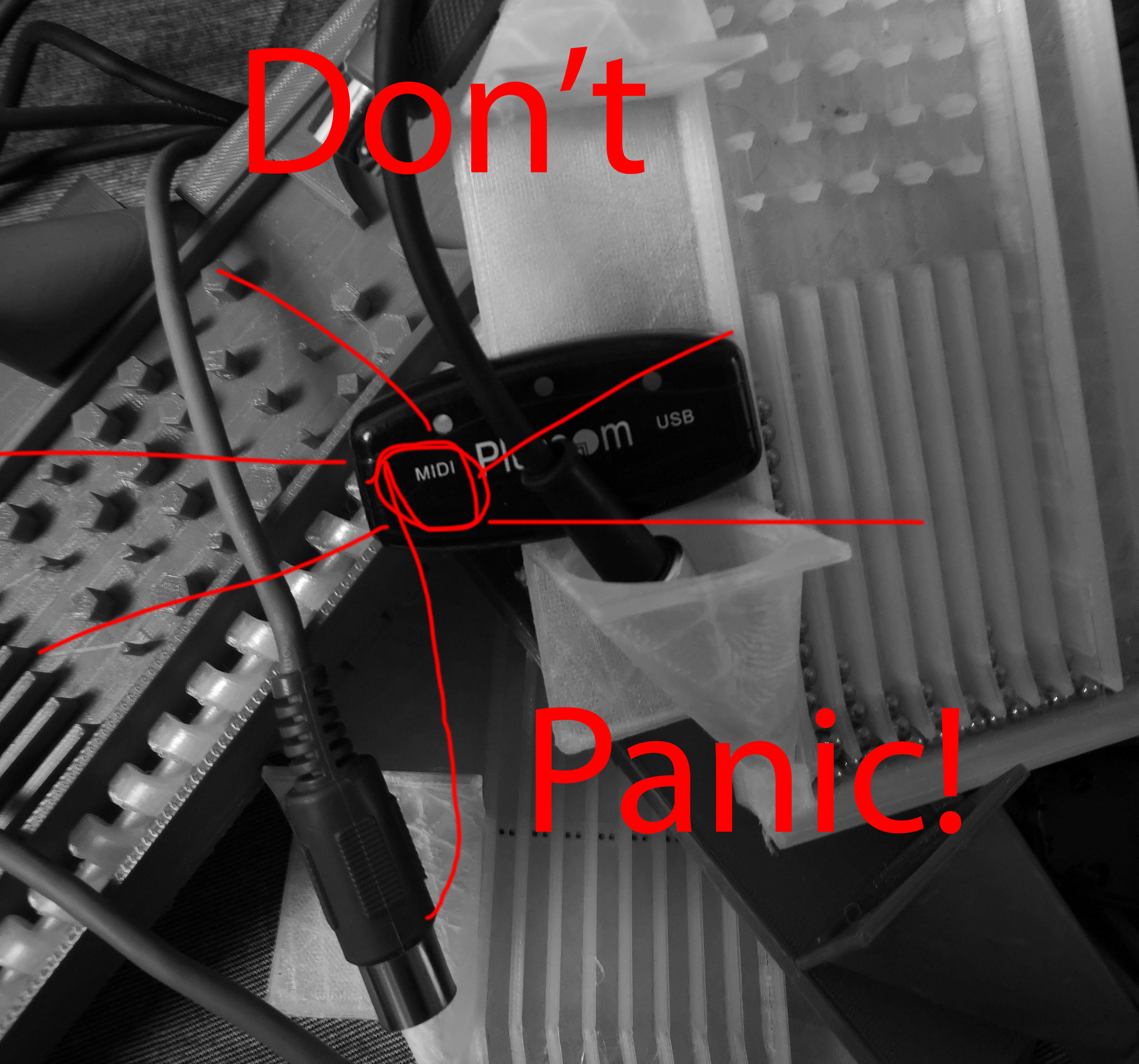
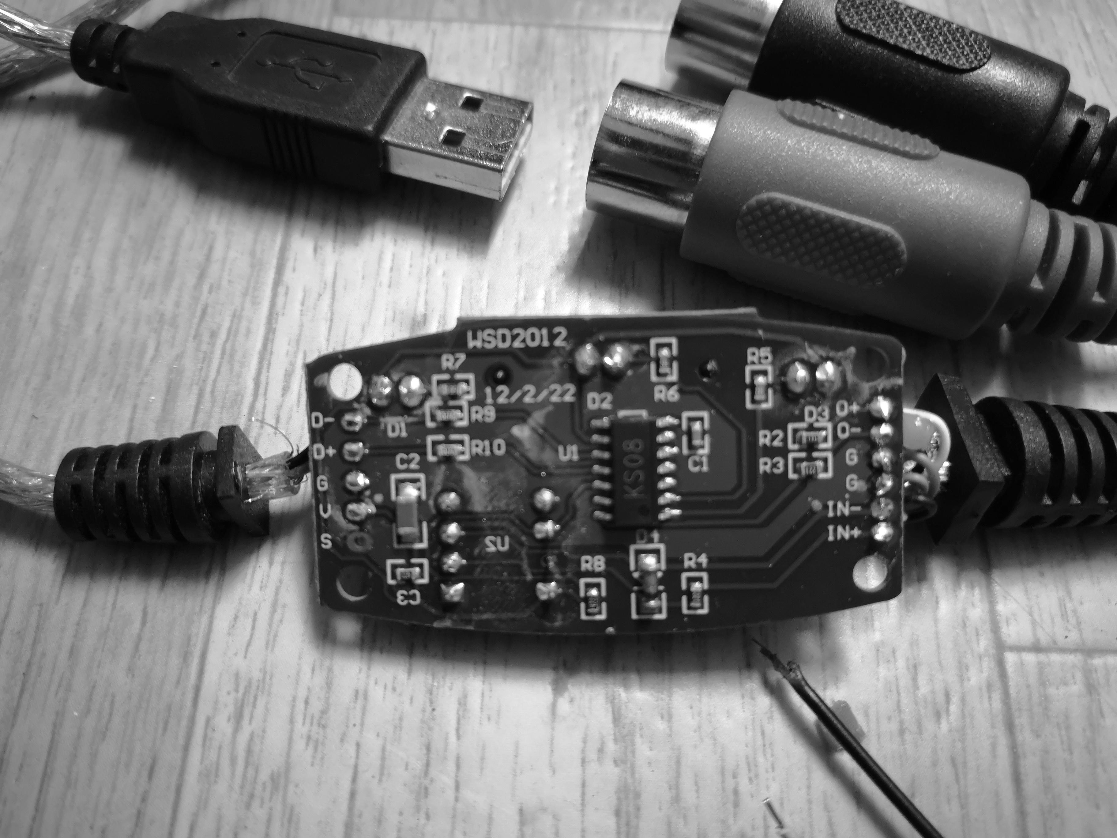
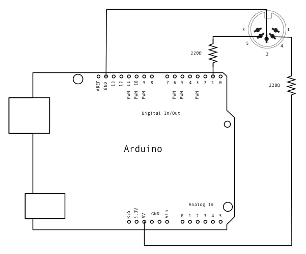
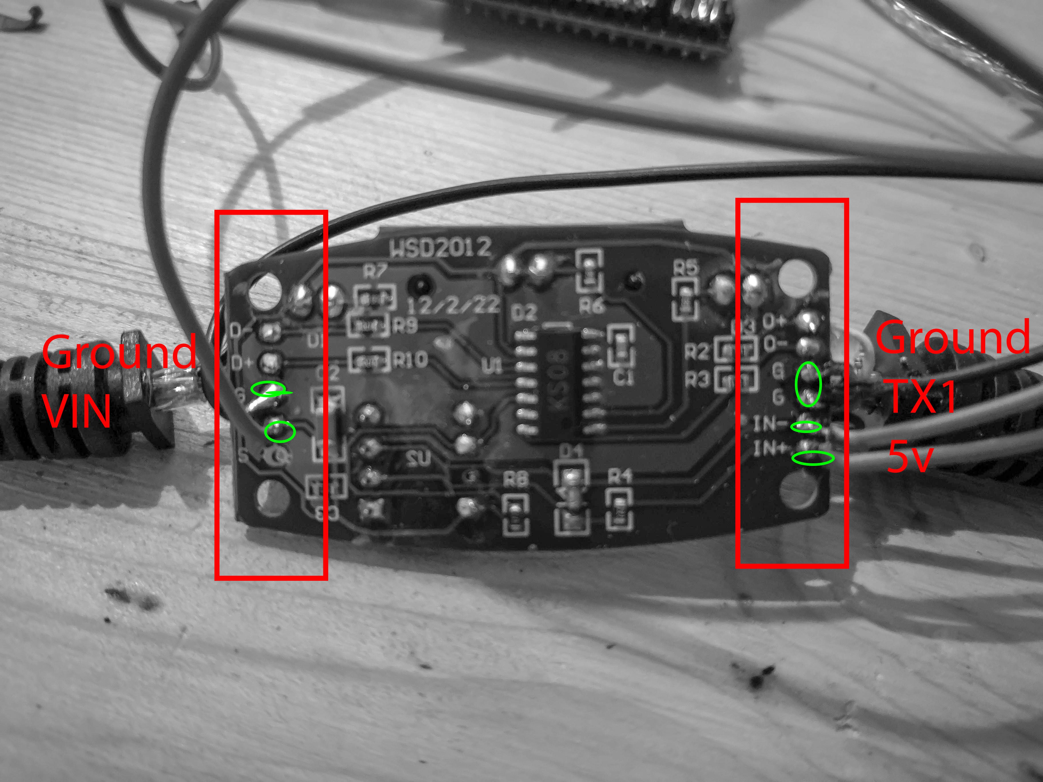
To build a MIDI interface simple open the MIDI hub and connect the following cables using a jumper stander jumper cables:
![]()
SOURCE: https://www.arduino.cc/
The wiring should be like this:
Ground hub --> Ground Arduino
IN- --> TX1 Arduino
IN+ --> 5V Arduino
!!! IMPORTANT !!! : The MIDI hub SHOULD also be used to power the Arduino. Using the MIDI hub as power supply will give the best result for the communication between the hub and the Arduino as they will share the a common ground voltage. The Arduino is in this case also connected to USB power source to the MIDI-HUB:
Ground USB --> Ground MIDI hub --> Ground Arduino
5V USB --> 5V MIDI hub --> 5V Arduino
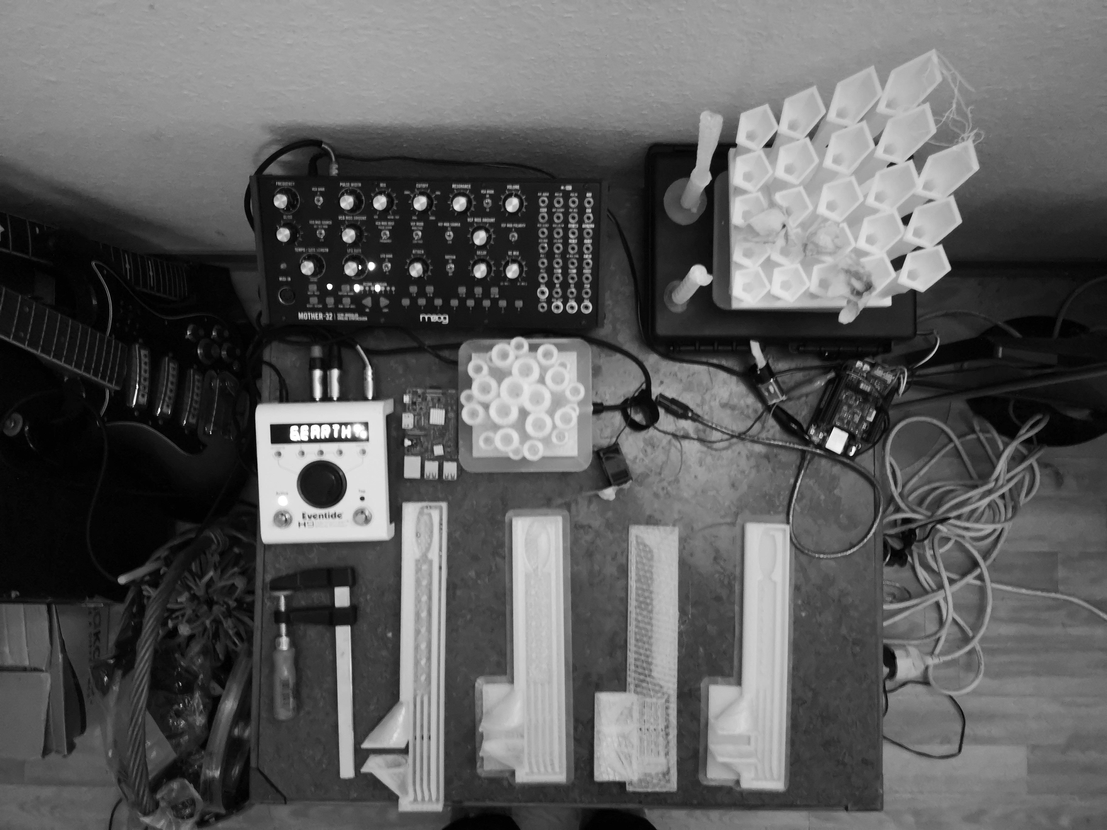
When done the hole thing should look like this:
![]()
On the Ardunio side one should install the MIDI library either using the library manager of the IDE or from the Git repository. After this is done MIDI messages can be sent from Arduino using the following functions:
     // Send note on 42 with velocity 127 on channel 1
     MIDI.sendNoteOn(42, 127, 1);

     // wait for 500 ms
      delay(500);

     // Send note off 42 with velocity 127 on channel 1
     MIDI.sendNoteOff(42, 127, 1);
For more example and the code that is used for the board see the repository for this project.
-
Don’t Panic! This is probably a good approximation!
10/15/2018 at 13:36 • 0 commentsIt might be seem improbable to be able to calculate the probability of where the bearing balls will fall. Don’t Panic! every thing has an open source solution!
![]()
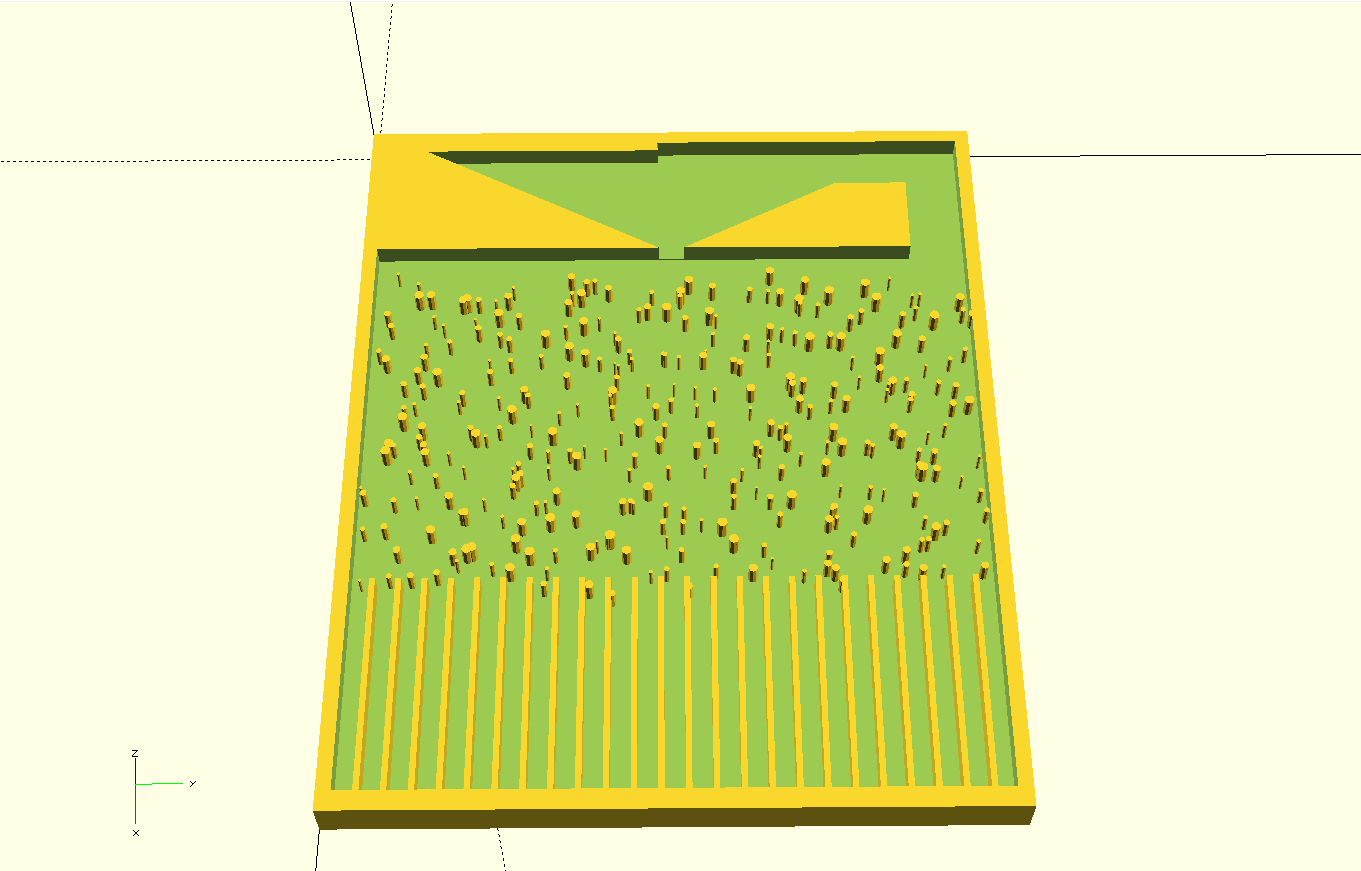
Yet under the assumes that the probability function of the ball distribution is a function of the Geometry of the pins and the radius of the bearing balls, it would be possible to calculate this probability for simple symmetrical shapes and certain ball radius to pin size proportion.
![]()
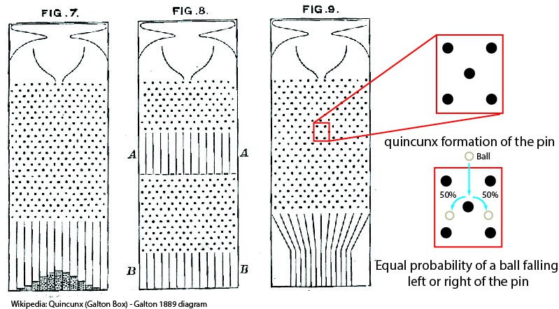
It’s by this logic that it is possible to calculate that for circle symmetrical pins in a quincunx formation, as probability for bounding to right of left of the pins becomes unbiased or equally probably. This will result in a binomial distribution of the bearing ball in the pins; explanation.
For random geometry this because much more default very quickly. Calculating the path of a ball for an biased fall probability is almost improbable. To still be able to estimate this probability numerical summation can be used to give a good approximation.
![]()
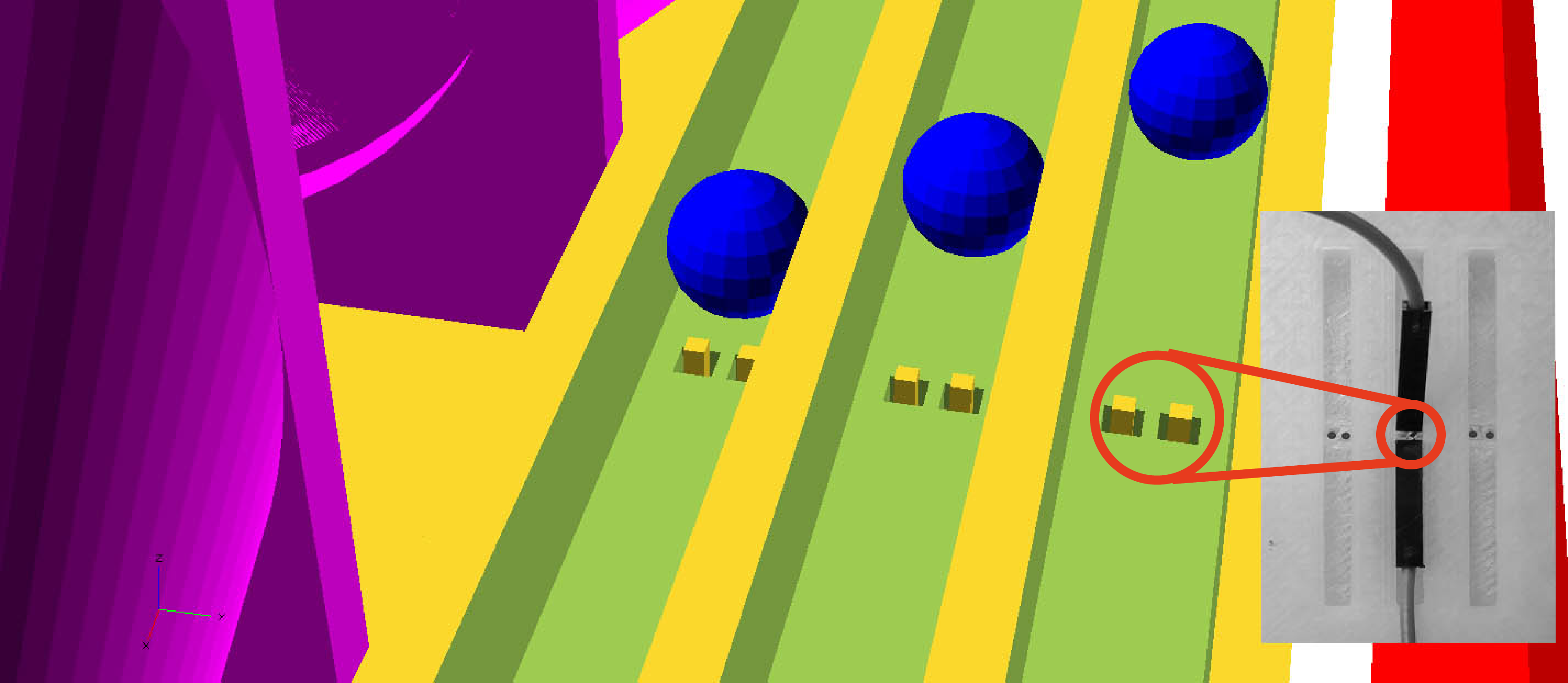
The simulation shows how bearing balls will fall in the bins, can be approximated using a simulation model of water falling from the top board over the bins of geometry. The simulation should be consider under the two considerations:
- As the water mas can be seen as an infinite number of infinite balls. The infinite number of balls insure that simulation will converge to the resulting probability
- As the bearing balls are of finite size, the quality of this approximation will depend of the proportion of the radius of the balls to the characteristic length of the spacing between geometry. The characteristic length being a function or to simplify an average of the value of the spaces between the pins.
For a larger spacing between the geometries, the balls will behave more like a fluid and the simulation results match the bearing ball distribution. With this in mind the simulation becomes a helpful to test the results.
Things will get more interesting for more complex geometry:
# Running The Simulation
The simulation uses the InterFoam Solver for two incompressible, isothermal immiscible fluids using volume of fluid phase-fraction based interface capturing approach, with optional mesh motion and mesh topology changes including adaptive re-meshing, see Wiki for more information about the solver. The Simulation uses RANS-Based turbulence modeling.
The simulation can be easily reproduced using the open source library OpenFOAM (Open Source Field Operation and Manipulation). It possible to run the simulation on linuxbe simply installing OpenFOAM or on windows or mac by installing Docker.
![]()
After OpenFOAM or Docker has been installed download the simulation configuration files for the repository. The simulation folder has also includes OpenSCAD file that should be used to generate the STL of the board of the board. The generated geometry should be named
```bash
board.stl
```
and placed within the folder
```bash
/contant/triSurface
```
For basic used the simulation is only configured to ran with this OpenSCAD file and using the same bounding geometry for the board. The simulation’s results will be valid only for variations of the pins on the board or any geometry based in place of the bins. For other board geometries the simulation code would still be valid by the configuration files should be adjusted.
To run the simulation can be stated by navigating using PowerShell(windows) or Terminal to the simulation folder and running the command:
for Linux, Windows or Mac first run:
```bash
docker run --rm -it -v ${PWD}:/home/openfoam openfoam/openfoam6-paraview54 /bin/bash
```
then run the command to start the simulation :
```bash
./Allrun
```
!!! Attention: The simulation will take about 6-12 hours depending on the used hardware and the will use about 5 GigaBytes of Hard disk memory!!!
To view the results open the file using paraview.:
```bash
results.OpenFOAM
```
-
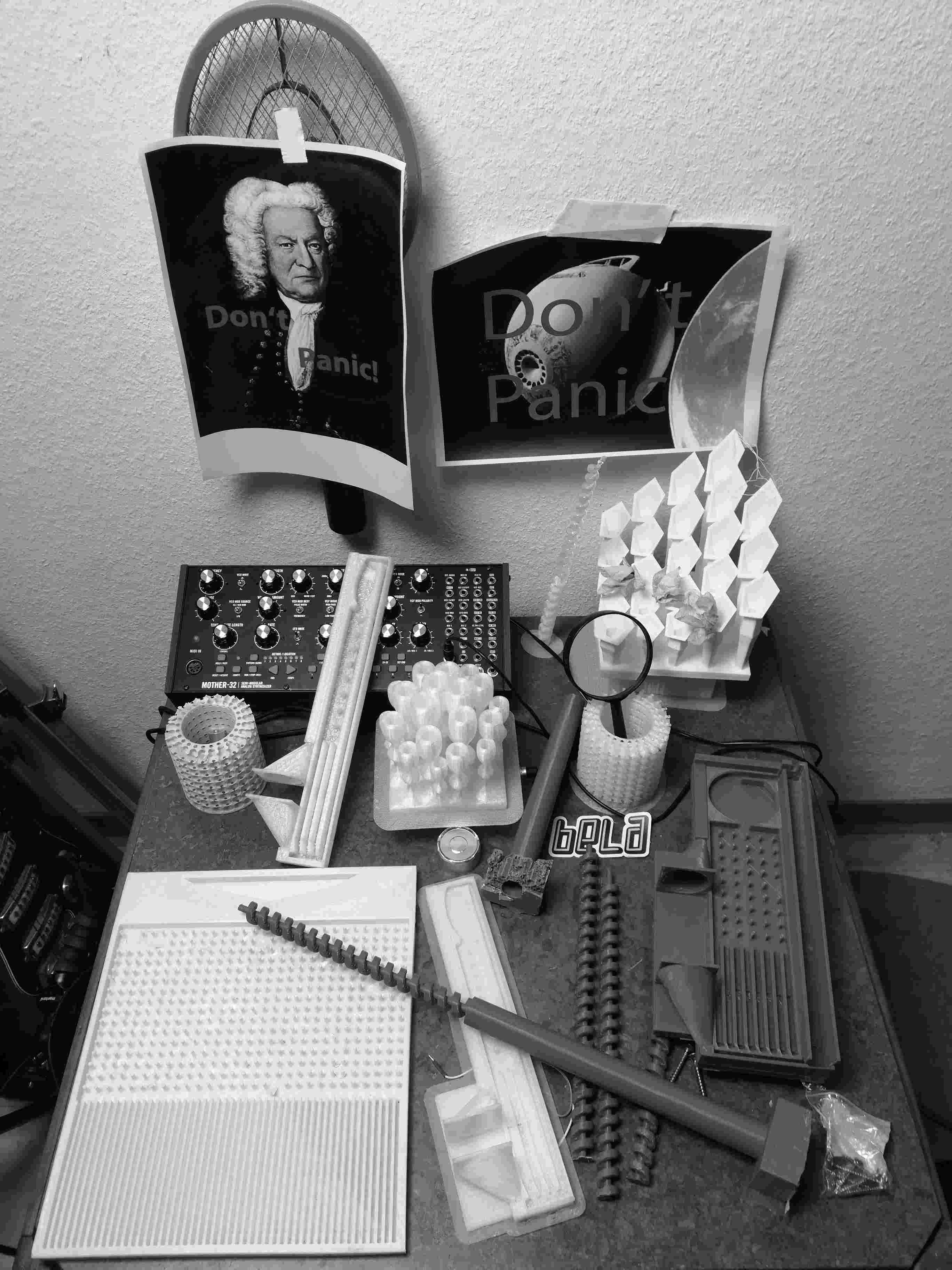
Don't panic! It's probably going to work!
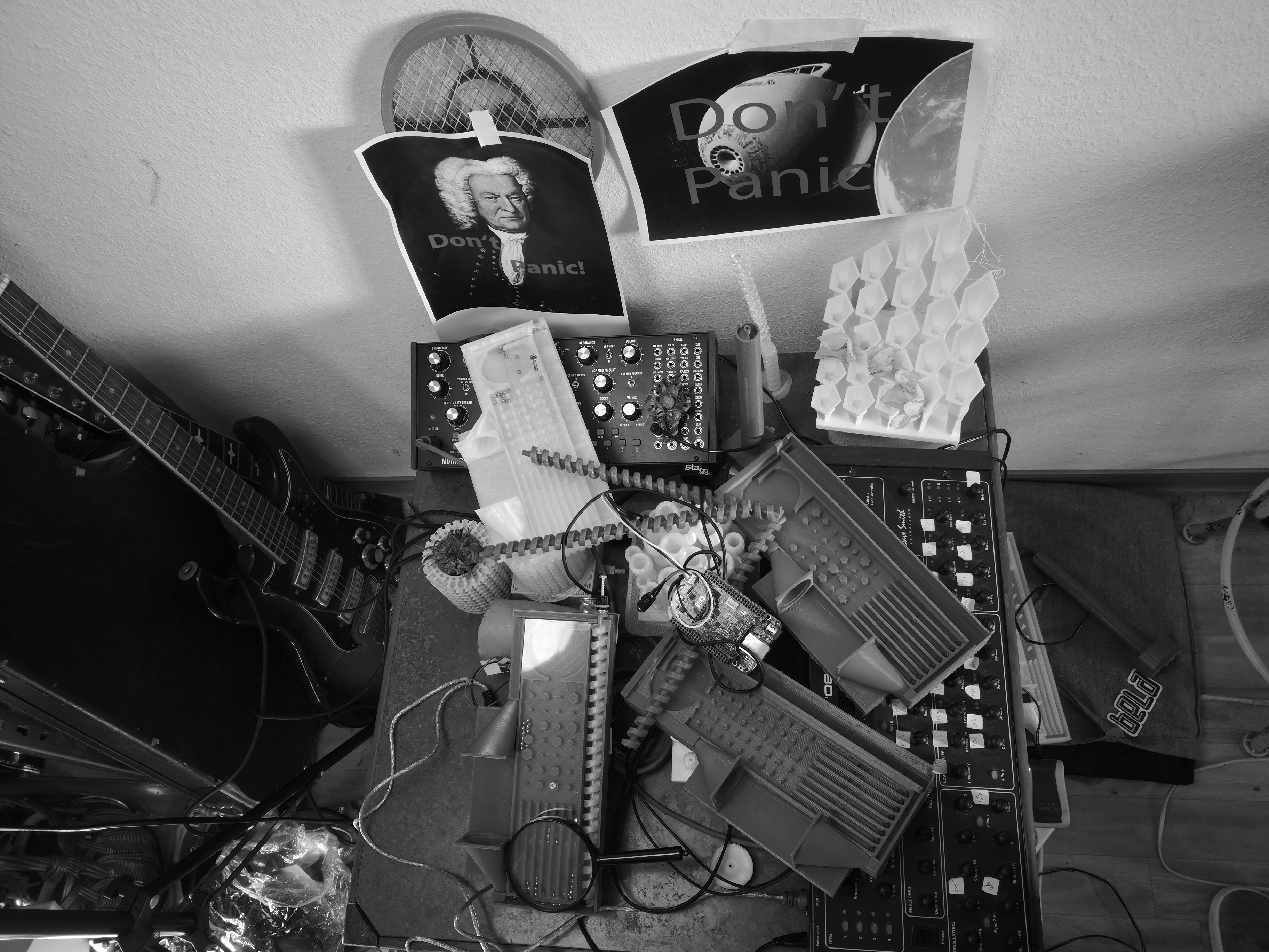
10/08/2018 at 20:30 • 0 commentsMaking simple design is not simple. The number of interfaces between the different systems decreases the over all tolerance of the system. Specially the fact that the 3D-print should include embedded electrical components and buttons adds a probably to each parameter of the design, that something will not work. Considering the number of tries and failed prints make the system play a tone feel like flying the Heart of Gold space ship with its Infinite Improbability Drive. Don't panic! It's probably going to work!
![]()
Heart of Gold: The Hitchhiker's Guide to the Galaxy ![]()
the video below shows how the system might probably work! Only one bin of all the failed an successful prints is used as CV-trigger input for the Moog Mother-32 semi-modular analog synthesizer. The synthesizer is connected to Eventide H9 reverb and has a LFO modulating the filter. It is probable that if a bearing ball falls in the right bin, the synthesizer is triggered.
!!! There is something wrong with the webpage link is working but video is not shown!!!
mrrrx/review/294022611/525f125e17
-
The boards
10/05/2018 at 00:55 • 0 commentsDon't panic! They are all probably useful!
![]()
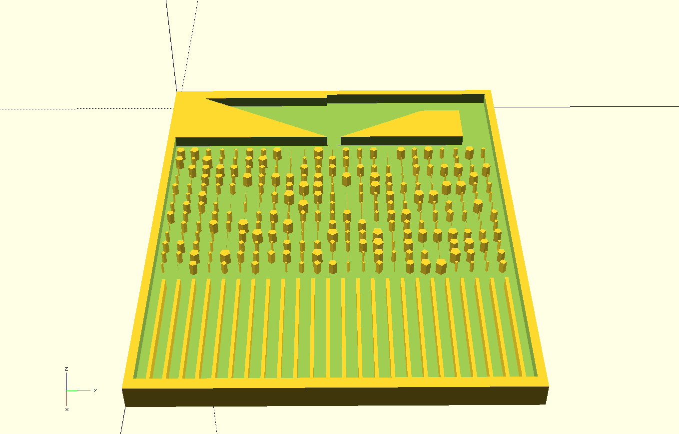
At the current state of developing the board there are 4 versions on github repository. Each of these versions is based on a different configuration of the board's peripherals. All of the versions are valid.
The evolution of each version can be see using the following steps:
-version 1: simple Board with no mechanics or electronics
-version 2: added fan funnels and tubing for automatic return of the bearing balls using air pressure
-version 3: added mechanical driven spiral to propagate the bearing balls
-version 4: add the slops for moving the bearing balls better.All versions will be consolidated in a single parametric model, once the rest of the electronics and mechanics are fully developed.
-
Geometrical Functions
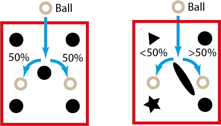
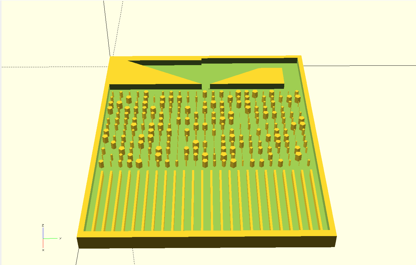
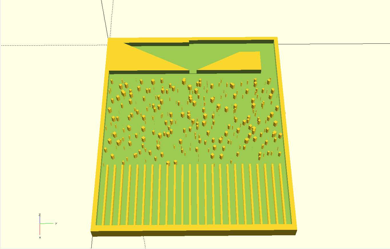
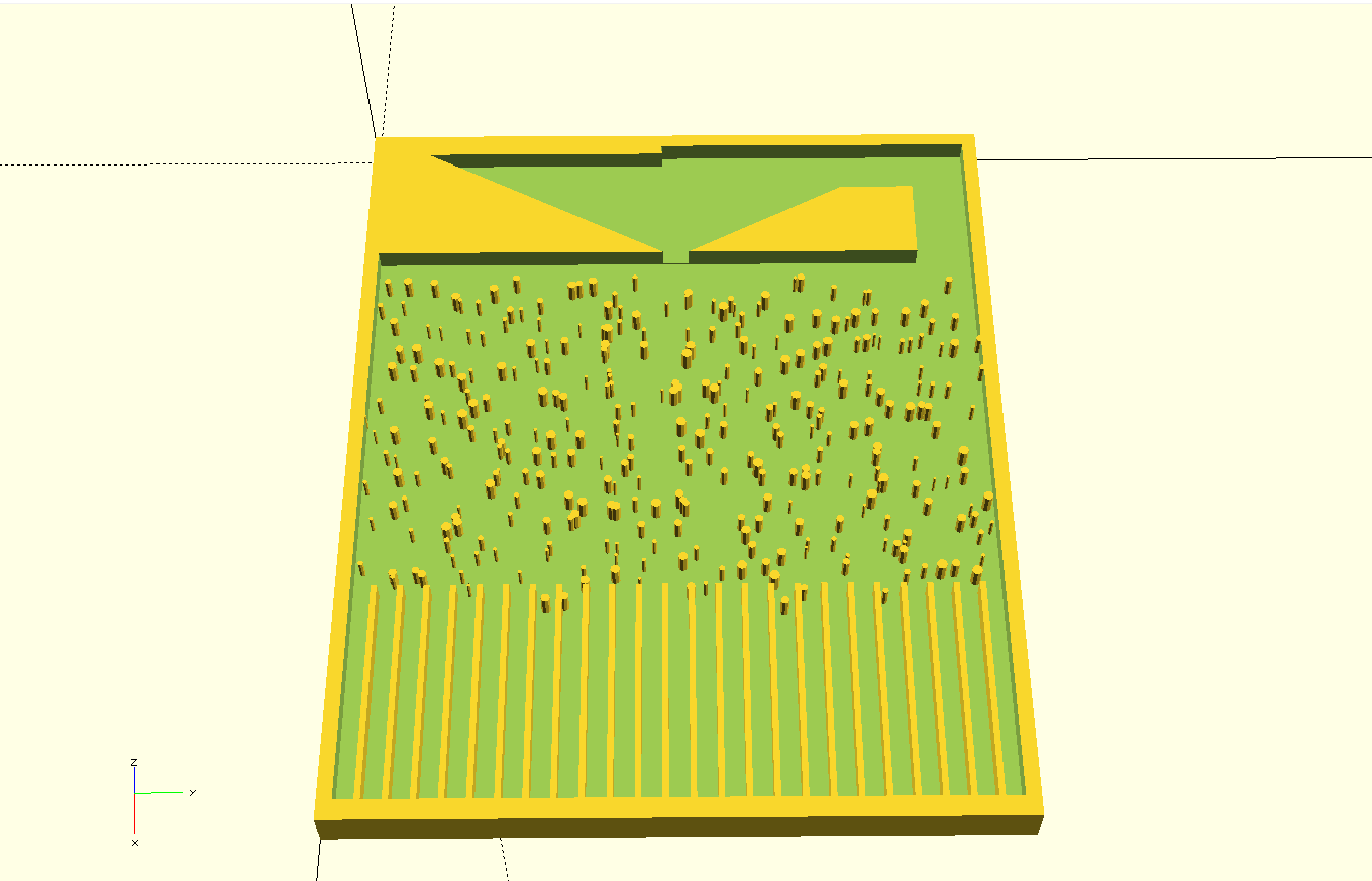
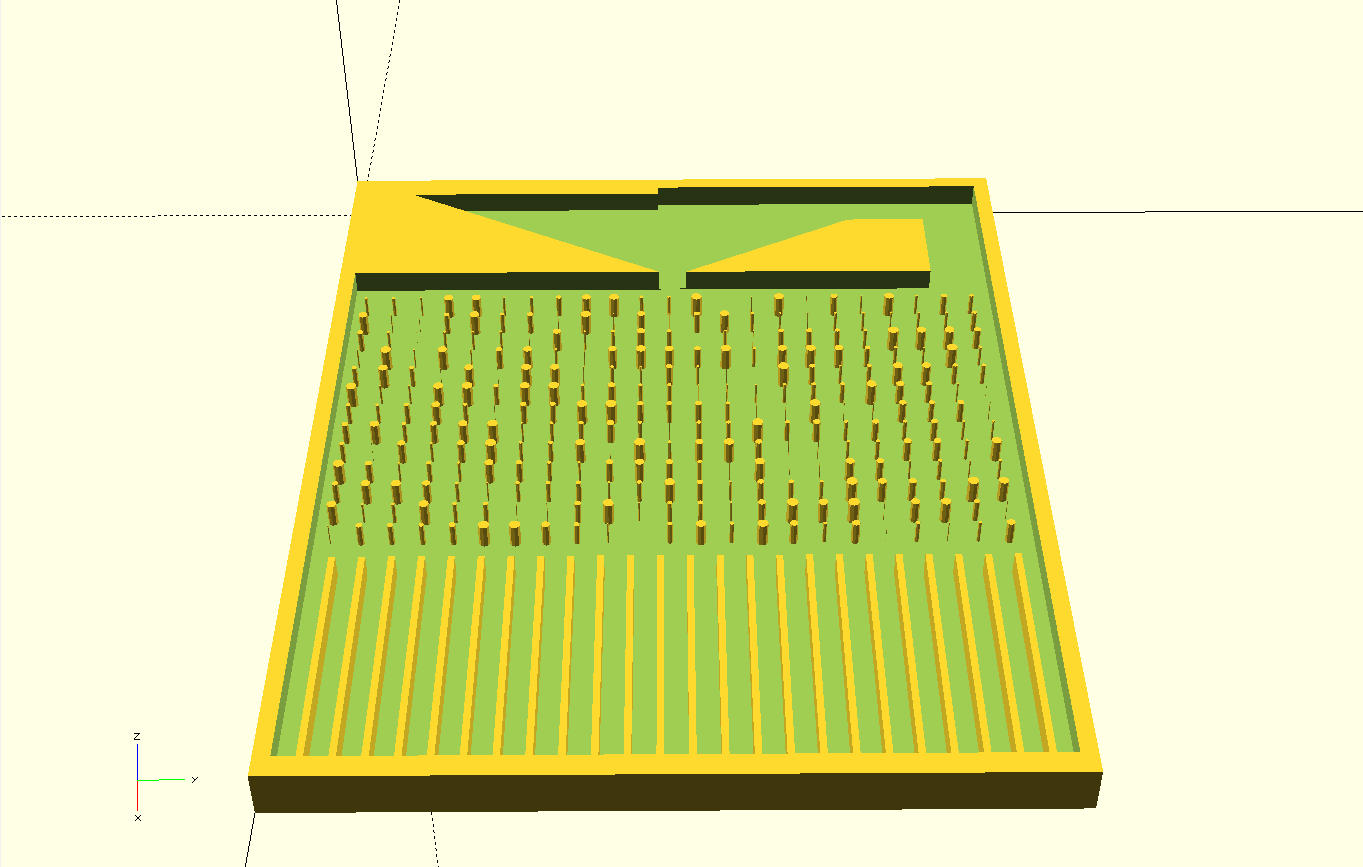
10/05/2018 at 00:41 • 0 commentsThe probability of where the bearing ball fall is a function of the shape of the object in the path of the bearing balls. For symmetrical shapes the probability bearing ball falling is identical for both the right and left side.
![]()
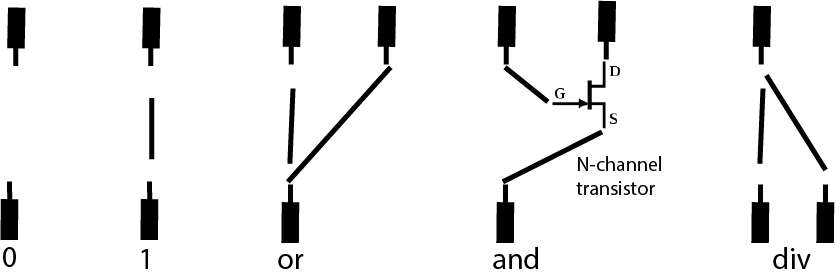
Further more the binary logic of the sequencer can be expanded using the bread board logic.
![]()
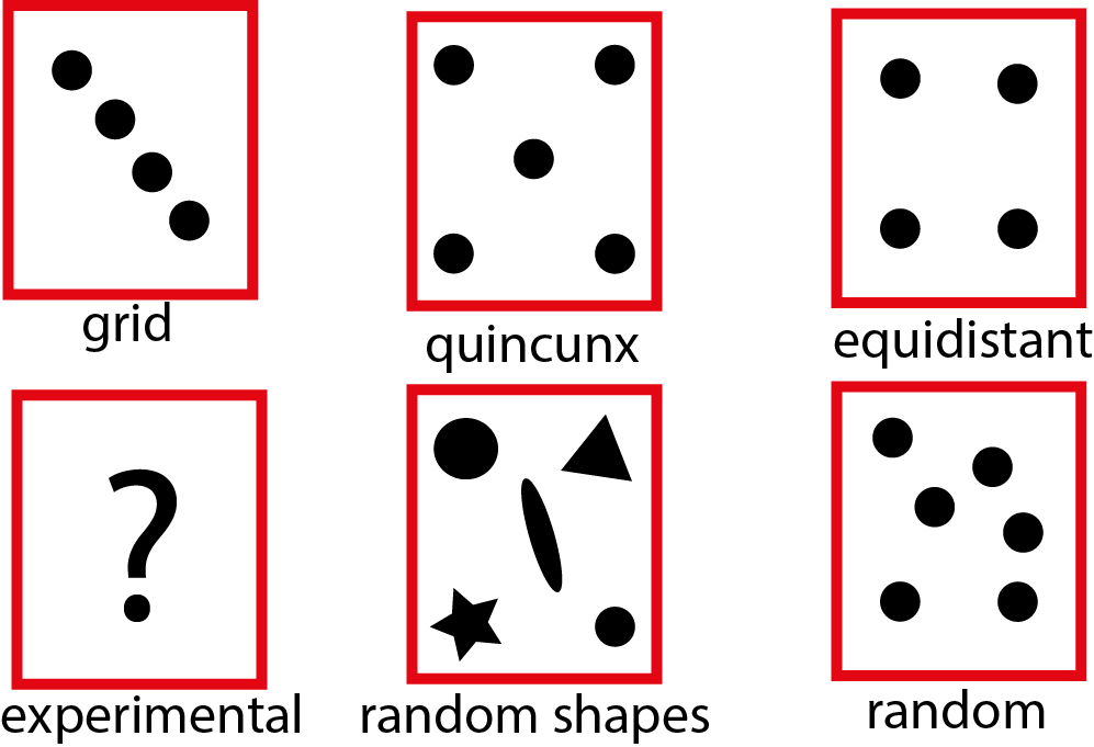
The geometrical logic can be used to create different function spaces that can be tests using the sequencer. The script of the board can be easily modified to generate different geometrical functions.
![]()
Examples:
![]()
![]()
![]()
![]()
![]()
![]()
-
how is the chaos sequencer tool-kit a musical instrument?
10/04/2018 at 23:30 • 0 commentsWhile in principle anything that can produce sound could be considered a musical sound device, a musical instrument stands out by the ability to reduce a complex physical system of sound generation to obey the temperaments of a musician. Much like a piano, an organ, a guitar or a synthesizer the instrument rewrites the underlying physical system to an intuitive language. This language that is set by the instrument creates the unique emotion by which it is distinguishable.
Another fact that distinguishes a “great” instrument is probably best stated by the Bushnell's Law: “all the best games are easy to learn and difficult to master”.
Taking these two facts into account while conceiving what could be a musical instrument, it is possible to hypothesize how the instrument and its language should be learned, played and mastered.
One can imagine that for a person holding the instrument for the first time, the basic level of the instrument’s language should allow to easily find the notes on the schema of the instrument. Much like how the notes are laid on the piano keys or different frets and grips on a guitar there is basically not a lot more that is needed to learn or even maybe master the instrument. For the most part of this musical journey a minimal amount of physics is even only implicitly needed.
Yet on the other end of this musical journey lies a very complex physical system that produces these tones and frequencies. Concepts of acoustic systems of any instrument such as the proportion of length and notes, frequency to a resonant body, all the way to the dynamics of exciting a string to a note, only become evident with progression of musical talent.
Therefore what makes a musical instrument a unique object is the transcendental relationship between the complexities of physics and simple intuition of the senses.
Much as the notion of realizing lengths and proportions of strings by listening for their frequencies, through language of tones to lengths the well-tempered chaos sequencer sets to illustrate notions of chaos by the virtue of the underlying emerging structures through a high number of repetitions and an intuitive visual aid.
![]()
-
Inspiration
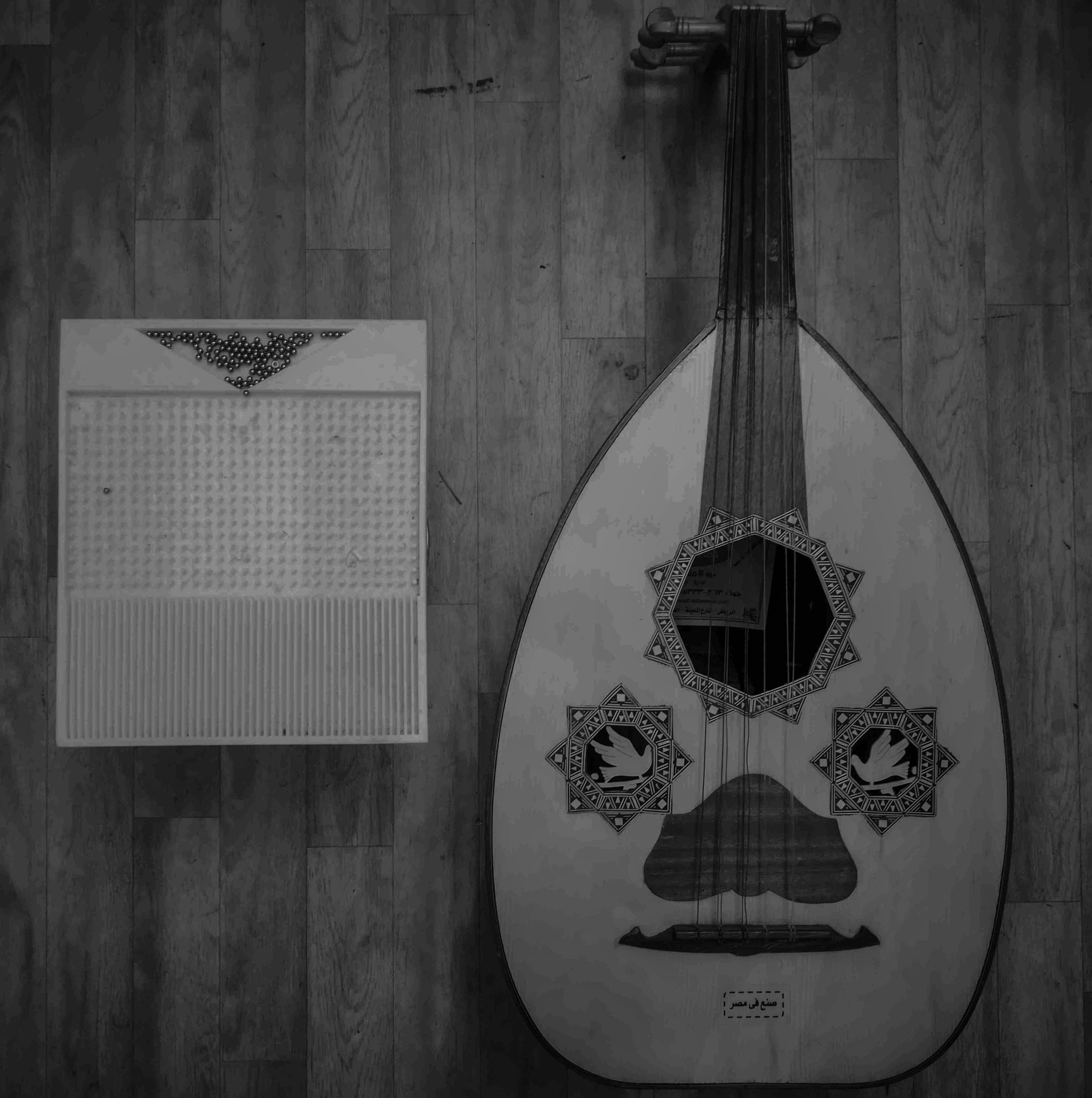
10/04/2018 at 22:48 • 0 commentsThe tool-kit is based on the Galton board, which was invented by Sir Francis Galton (1822-1911) to illustrate the central limit theorem, which is a key concept in probability theory. The board consist of pins that are arranged in a quincunx pattern, that stand in the path of falling bearing balls. As ball bearings negotiate their way between the pins and arrange to a number of bins at the bottom of the board, they generate a high number of independent random events, that by intuition would result in random distribution of the balls in the bins.
![]()
Yet for a large enough number of bearing balls and large number of bins the heights of accumulated balls in the bins will always approximate a normal distribution (informally known as a "bell curve"). The board shows that for large number of recurrences the underlying structure of chaos system can be adequately approximated.
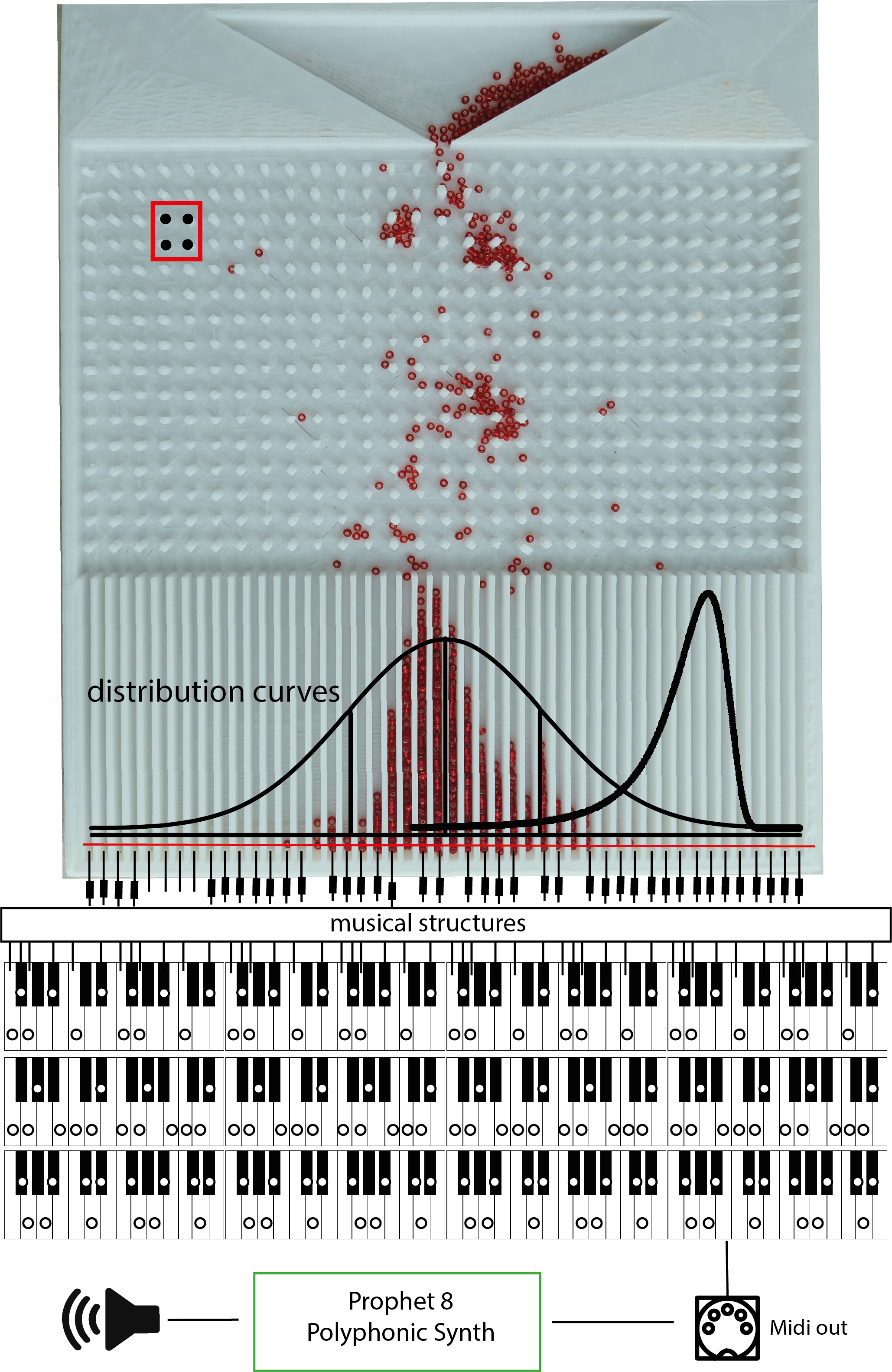
The well-tempered chaos sequencer
A mechanical chaos musical instrument based on the intuitive visual relationships between musical structures and generic chaos