jaromir.sukuba
-
Misc.
10/07/2018 at 19:52 • 0 commentsDuring testing of the instrument, I found a few things to improve:
1, I used Kanthal wire for strings. This wire is great for wire-wound resistors (that's why I had a lot of the wire in my workshop), but it is a bit tarnished on the surface, causing both unclear intonation of the instrument and stained fingers of the player. I ordered nichrome wire, should be better for this task.
2, The fingerboard is too wide. I need to make it thinner and possibly curved.
3, The curvature of sensor head is not enough and occasional unwanted neighboring string is bowed. A tiny bit more of curvature should do the trick.
4, Playing with sound. While not completely bad, it can be improved. I thought of adding a few coupled resonance filters after mixer (uhm, schematics will make it clear) to make the sound more live.
5, I setup the magnetic sensors (sensing bow speed) according to my non-cellist style. Real cellists are playing with more energy, so the instrument is lacking rather huge part of dynamic range. Playing with resistors in voltage control mixer should do the job.
6, MIDI output? Should be doable.
7, I need to see real cello one day. Really, I never held this instrument in my hands. From this perspective, decision to start making cello may sound a tiny bit silly. Let's call it exploring new horizons instead.
-
How it works together
10/06/2018 at 21:27 • 0 commentsFor now I described how four control blocks work (VCO, VCA, VCF) and how sensors work, now it's time to put it together.
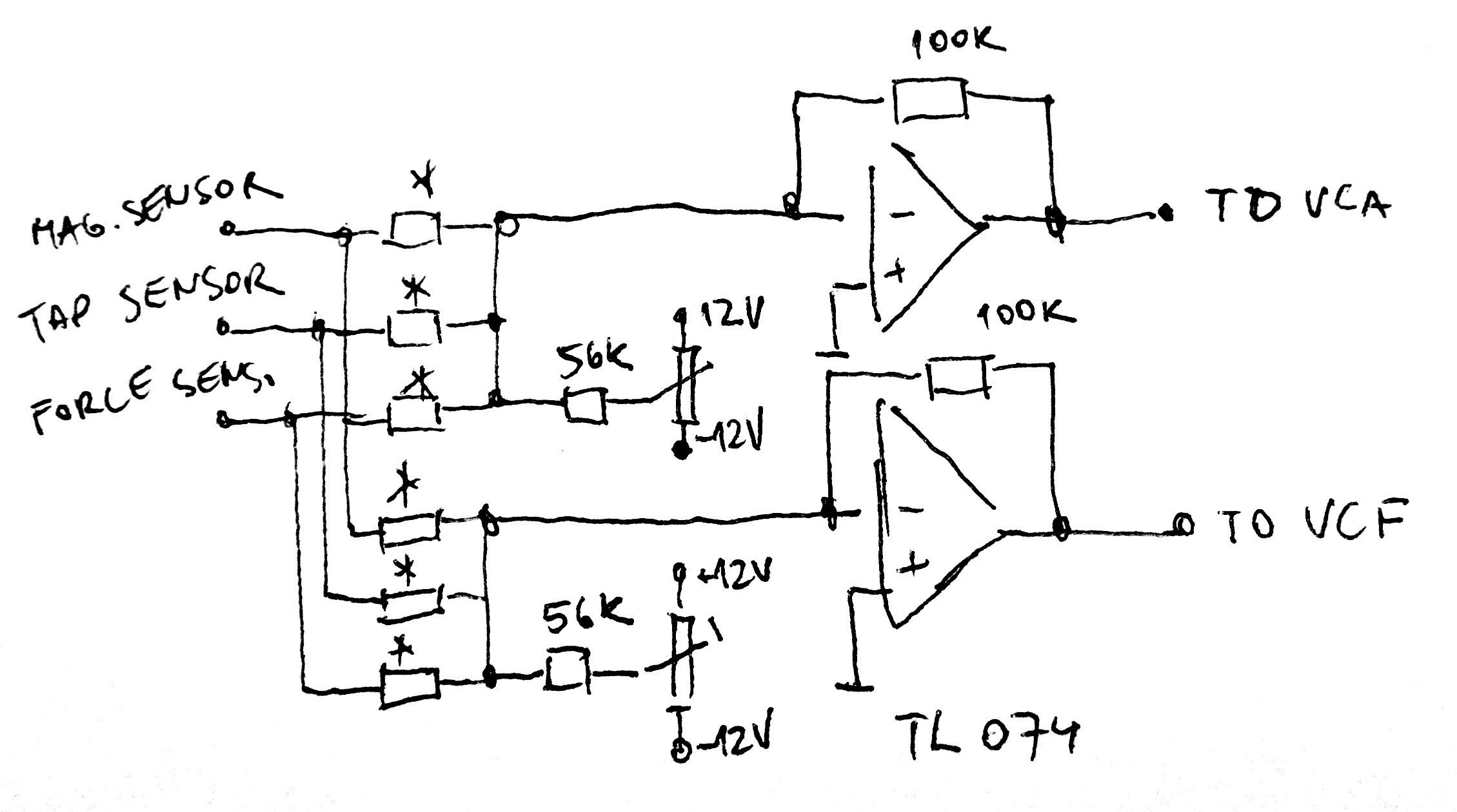
In order to mix signals from sensors in desired ratios, I used again two inverting summing amplifiers, one for VCA and another for VCF. The schematics for one string looks like this:
![]()
There is six resistors marked with asterisk, setting gain for each of three sensors for both VCA and VCF. In fact, I used only four resistors - I didn't need the force amplifier to set gain (volume), only filter (tone color). Similarly, tap sensor only affected gain, not filter.
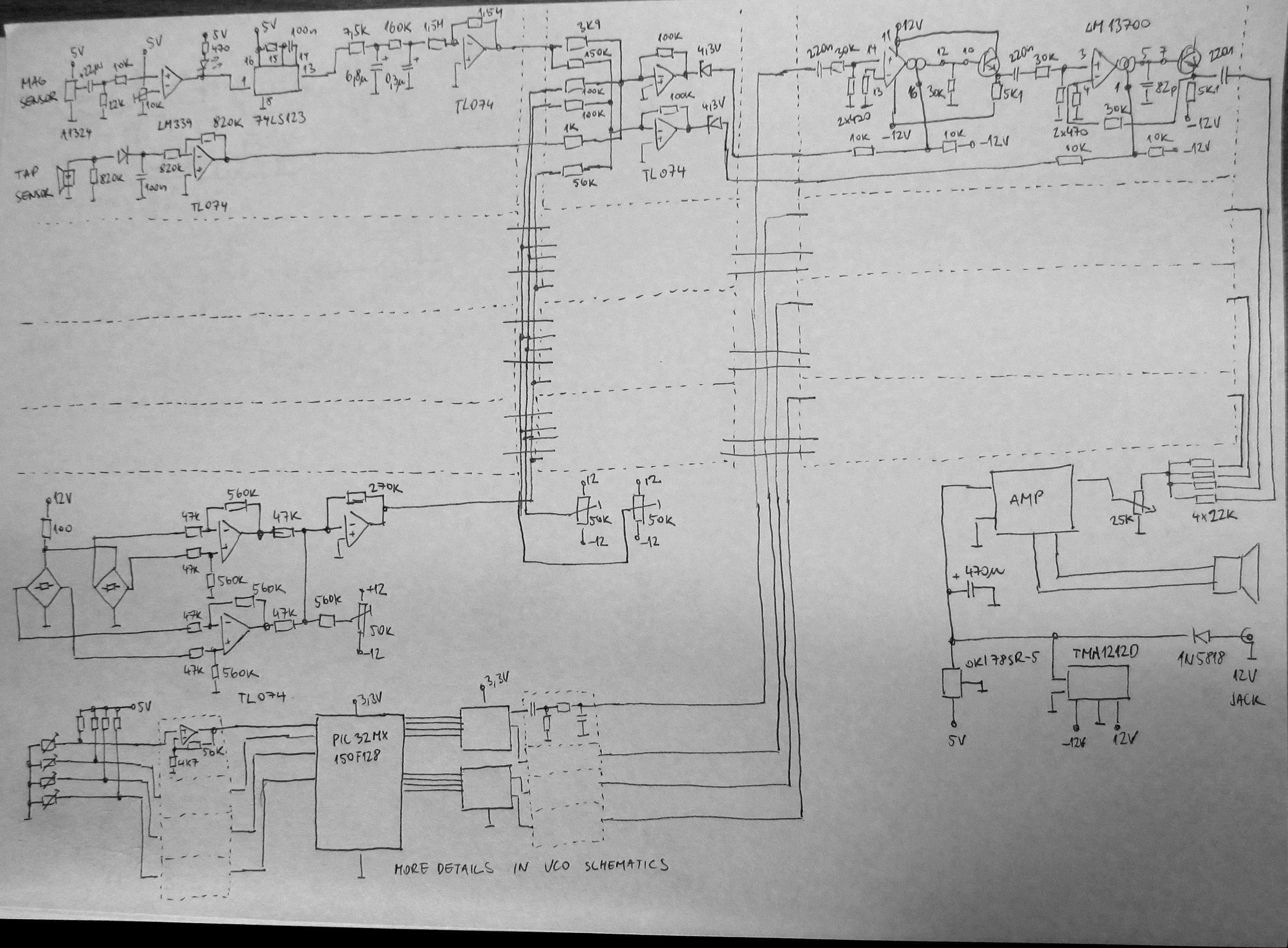
The only electronic PDF document I have is for VCO, all others were not drawn and complete circuit of the instrument was worked out on the go (improvised), I just printed out pinouts of key parts - LM339, LM13700 and TL074. Since no electronic documentation exists, I drew the complete schematics by hand:
![]()
Notice a few quadrupled blocks - as there are four strings, requiring four separate sound channels. The amplifier is ready to go TDA7266 module, I was lazy.
Next-day edit: It looks awful. I redrawn the schematics in proper schematics editor. See files section, please.
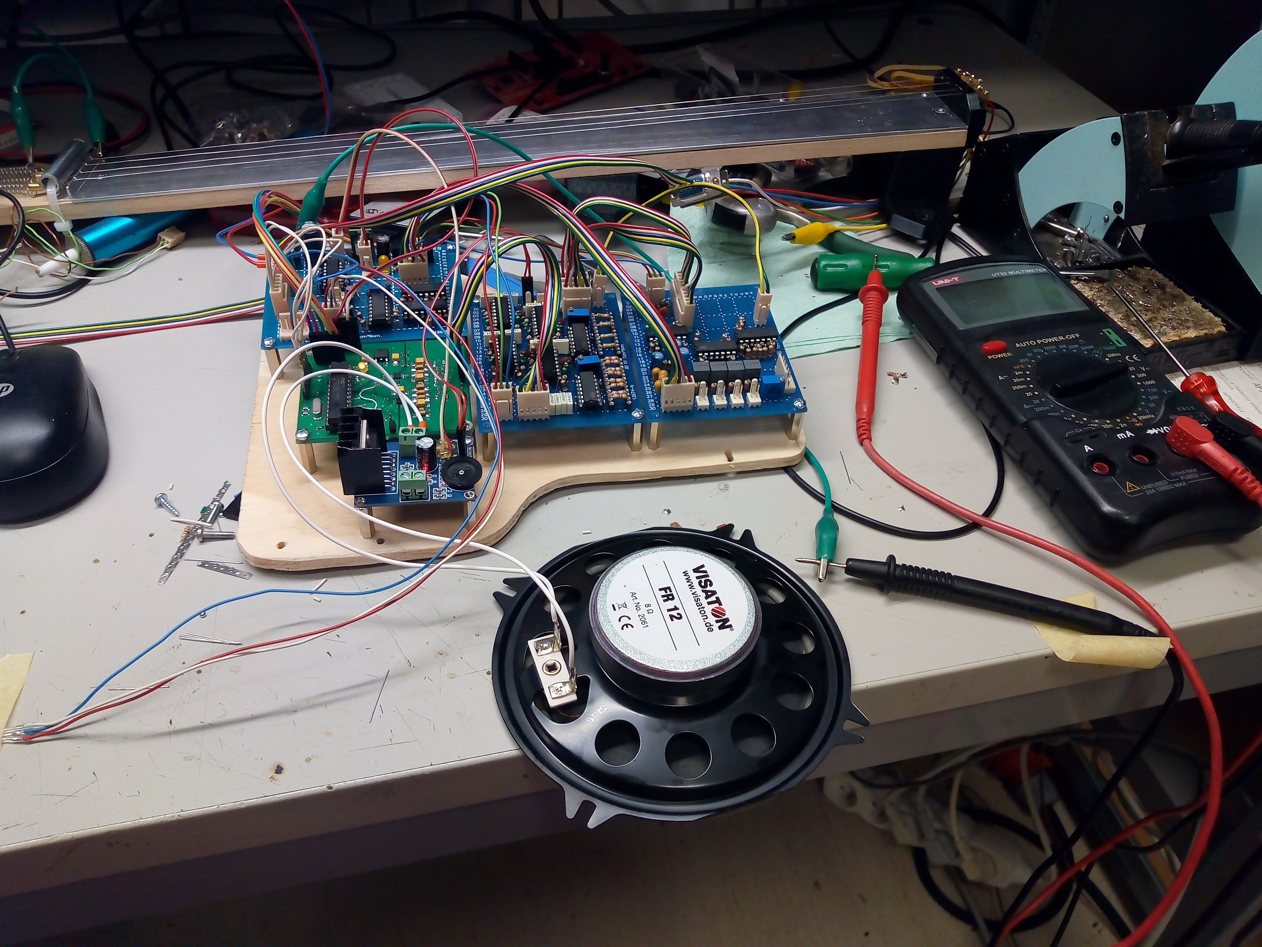
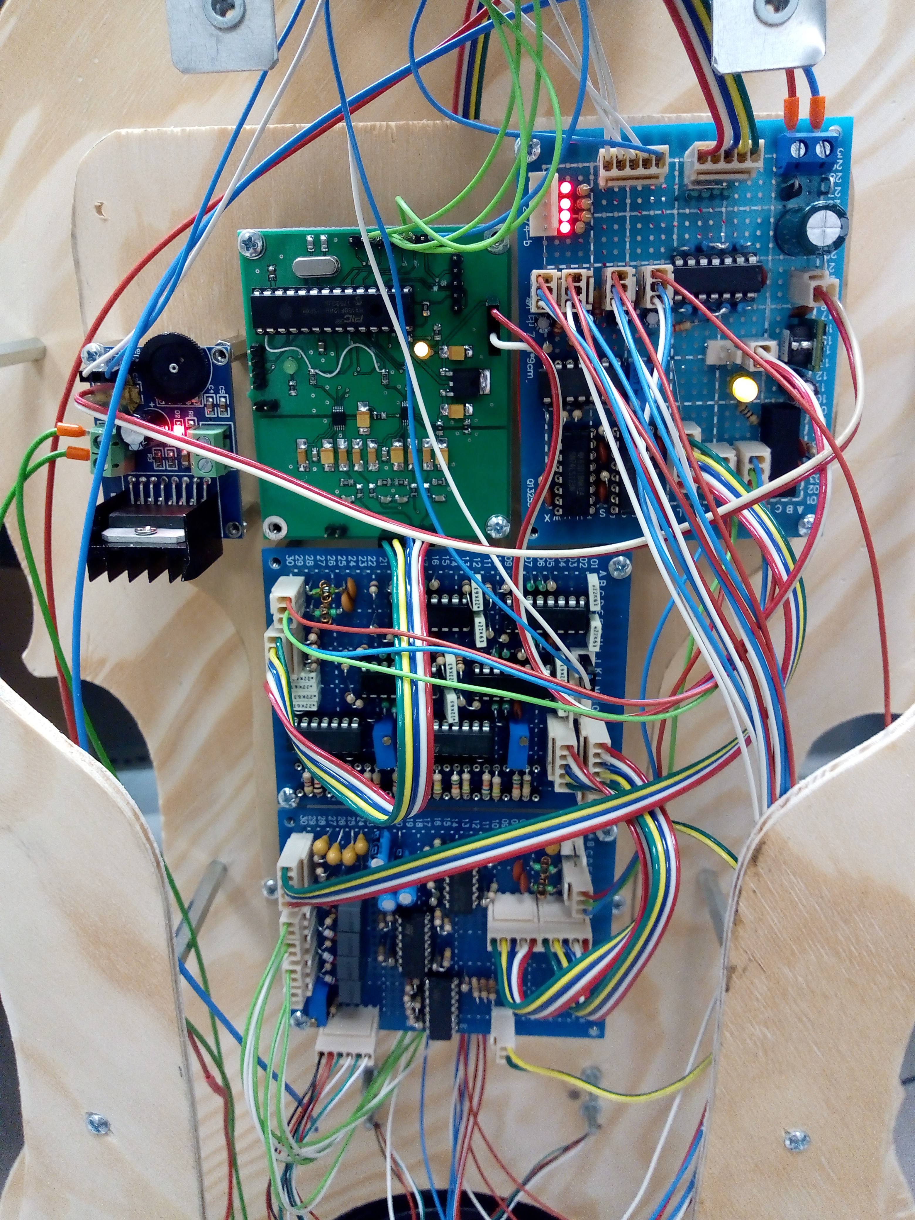
Complete electronics on plywood sub-panel
![]()
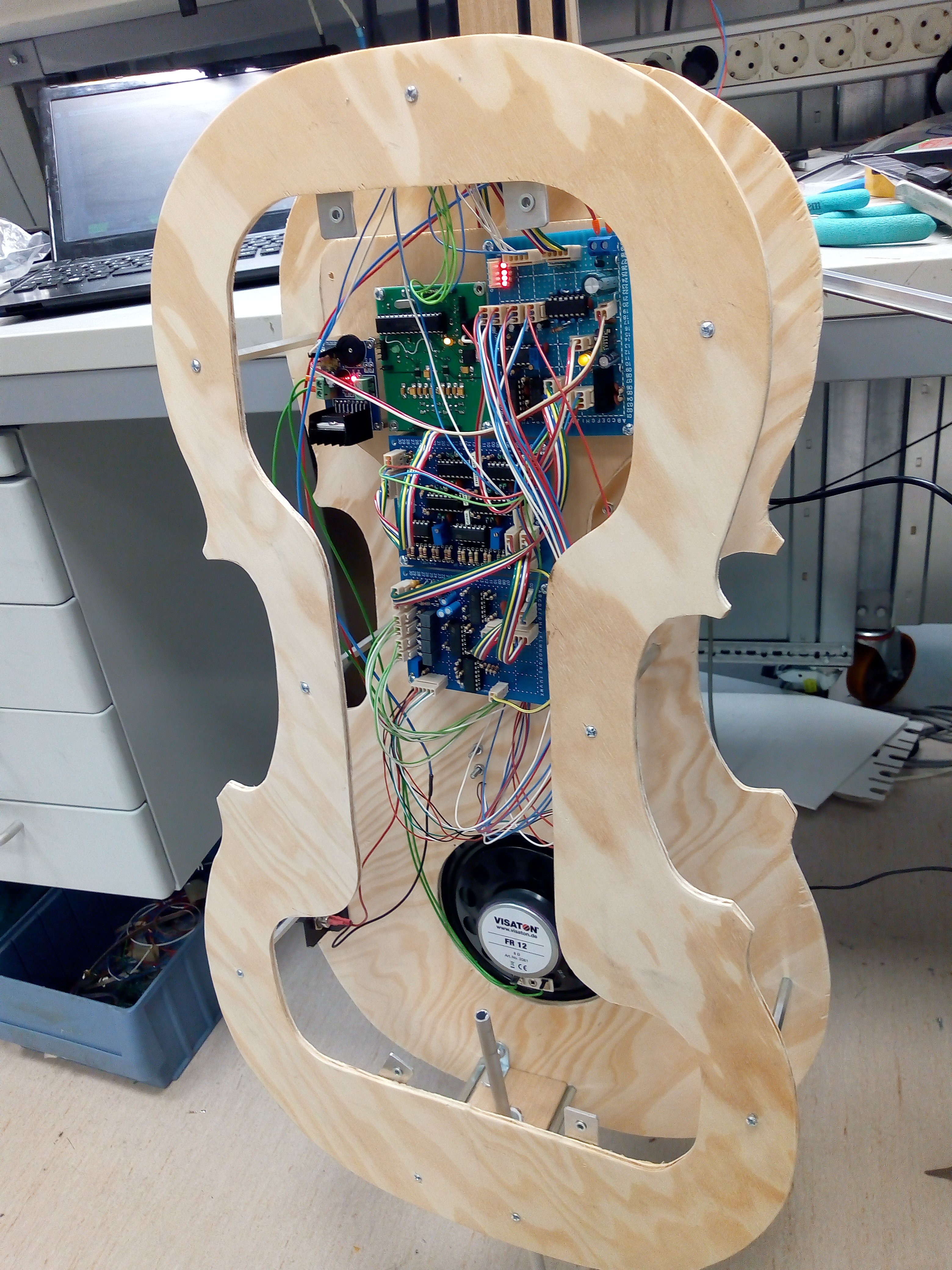
Mounted into instrument
![]()
![]()
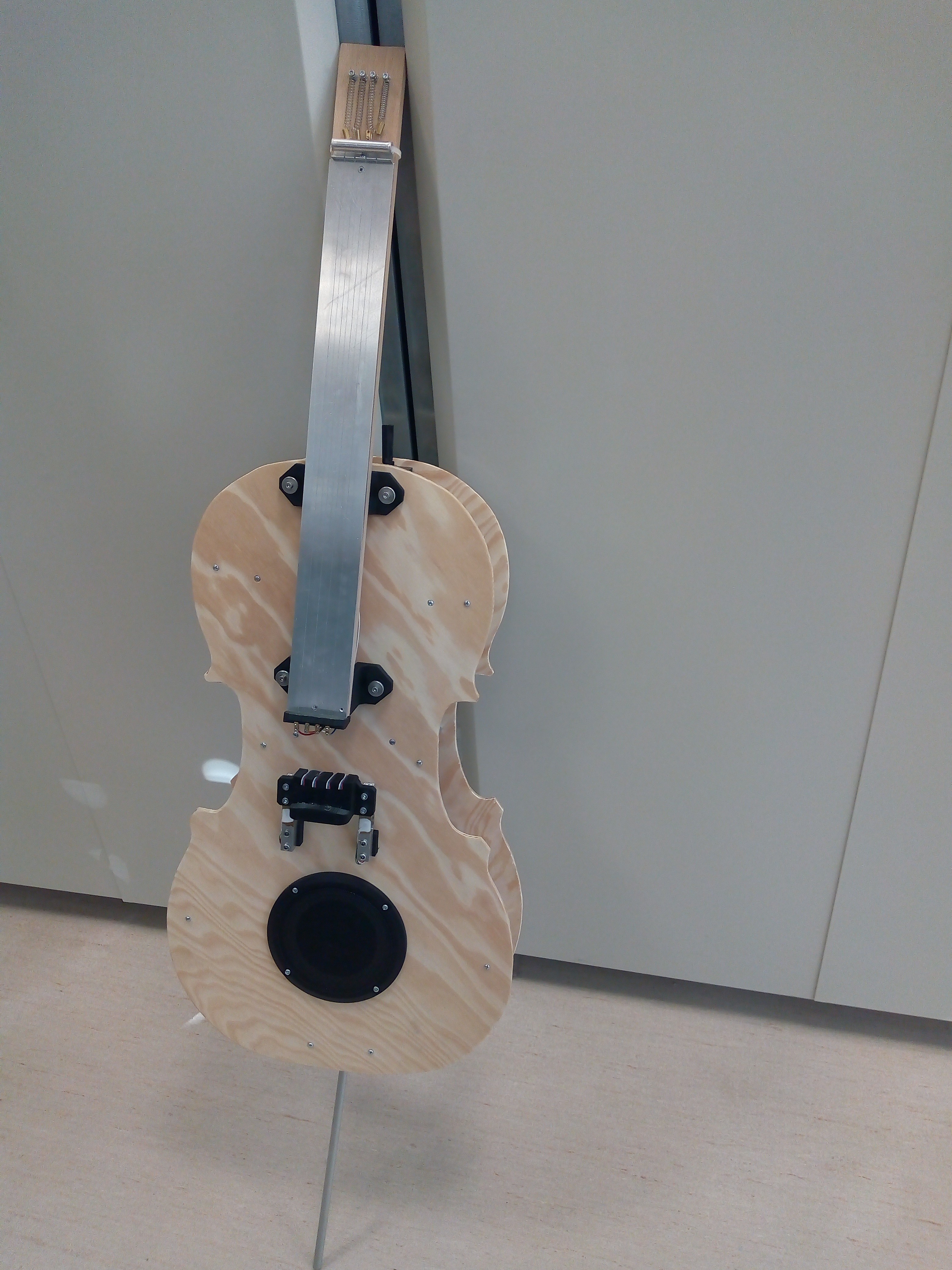
And complete instrument
![]() Added are some more photos capturing bow and detail of strings fixation
Added are some more photos capturing bow and detail of strings fixation![]() Bow is magnetic strip - this one, but there are more manufacturers of similar thing. The string is glued on 720mm piece of 10mm U-shaped aluminium extrusion.
Bow is magnetic strip - this one, but there are more manufacturers of similar thing. The string is glued on 720mm piece of 10mm U-shaped aluminium extrusion.![]() Resistor wires are fixed to steel wound strings - to keep resistor wire in mechanical tension - via brass screw terminals. Terminals are soldered together via piece of wire. I added aluminium round tube to press the strings against the end of fingerboard - L shaped aluminium extrusion with four cuts where strings of resistor wires are held in position.
Resistor wires are fixed to steel wound strings - to keep resistor wire in mechanical tension - via brass screw terminals. Terminals are soldered together via piece of wire. I added aluminium round tube to press the strings against the end of fingerboard - L shaped aluminium extrusion with four cuts where strings of resistor wires are held in position.
Other end of wires goes into brass screw terminals to be connected to wires going to instrument.![]() Whole fingerboard assembly is detachable, along with bottom pin, so dimensions of cello can be decreased for easier traveling or so.
Whole fingerboard assembly is detachable, along with bottom pin, so dimensions of cello can be decreased for easier traveling or so.![]()
-
Ply-woodworking
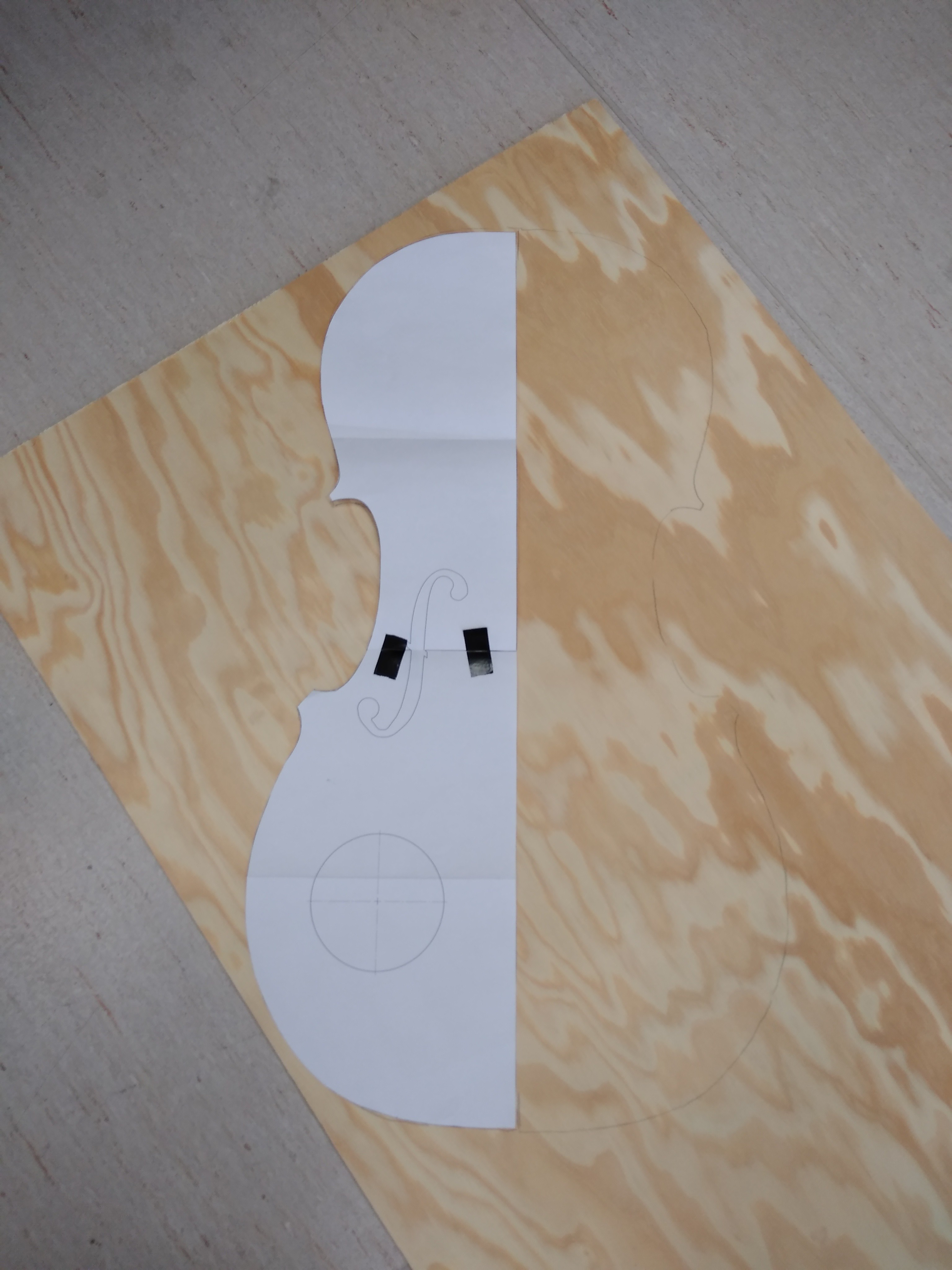
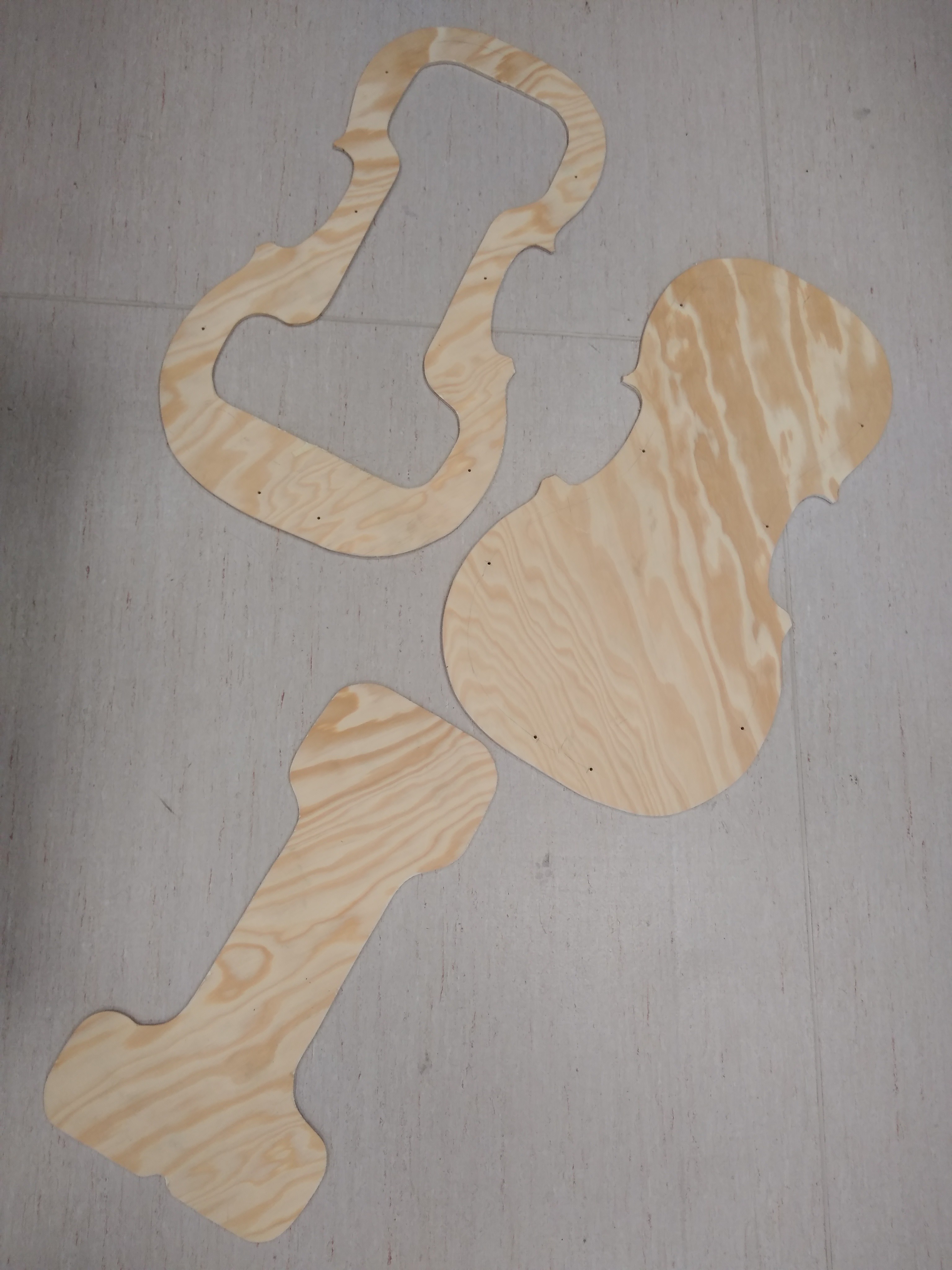
10/05/2018 at 22:46 • 0 commentsI must admit I'm not experienced woodworker, so I asked my colleague to help me out a bit. We drew a shape of cello body on paper, cut out and used as form to be retraced on 6mm thick plywood.
![]()
This was cut twice, for both faces of instrument body.
![]()
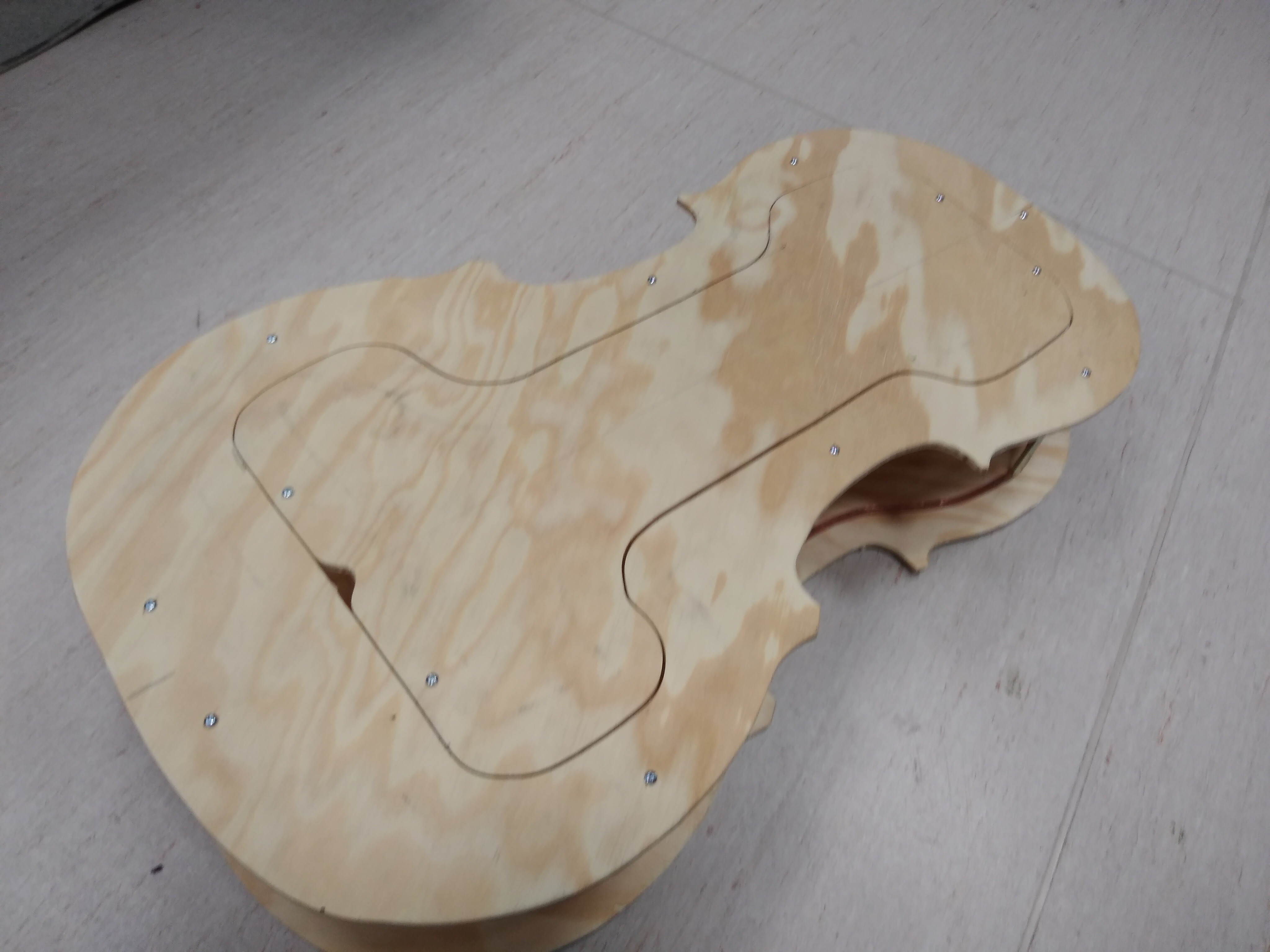
Backside has I-shaped cutout, to insert electric parts later.
![]()
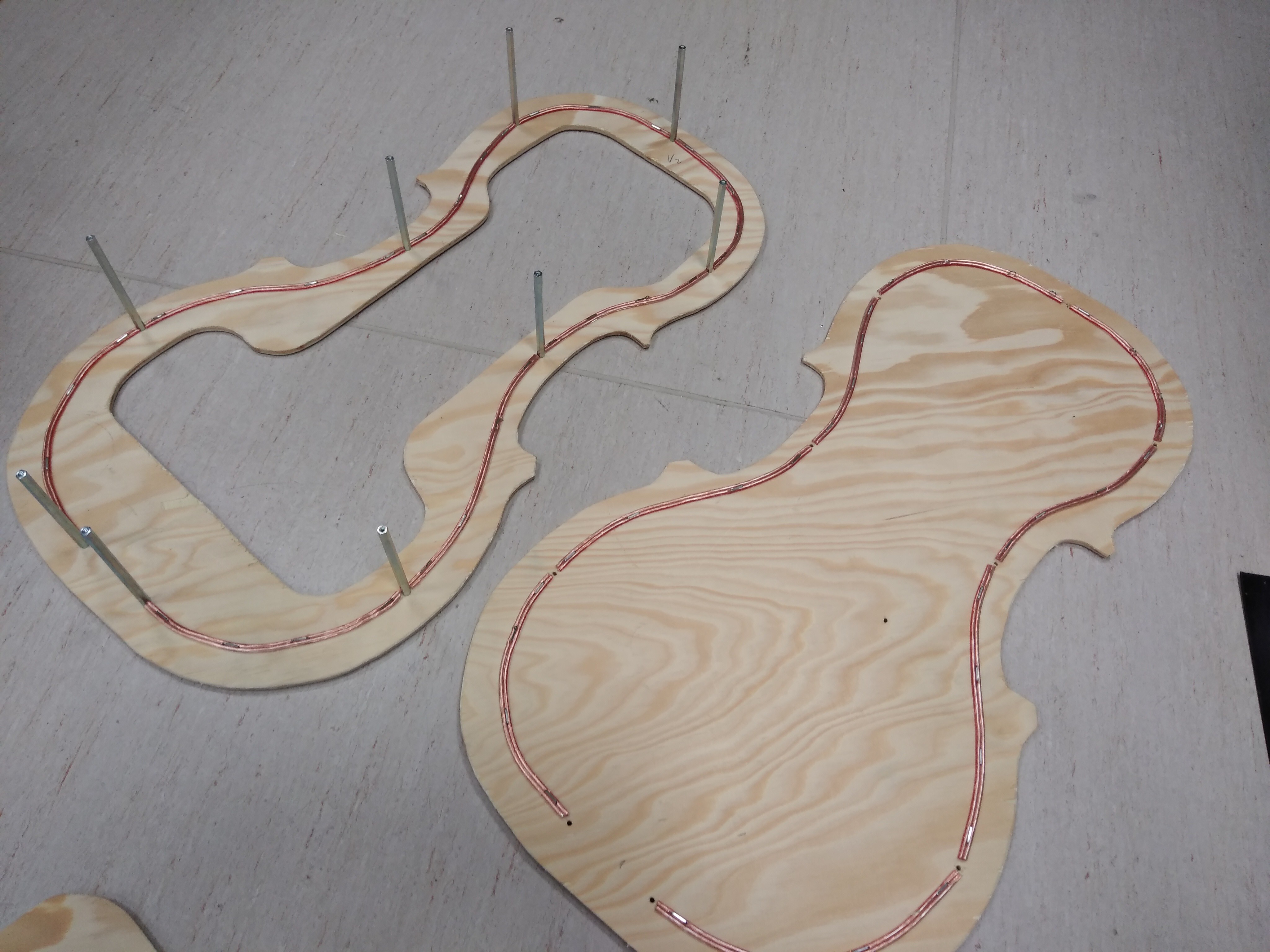
Metal spacers are to keep the halves together. Notice the wire stamped to inner faces - this was planned to keep polycarbonate shell forming side walls in place; unfortunately the polycarbonate was difficult to bend into desired shape, so we scrapped the idea, leaving only front and backside of the instrument.
![]()
Backside cutout back at place.
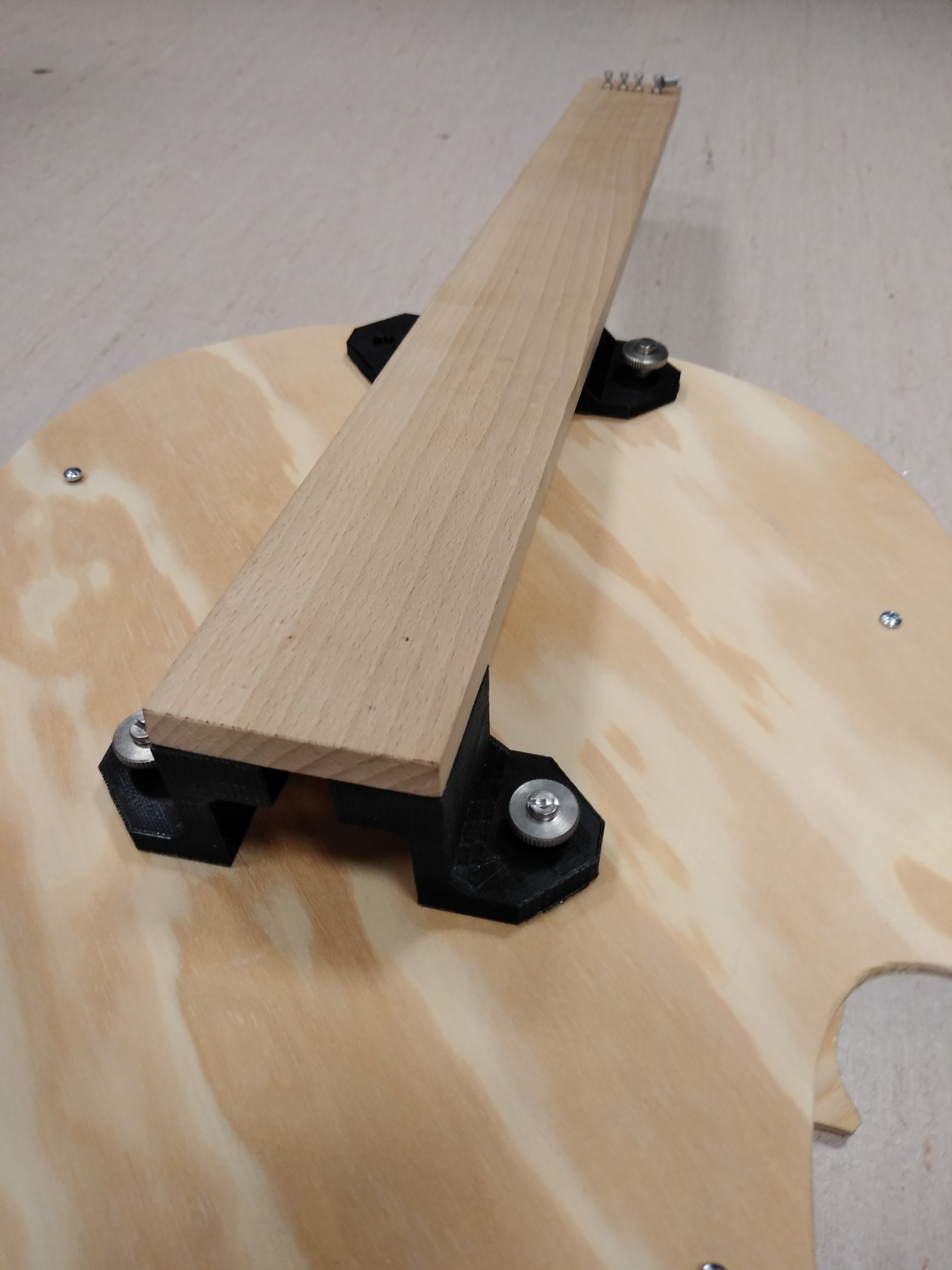
Fingerboard was made of single 50x6x1cm wood block, with 3D printed parts holding it in place
![]()
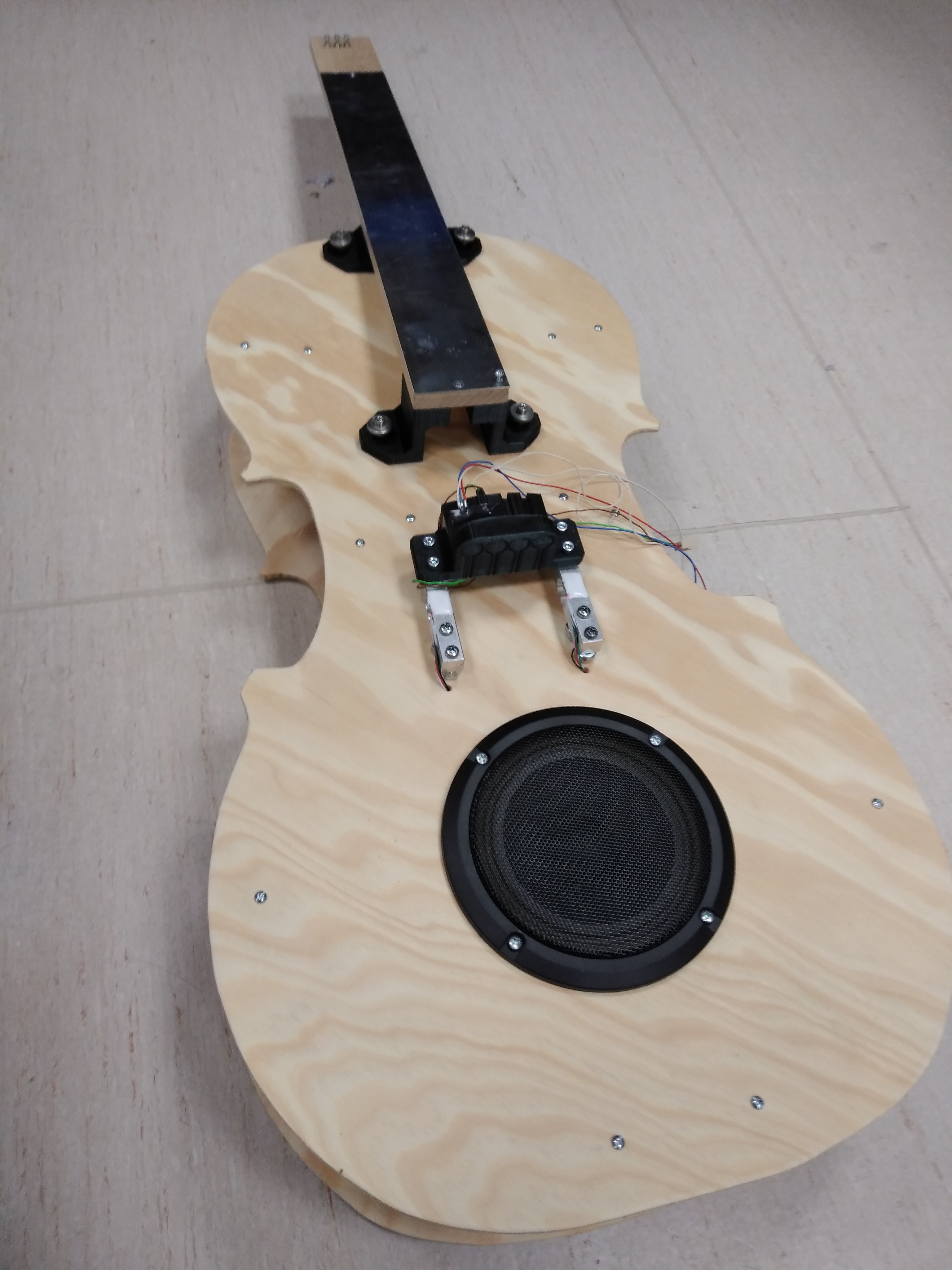
Here is picture of complete body, with cutout for speaker and sensor head installed in place
![]()
-
Three kinds of sensors
10/05/2018 at 22:22 • 0 commentsWhen playing this instrument, player has three ways of coloring its sound:
1, Magnetic sensors, one for each string. This one in engaged by drawing the magnetic strip bow across the sensor.
2, Tap sensors, again, one sensor for each string. Those are ordinary piezo speakers, placed under magnetic ones, are actuated by tapping fingers against the sensor, making pizzicato sound (equivalent to plucking the string of real cello with fingers).
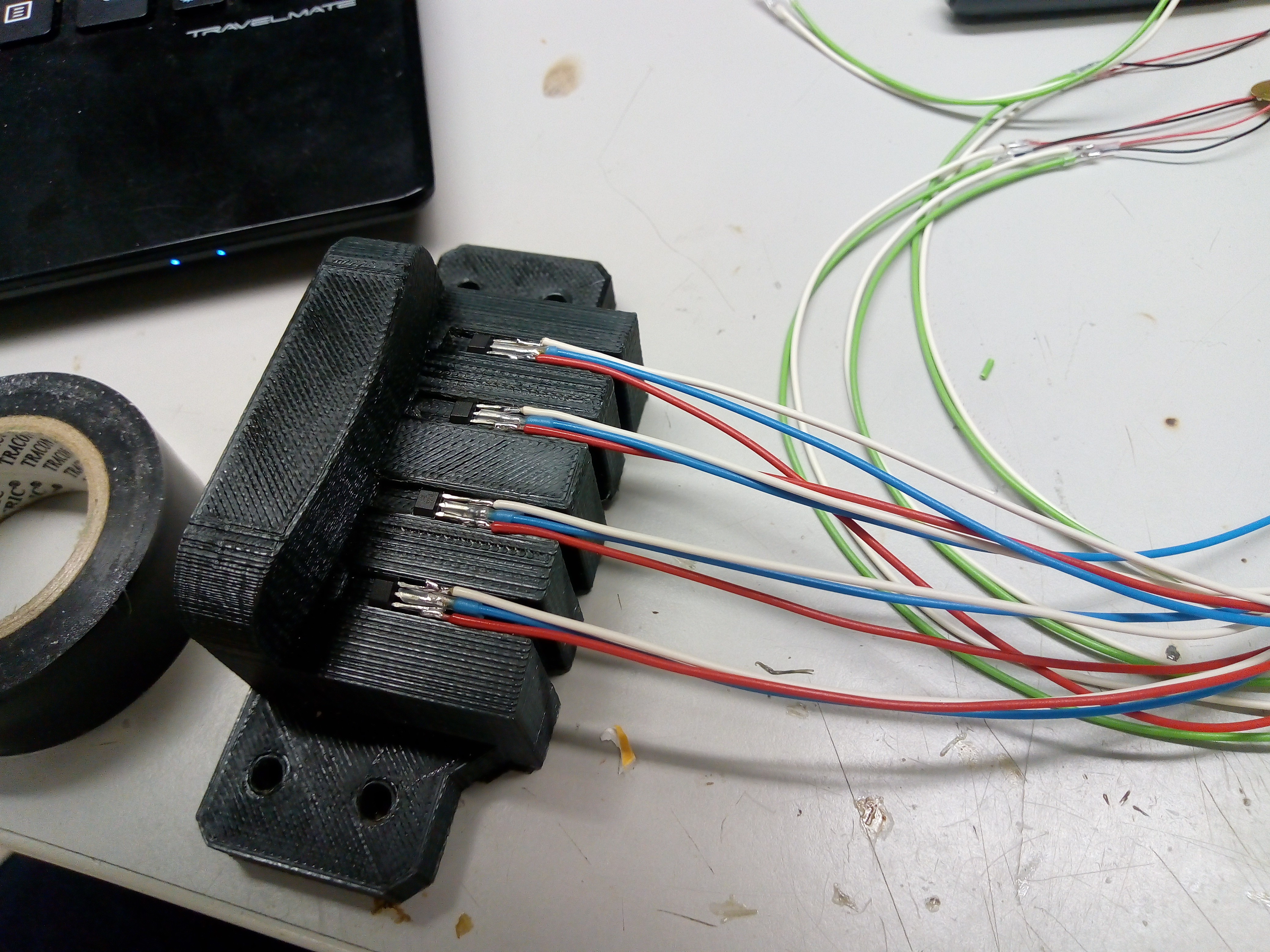
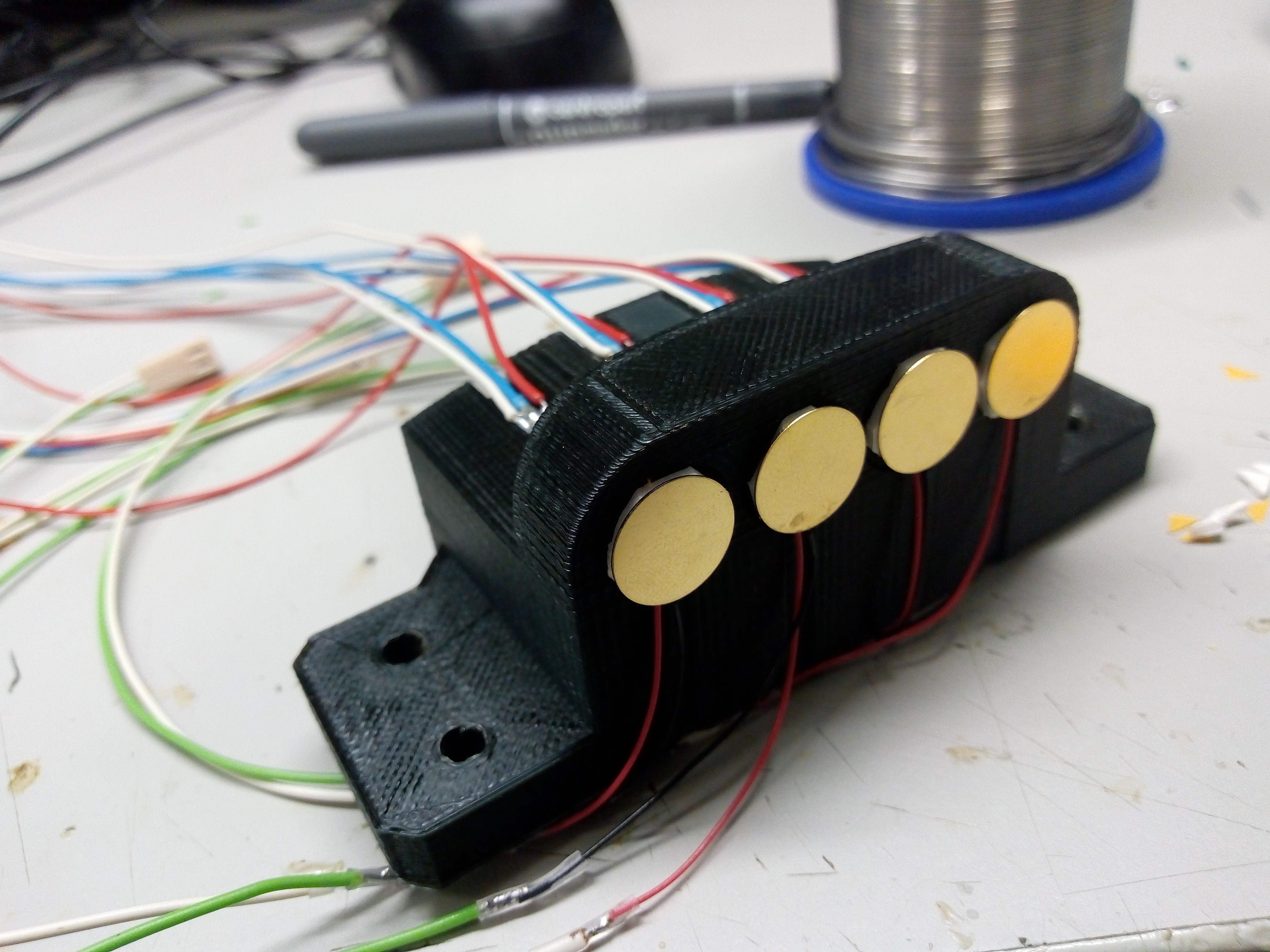
Both the sensors are placed on 3D printed sensor head
![]()
![]()
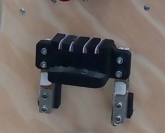
3, Force sensor - converting pressure of bow to electric signal. This is done by pair of 1kg load cells, carrying the sensor head.
![]()
First two sensors are mean to change gain of VCA (influencing sound volume, dynamics), force sensor is meant to adjust VCF, changing color of the tone, being generated as harmonics-rich sawtooth waveform in VCO.
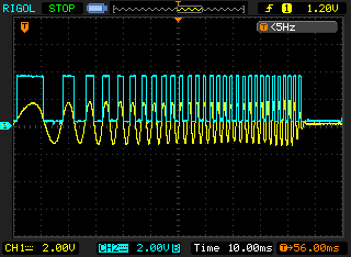
Magnetic sensor is based on A1324 from Allegro. This is linear hall sensor, its output voltage being proportional to magnetic filed present at sensors place. When moving the magnetic strip bow above the sensor, it generates sine-like waveform, with frequency proportional to speed of bow movement. I used comparator to convert this voltage to square waveform
![]()
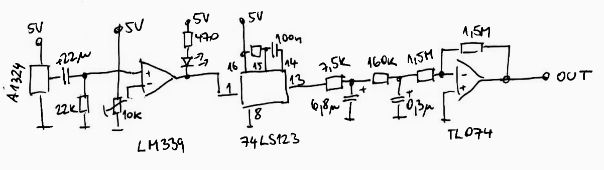
This is captured waveform of accelerating bow movement across the sensor (yellow line), along with comparator output. Now I have logic level signal, with frequency being proportional to desired variable (bow speed) and need to convert it to analog value to steer VCA. Here I can use old trick that multimeters use to meadure freqquency - monostable multivibrator 74LS123 to convert it to PWM signal with variable frequency, but constant pulse width. Then, it's just matter of low-pass RC filter to convert PWM signal to DC voltage. Complete schematics of single channel of magnetic sensor is here:
![]() The low-pass filter is followed by inverter providing both impedance buffering as well as inverting needed for following stages.
The low-pass filter is followed by inverter providing both impedance buffering as well as inverting needed for following stages.Tap sensor is somehow simpler, but took me longer to develop.
At first I thought of using resistive pressure sensors, but I couldn't get them to work very reliably. Accelerometers and microphones were considered too, but at the end I opted for cheap disc piezo transducer, like this
![]() Usually those are used as sound transmitters, ie. being driven with voltage and creating mechanical output (sound). Reverse operation is also possible, where mechanical input is creating voltage signal on its terminals.
Usually those are used as sound transmitters, ie. being driven with voltage and creating mechanical output (sound). Reverse operation is also possible, where mechanical input is creating voltage signal on its terminals. ![]() Main part of this circuit is resistor, diode and capacitor. After tapping on the sensor, voltage spike (blue waveform on picture below) charges the capacitor via diode, which is stopping its discharge when voltage on transducer is negative. Capacitor then slowly discharges into 820k - input impedance of the amplifier - see yellow waveform.
Main part of this circuit is resistor, diode and capacitor. After tapping on the sensor, voltage spike (blue waveform on picture below) charges the capacitor via diode, which is stopping its discharge when voltage on transducer is negative. Capacitor then slowly discharges into 820k - input impedance of the amplifier - see yellow waveform. ![]()
This circuit produces impulses with roughly exponential waveform, suitable for waveform shaping to emulate percussive sound of string being plucked with fingers.
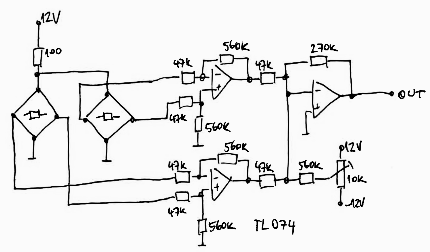
Force sensor is just textbook use of load cells. I'm using differential amplifiers for the task
![]()
Outputs from amplifiers are brought into summing amp, along with trimmer output, allowing to bring offset and zero out the weight of sensor head.
Now I described a lot of separate blocks - VCO, VCA, VCF, sensors and amplifiers. In following projects logs I'll try to make sense of all of it, linking all the parts together.
-
VCO, VCA, VCF
10/04/2018 at 22:46 • 0 commentsBecause VCOs in analog synths are notorious for their instability and sensitivity to temperature, humidity, supply voltage and all other influences you can imagine, I decided to cheat here and use microcontroller here. With microcontroller, the output frequency is derived from local crystal driven oscillator, so I had one less thing to worry about.
Also, this is the only part of instrument I designed single purpose PCB for, so have electronic documentation for it. For all other blocks are hand-drawn schematics all I have.
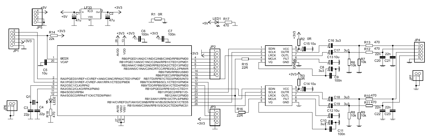
![]() Nothing surprising here - PIC32MX150F128B is driving pair of CS4344 stereo DACs, outputting 4 mono outputs in total. SPI interfaces of the PIC are brought to I2S mode and interrupt routine is feeding the DACs with increasing value, being reset after a while - creating sawtooth waveform, available as output of four separate oscillators on pinheader JP4.
Nothing surprising here - PIC32MX150F128B is driving pair of CS4344 stereo DACs, outputting 4 mono outputs in total. SPI interfaces of the PIC are brought to I2S mode and interrupt routine is feeding the DACs with increasing value, being reset after a while - creating sawtooth waveform, available as output of four separate oscillators on pinheader JP4.
Pinheader JP4 is populated to bring out analog pins of the MCU. Those analog inputs are used to steer oscillators inside the PIC. JP1 is used as ICSP header, JP3 being unused by now.
Schematics and board files in eagle 6 format, as well as PDF schematics and sources are available in files archive of this project.
VCA and VCF blocks will be somehow more amusing, using tactical ninja of all analog synths - LM13700.
This is how it looks for one channel, meaning this has to be copied four times for four VCO outputs:![]() It contains two halves of LM13700 in more-less databook application. It is powered by symmetrical +-12V. LM13700 is great chip and makes non-trivial tasks quite easy, though replicating this circuit four times on protoboard is rather daunting task. In order to minimize chance of mistake, I tested out the circuit on breadboard and measure its transfer across audible range.
It contains two halves of LM13700 in more-less databook application. It is powered by symmetrical +-12V. LM13700 is great chip and makes non-trivial tasks quite easy, though replicating this circuit four times on protoboard is rather daunting task. In order to minimize chance of mistake, I tested out the circuit on breadboard and measure its transfer across audible range.![]() Having all three VCx blocks is fine start for instrument, but it still lacks control circuits, translating players command (bow speed, bow pressure or "string plucking") into waveforms to control those blocks.
Having all three VCx blocks is fine start for instrument, but it still lacks control circuits, translating players command (bow speed, bow pressure or "string plucking") into waveforms to control those blocks. -
Block diagram
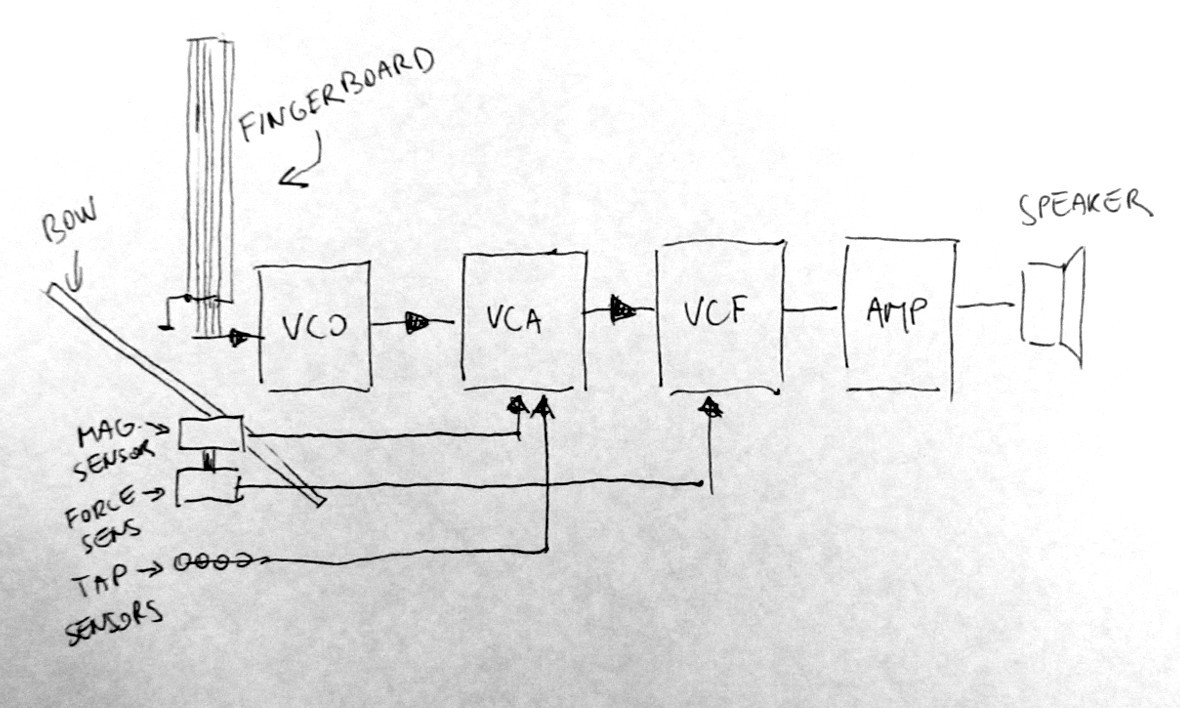
10/04/2018 at 21:45 • 0 commentsTo make my previous log somehow more accessible, I draw this block diagram:
![]()
The whole string instrument is a string (pun intended) of four blocks -
VCO - voltage controlled oscillator. This is the circuit that generates sawtooth tone proportional to its input voltage. The length of string of resistive wire over fingerboard can be measured by its resistance, transformed into voltage and fed into VCO.
VCA - voltage controlled amplifier. As name suggests, its transfer to output is related to input voltage. I can use it to "mute string" (shut down oscillator output) when no string is played.
VCF - voltage controlled filter. In this case, low-pass filter. This one can be used to change tone color, depending on how much of force is applied to the bow pickup sensors.
Finally, amplifier adjusts amplitude of the signals from VCO, VCA and VCF to fit loudspeaker, so the output from instrument can be heard.
Except of VCO all blocks are designed to use analog designers classic inventory - opamps, OTAs, and comparators. For the VCO, I cheated and used microcontroller and two stereo DACs. The instruments is somehow modular, so I can exchange it for proper analog VCO if I wanted to.
In following project logs, I'll describe the basic blocks in more detail.
-
First thoughts
10/04/2018 at 21:14 • 0 commentsThe idea of making cello-ish electronic instrument (other than using pickup to classic or reduced cello frame and sensing string vibrations) is certainly not new.
I've seen at least one implementation before, but honestly I was disappointed by little articulation possibilities of the bow. My idea was to use "physical" bow and sense its movement and pressure relative to the instrument, to allow more tone color, perhaps allowing to play more than one string at time (double stops) or even adding another sensors to allow "plucking" of the "strings" (pizzicato). Also, using strings on fingerboard - albeit not as oscillators itself, but merely as mean to determine what note wants the player.
The fingerboard part can be achieved by having four resistive wires above metallic fingerboard, having ground potential. When wire is pushed against metallic fingerboard, its length is decreased and its resistance drops. The wires will pass some current., this will result in change of voltage, that can feed the voltage controlled oscillator (VCO). Problem is that the oscillators will always work, unlike real cello, where oscillators (strings) resonate on players demand, dictated by bow movement.
As I wanted to have the bow "unplugged" from instrument body (just like for real instrument) I decided to make the bow from magnetic strip - this is steel strip, coated with ferrite magnet, which is then magnetized to have alternating magnetic domains, usually meant for precise length measurement. Then, I can employ four magnetic sensors in "pickup", each one belonging to one of oscillators. When bow is dragged across sensor, it produces impulses, whose frequency is proportional to bowing speed, usable as volume (amplitude) gate of the particular oscillator. What more, I can set up the sensors on force sensor, sensing pressure of bow - this can be input to color (frequency filter) of the oscillator.
To sense taps by fingers (pizzicato) I can employ touch sensors. I opted for piezoelectric ones, as those seemed to be most suited to sense dynamic pressure changes.
Well, it looks simply enough, huh? Stay tuned for new project logs.
Cello-like, mostly analog synth
Cello with bow and strings, though creating all sound electronically, in 70's synth way
 Added are some more photos capturing bow and detail of strings fixation
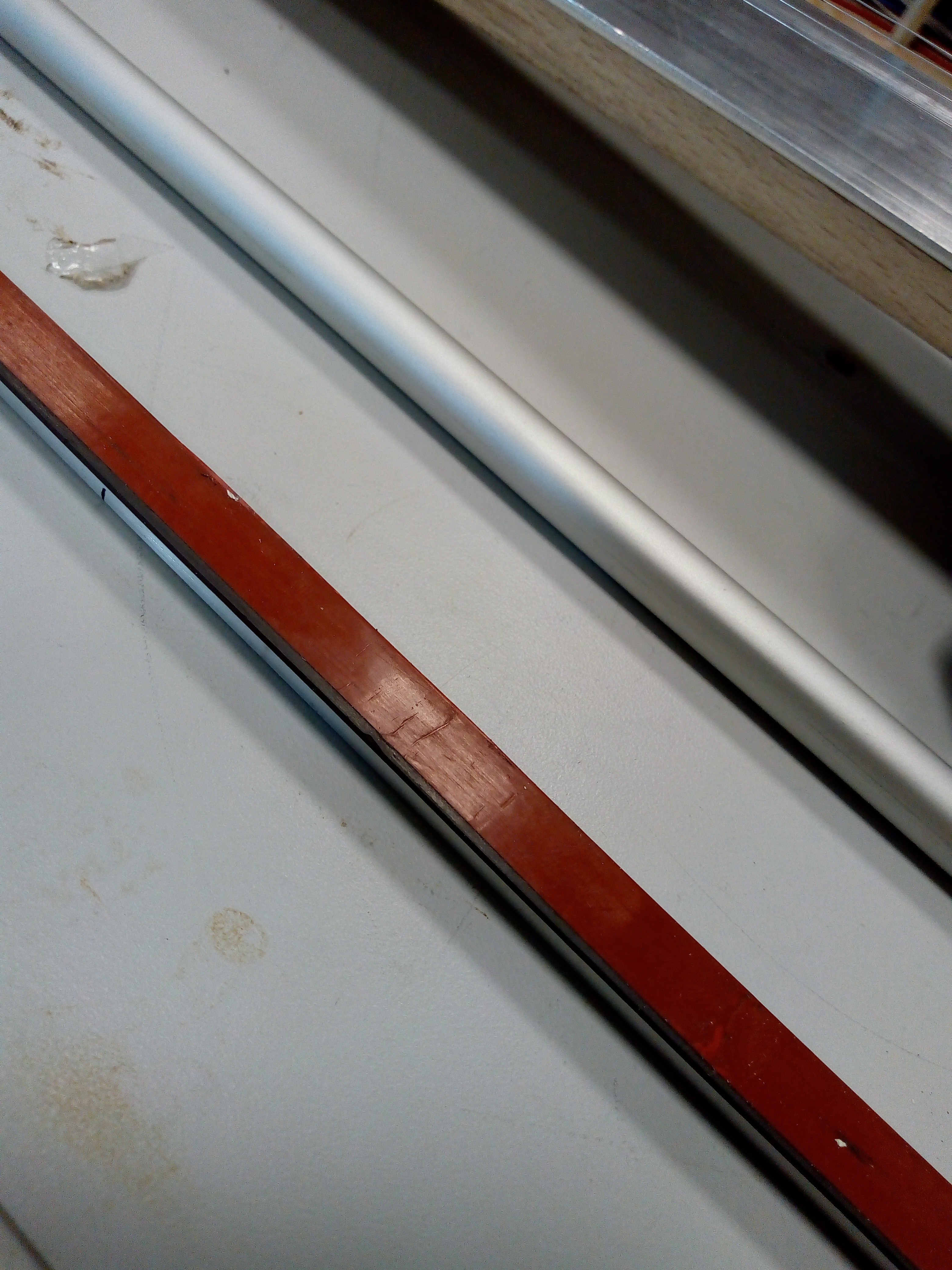 Bow is magnetic strip -
 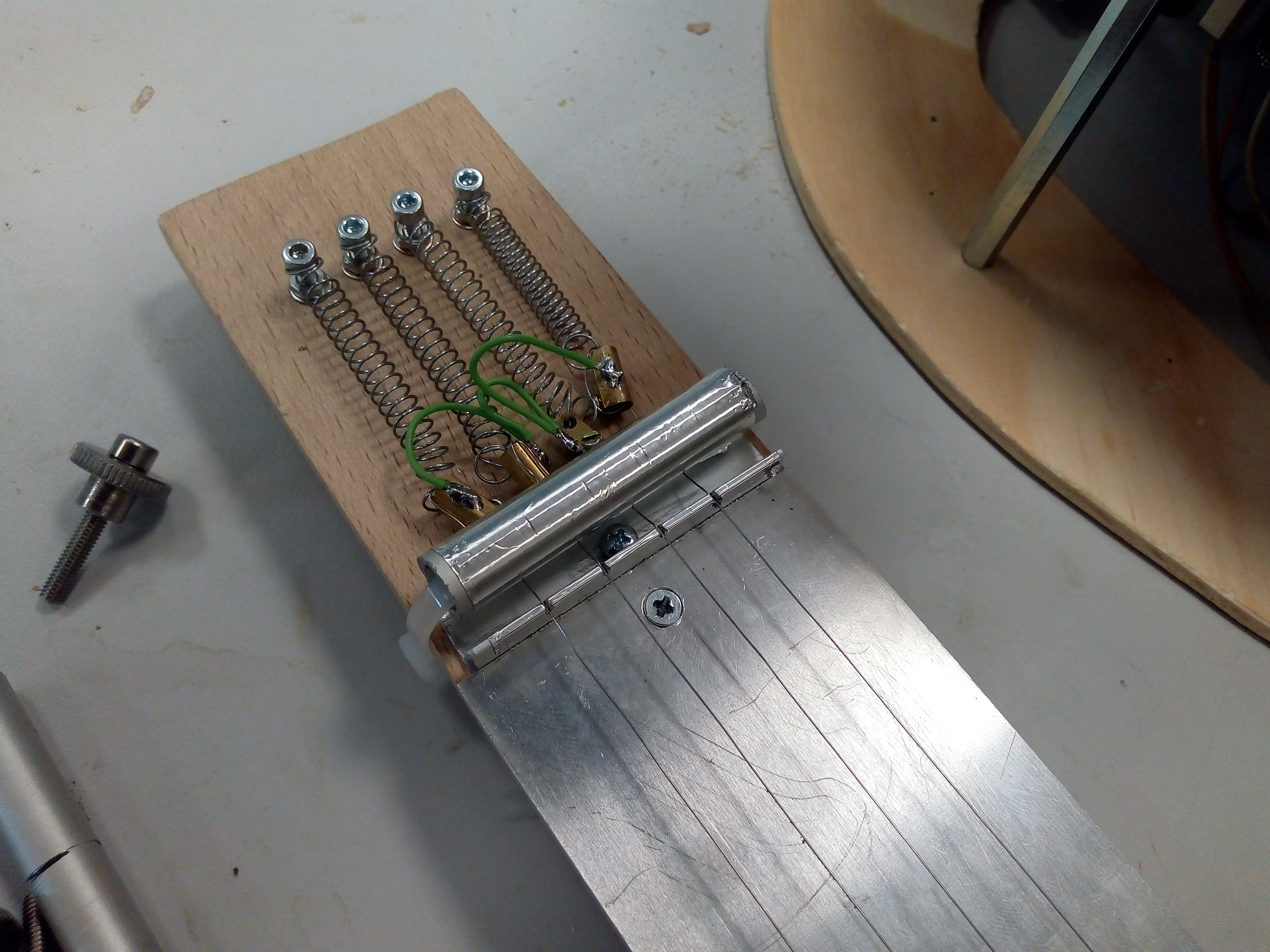 Resistor wires are fixed to steel wound strings - to keep resistor wire in mechanical tension - via brass screw terminals. Terminals are soldered together via piece of wire. I added aluminium round tube to press the strings against the end of fingerboard - L shaped aluminium extrusion with four cuts where strings of resistor wires are held in position.
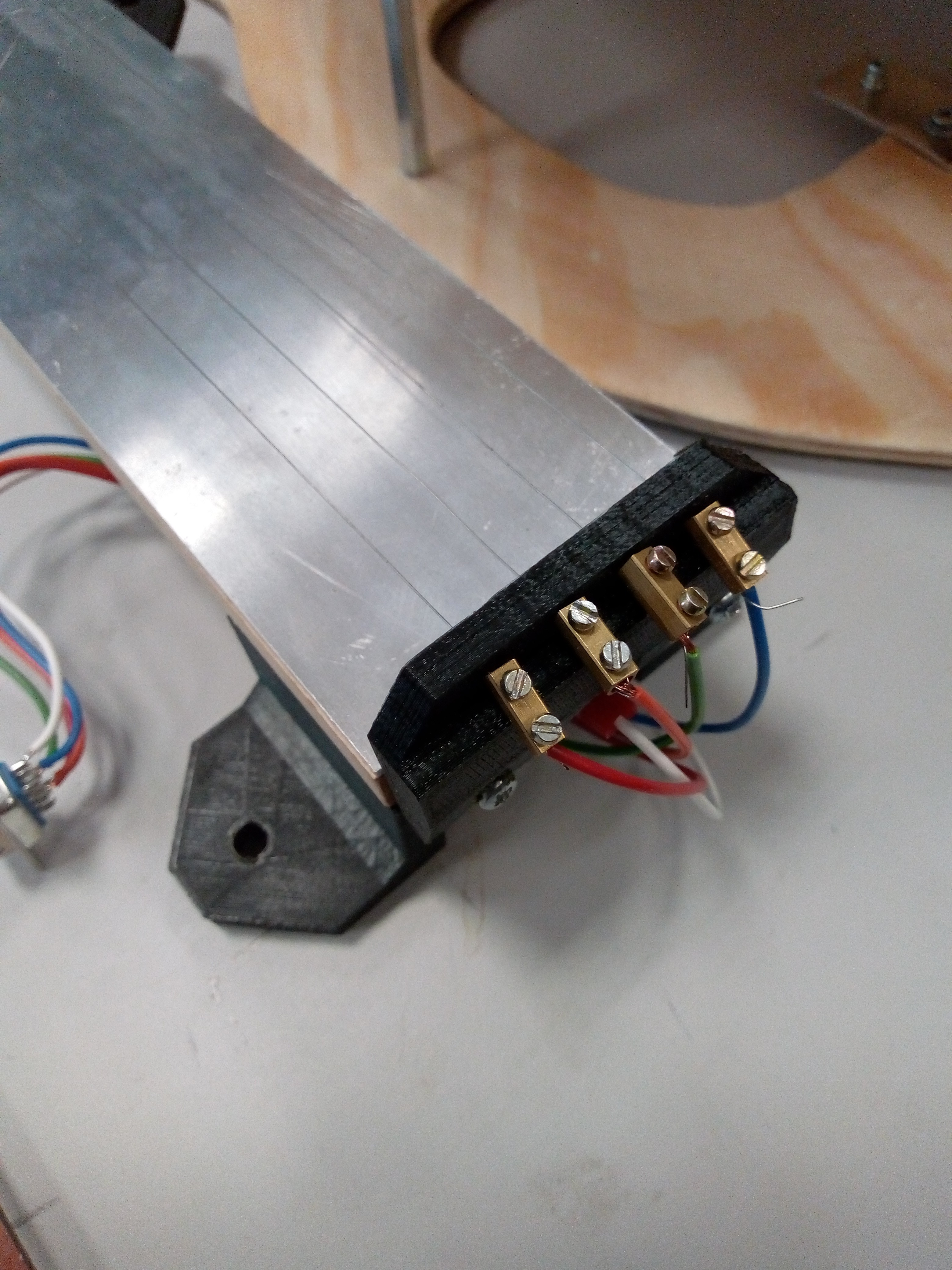 Whole fingerboard assembly is detachable, along with bottom pin, so dimensions of cello can be decreased for easier traveling or so.
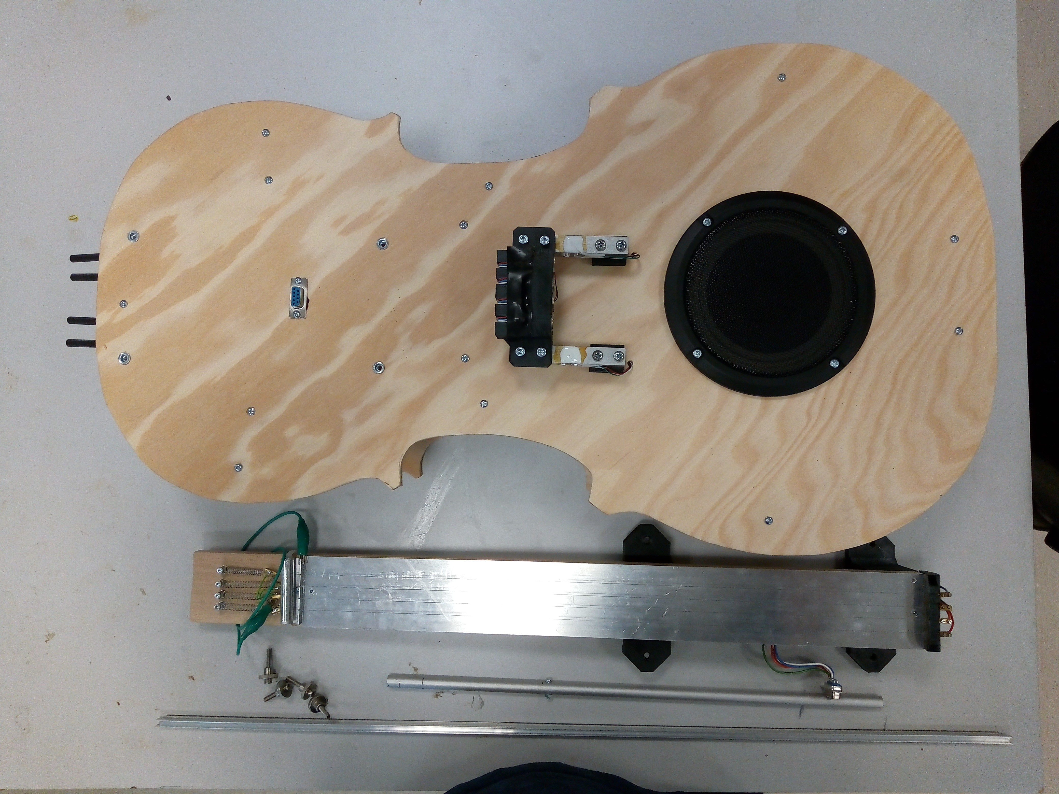
 The low-pass filter is followed by inverter providing both impedance buffering as well as inverting needed for following stages.
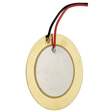 Usually those are used as sound transmitters, ie. being driven with voltage and creating mechanical output (sound). Reverse operation is also possible, where mechanical input is creating voltage signal on its terminals.
 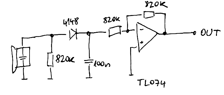 Main part of this circuit is resistor, diode and capacitor. After tapping on the sensor, voltage spike (blue waveform on picture below) charges the capacitor via diode, which is stopping its discharge when voltage on transducer is negative. Capacitor then slowly discharges into 820k - input impedance of the amplifier - see yellow waveform.
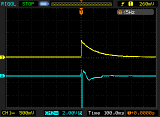
 Nothing surprising here - PIC32MX150F128B is driving pair of CS4344 stereo DACs, outputting 4 mono outputs in total. SPI interfaces of the PIC are brought to I2S mode and interrupt routine is feeding the DACs with increasing value, being reset after a while - creating sawtooth waveform, available as output of four separate oscillators on pinheader JP4.
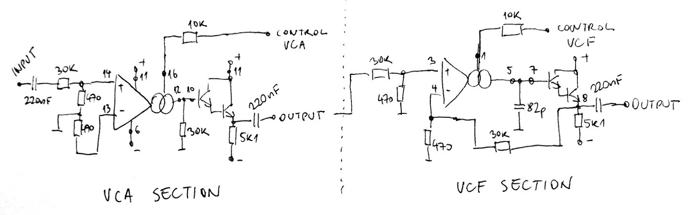 It contains two halves of LM13700 in more-less databook application. It is powered by symmetrical +-12V. LM13700 is great chip and makes non-trivial tasks quite easy, though replicating this circuit four times on protoboard is rather daunting task. In order to minimize chance of mistake, I tested out the circuit on breadboard and measure its transfer across audible range.
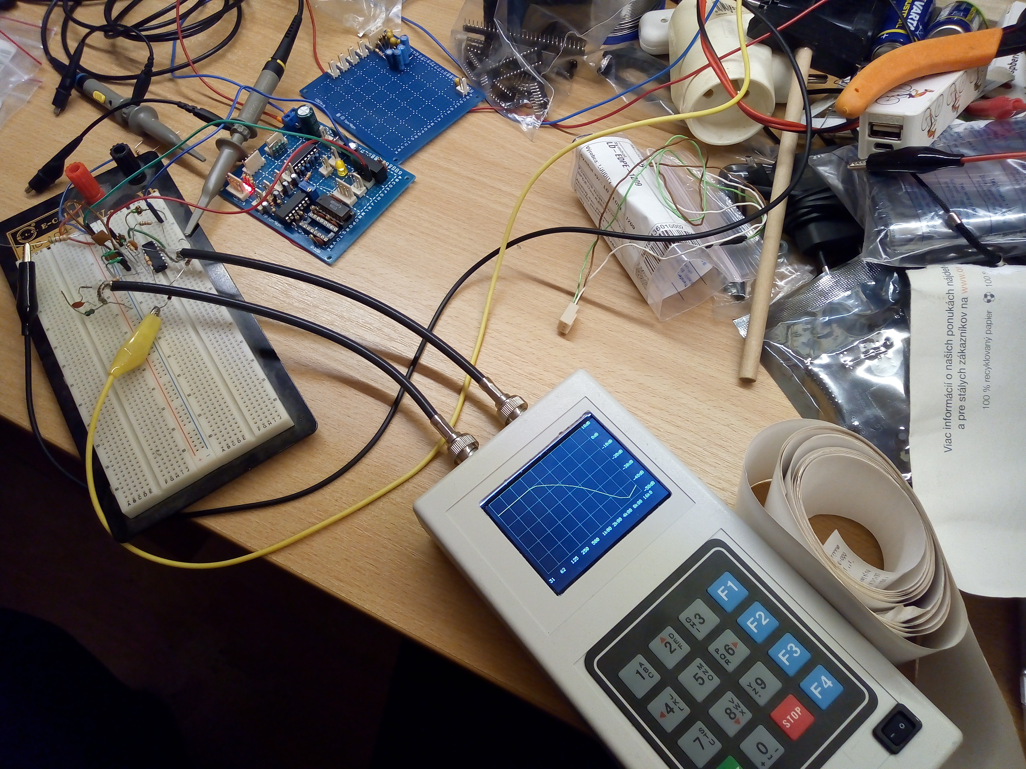 Having all three VCx blocks is fine start for instrument, but it still lacks control circuits, translating players command (bow speed, bow pressure or "string plucking") into waveforms to control those blocks.