-
101 Preface
If you want to build the ElektroCaster, here are some aspects you want to consider before you start:
- This isn't for somebody who just want‘s to get the needed parts and assemble it like a diy-guitar-kit (yet). There will be some hurdles to take and difficult manual labor to make.
- Although this is a working prototype, this project is still (and may allways will be) work in progress. Software and interface are hardly developed yet.
- Think of it like a protoyping platform: wack in a new headstock with robotic tuning features, try a new actuator beneath the strings or change the neck over an improved one – thanks to the modular design, all of this can be relatively easy achieved.
- There is not "the one ElektroCaster". It's parametrically designed in OpenScad, which is why many features can be changed: The number of the strings, the length of the scale, the spacing between the strings (at neck and bridge positions) or the number of frets can all be edited whithin the parameters.scad file. That means, you could also make a small four-string-ukulele-version out of it.
Tools that you might not have:- A big 3d-printer with 400x400x400 build volume, because there are many big parts, which can't be split easily.
- A cnc-router or laser-cutter wtih a build size bigger than the body (322x396mm).
- A method to make the pcbs, I used my cnc-router.
-
202 The Slot-Body
The core of the ElektroCaster is made of aluminum V-Slot profiles. I started whith a v-slot-starter-kit from RatRig, which I do recommend to get.
For the slot-frame you‘ll need the following parts:
- 3 x 50cm, 2020 v-slot profiles
- 6 x M5, 40mm screws
- 4 x M5 t-nuts
And this tools:
- Saw
- Screwdriver
- Tab to make M5 threads.
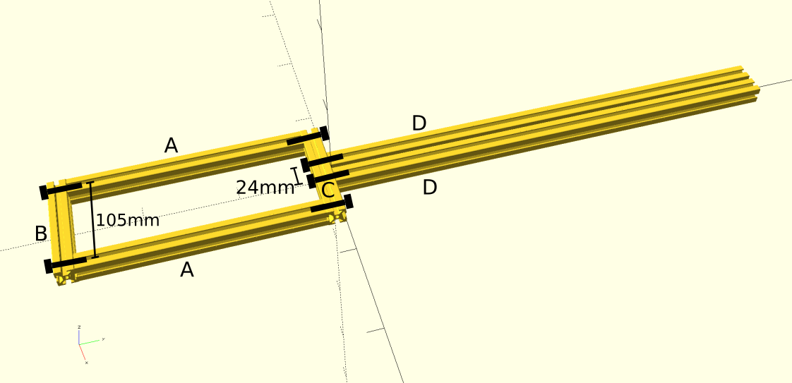
1) Cut the profiles so that you end up whith the following lengths: 2 x 50cm(D), 2 x 25 cm(A), 4 x 12.5(B,C,E).
2) Drill some 5mm holes to screw the parts A,B,C,D together. My v-slots allredy came with threads on both ends but since you cut them, you‘ll need to tab some threads to the A parts.
![]()
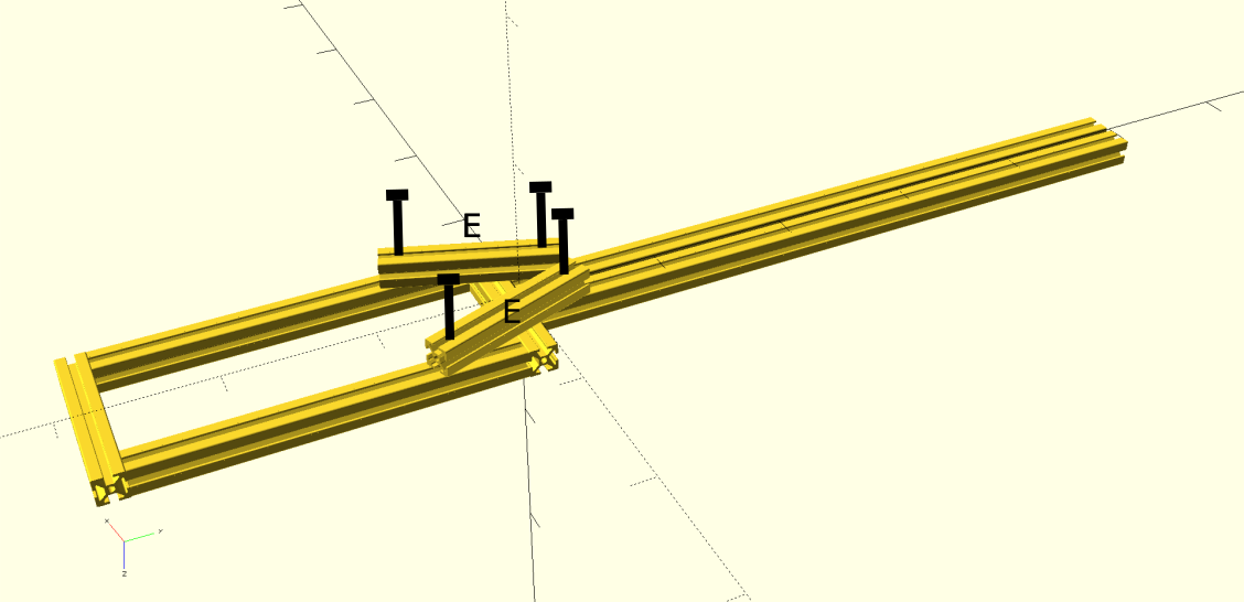
3) Drill holes near the ends of E and use t-nuts to connect them to A and D. There are no exact measures how to put them. They‘ll probably need to be adjusted when mounting the printed body in the next step (which is no problem since the n uts can be easily moved).
![]()
-
303 Print The Body-Frame
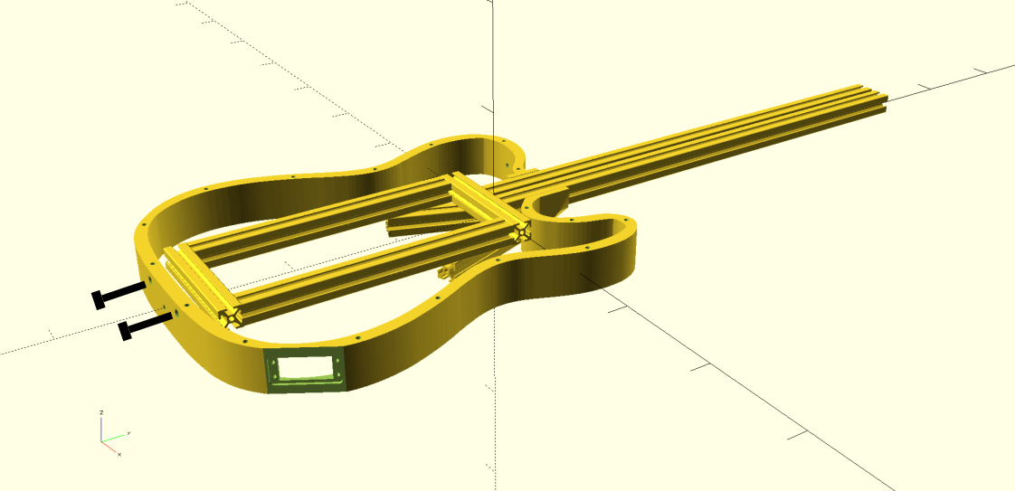
1) Print the body.stl file (/hardware/mechanical/stl/body.stl). I used a .6mm nozzle, .8mm extrusion width an .3mm layer height.
2) Attach the printed body-frame to the slot-body using M5 screws and t-nuts. The screws need to be cut to length.
![]()
One screw doesn't need a t-nut as it's directly put into the slot-body. This screw is one of those you allready used in step 2. I don't think this is really needed so I may remove this in future versions.
![]()
 Frank Piesik


Discussions
Become a Hackaday.io Member
Create an account to leave a comment. Already have an account? Log In.