DIY Bluetooth SNES Classic Controller
Exactly as the title says, I built a bluetooth controller out of a SNES controller and dongle for use with Nintendo's mini classic consoles.
Exactly as the title says, I built a bluetooth controller out of a SNES controller and dongle for use with Nintendo's mini classic consoles.
To make the experience fit your profile, pick a username and tell us what interests you.
We found and based on your interests.
bt_controller.inoSNES Transmitter Firmwareino - 4.73 kB - 07/24/2023 at 12:03 |
|
|
reprogrammableBTcontroller.inoUSB Receiver Firmwareino - 13.95 kB - 07/24/2023 at 12:01 |
|
|
Arduino Pico.schsch - 563.35 kB - 07/24/2023 at 12:00 |
|
|
Arduino Pico.brdbrd - 91.82 kB - 07/24/2023 at 12:00 |
|
|
Arduino Pico_2018-09-24.zipx-zip-compressed - 129.71 kB - 07/24/2023 at 12:00 |
|
I've programmed an Arduino Leonardo (or any Atmega32U4 will work) to act as a keyboard in conjunction with the bluetooth controller I built. To make things more flexible to work with as wide of a range of games/emulators I decided to add the ability to remap every button to any keyboard key through a serial terminal. Open a serial terminal (tested using the one included with the Arduino IDE), set to 9600 baud, the correct COM port for the arduino, 8n1, no appended characters, type 'Help' for instructions, 'List' for current mapping info, or 'Exit' to exit programming mode (typing anything will re-enter programming mode). Here's the code ready to be compiled and programmed into an arduino leonardo. Wire an HC-05/06 to the RX pin (using a level shifter/resistor or make sure the Atmega32U4 runs at 3.3V). I threw this code together so I give no guarantees, but I've used it with a number of games with no issues. Feel free to modify/add onto this for your own purposes. Enjoy!
Just a quick progress update and some lessons learned. I finally got some time to button up the SNES controller (get it? ... buttons ... nevermind ... ). Watch it in action here. Here you can see the controller happily charging. Dont worry I ended up plugging that controller wire hole with a 3d printed plug in a slightly darker gray that looks quite nice.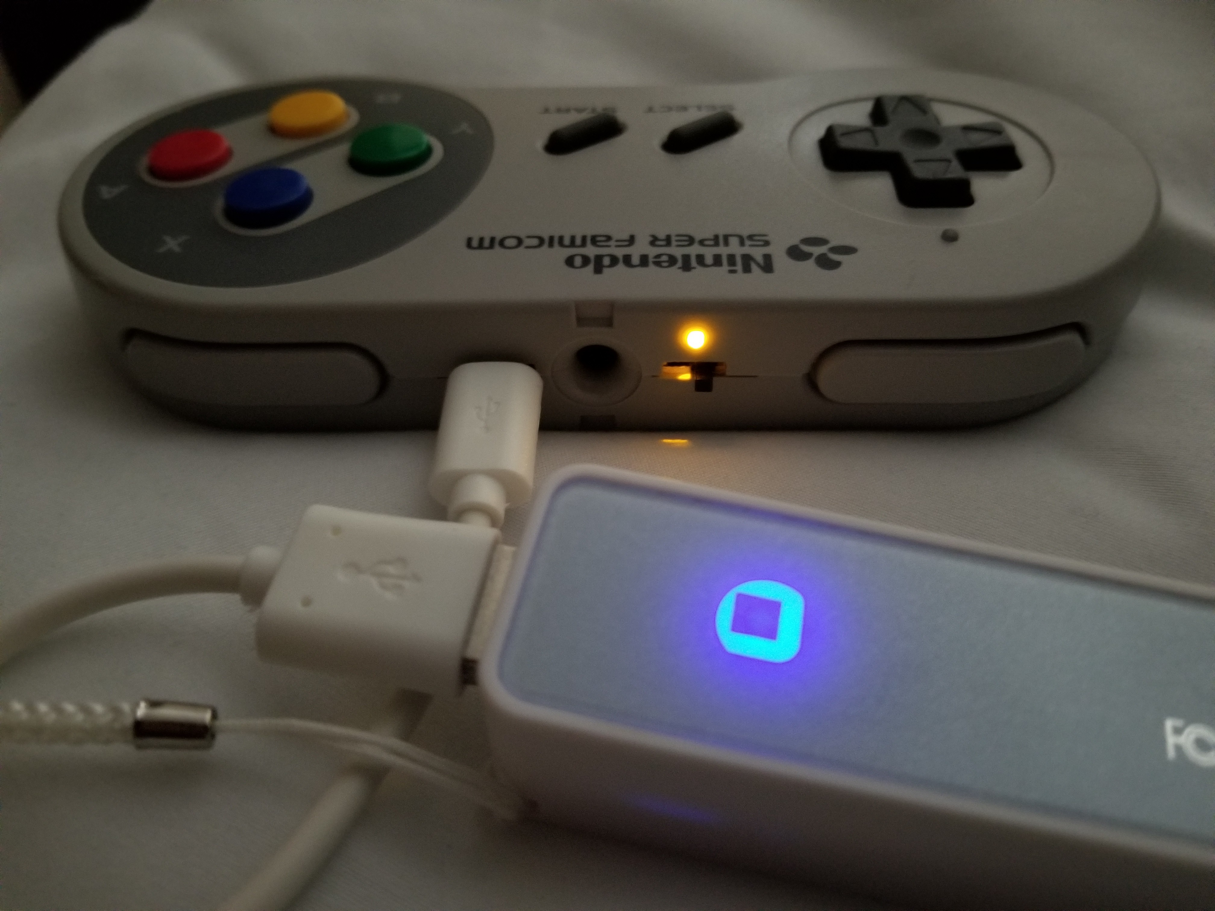
And on the front the multifunction RGB indicator does a great job of notifying status at a glance. I had originally wanted to put a 5mm led in the cable hole at the top but quickly realized it wouldn't be very useful or visible. The RGB indicator flashes purple when in the unpaired/pairing state, and when paired will light up in a solid color to signify the battery level (pwm driven). For instance blue means battery level is high, green is mid, orange is low, and red is very low. I currently just have it on solid and have used it for half an hour with only 0.2-0.3V drop from 4.2V full charge so I expect even burning current on having it constantly lit wont be too detrimental for me. If you want to squeeze more battery life though it would be easy to periodically briefly blink the color as I have updating the led color programmed as a task which is triggered by a counter and flag. The coolest part I think is that both the rgb and charging indicator use light pipes ... but not commercially available ones. I ended up using transparent 1.75mm pla filament. I cut off a stub, lightly heated it with a lighter to allow me to press it to a flat surface to flatten and widen it so it holds itself in place inside the hole and finally sanded the other end smooth so it diffuses the light. Then all that is necessary is to drill a 1/16th hole and dab a tiny bit of glue and you are done.
Another issue I had as there is hardly any space between the shoulder button and the dpad inside the shell and I didn't have any 0603 rgb leds on hand so I ended up soldering tiny 0603 individual red, green, and blue leds in common cathode configuration to fit in the space I had as seen here attached right above the up button on the board.
And here are the tiny boards that are the heart of the transmitter and receiver soldered up and ready to install. Really impressed with how fine the silkscreen in, great job JLCPCB and thanks for them sponsoring a video for this project! Check them out here: $2 PCBs (in 48hours): https://jlcpcb.com
So now that I am done the SNES controller (I may build an accompanying NES version in the future) I just need to pretty up the receiver dongle in the next part of this series.
Update: Ran an extended battery test yesterday for a good 6 hours to check that the RGB indicator works as intended and everything is operating correctly.
Pairing (Purple blinks alternate with measured battery life)
High (Blue) : 4.2>=Vbatt>3.9V
Mid (Green) : 3.9V>=Vbatt>3.6V
Low (Orange/Yellow, looks white in pic I assure you it is not irl) : 3.6V>=Vbatt>3.4V
Very Low (Red) : 3.4V>=Vbatt
So to start this project off thank you bbtinkerer for your original classic joystick project which inspired and started off this project by providing base code for the protocol (https://hackaday.com/2017/05/19/a-diy-nes-advantage-controller-for-the-nes-classic/).
I also made a quick video demoing the prototype controller here and some talk about the prototype board and latency
So a little info, I am using the HC-5/6, as the bluetooth serial communication link which connects the receiver (dongle that plugs into the classic console) and transmitter (controller). Here you can see I hardwired the HC-05 module (after setting up the AT mode to allow master mode and autoconnecting to any other slave module).
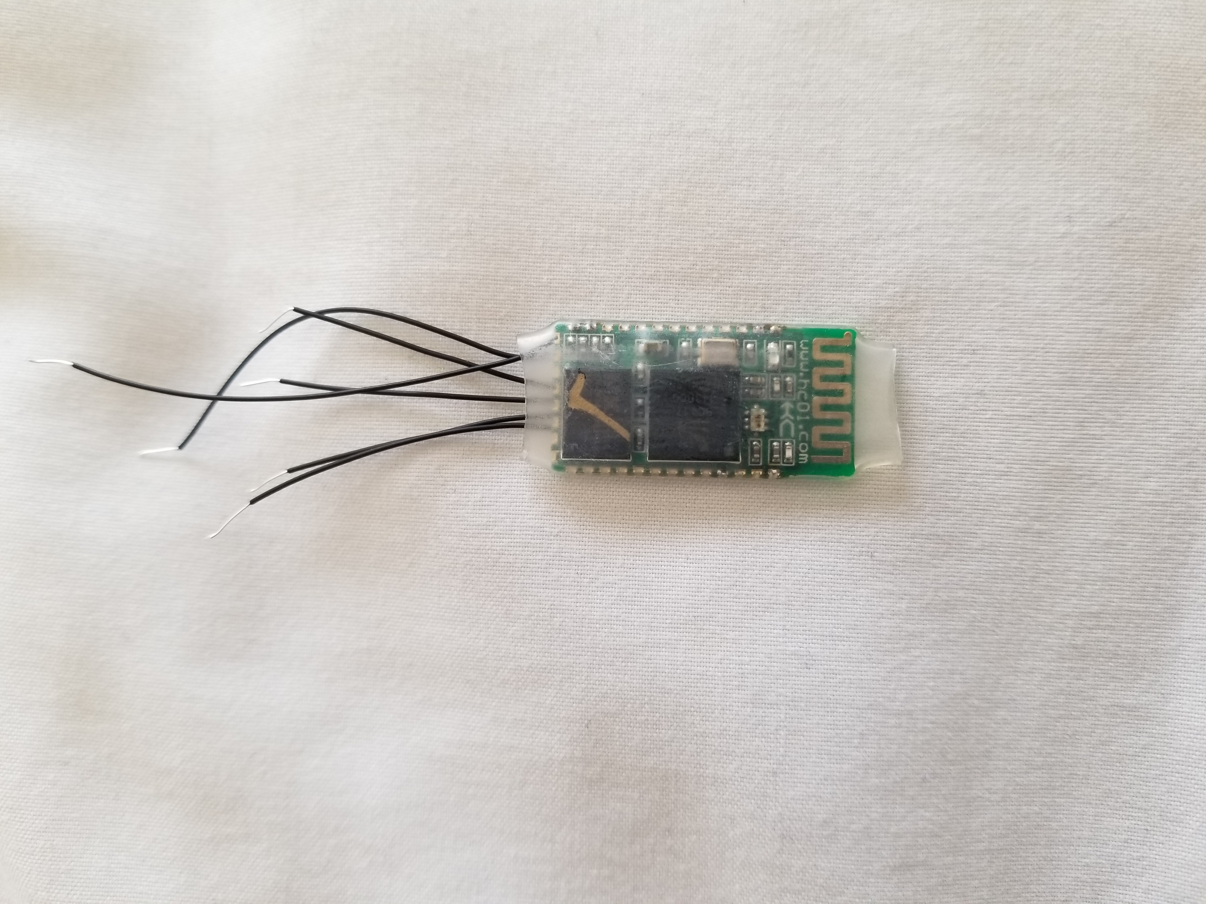 Next up, the software runs on an ATMEGA328P with each the transmitter and receiver having their own controller on tiny little general purpose boards I designed and ordered through my sponsor JLCPCB (thanks a bunch!!!). Check them out here: $2 PCBs (in 48hours): https://jlcpcb.com
The transmitter connects to the original SNES controller board's SPI serial shift register and polls it just like the console would. Once the button states are captured, then they encoded into a 2 byte packet to be sent over the bluetooth UART serial. Here's the transmitter circuit. The HC-05 bluetooth module is on the front and the discrete RGB leds right above the up button. 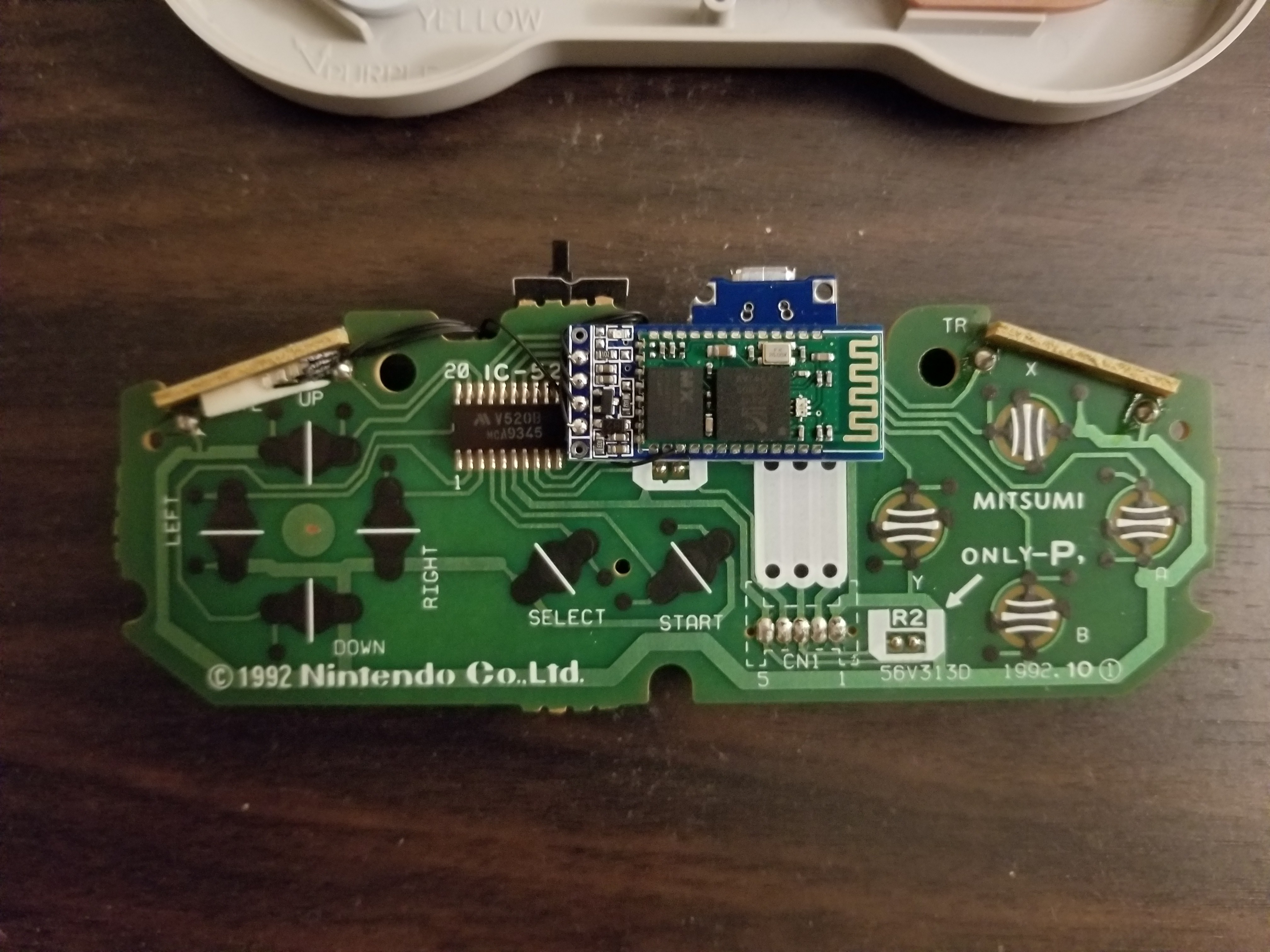 The battery (a 330mAh 3.7V cell) and charging circuit with micro usb are on the back left hand side. The atmega328p and 3.3V LDO regulator are on the right here.
We can see that delta T is just under 30mS which equates to:
Less than 2 frames of latency assuming NTSC 60 frames a second (or equivalently 1 frame for 30 fps). So definitely good enough for me and the majority of the types of games I play (although this might pose problems for games like punchout that require frame perfect button inputs).
In the next part I will add some finishing touches to the controller and button it all up. Then I will finish the receiver and maybe make versions that are compatible with original consoles and usb.
Create an account to leave a comment. Already have an account? Log In.
Thanks, I've used good and bad controllers so I wanted to make something that would actually be useful. The software is fairly generic so it should be fairly easy to port to a number of other micros (and add transmission of extra data like battery voltage, etc). I've posted the usb receiver code but still need to clean and upload the controller code so expect an update with that soon.
Take your time, I'm good with projects for what feels like the next ten years anyways >.>
Become a member to follow this project and never miss any updates
 Rob Smith
 tEEonE

 danjovic
Ahh, doesn't this look fantastic!
I love that you finished up by adding remapp-pability of the keys. That's the part that often sucks with controllers (well, apart from the steam controller ;) )
I'm tempted to make one of these myself now! Though I might be tempted to switch to an ESP-Pico instead of an AVR...
I wonder how useful a small app to monitor the controller would be. It'd be easy whipping something up in Qt to check the battery voltage and set key remapping...