Ken Yap
-
Adding a USB serial interface
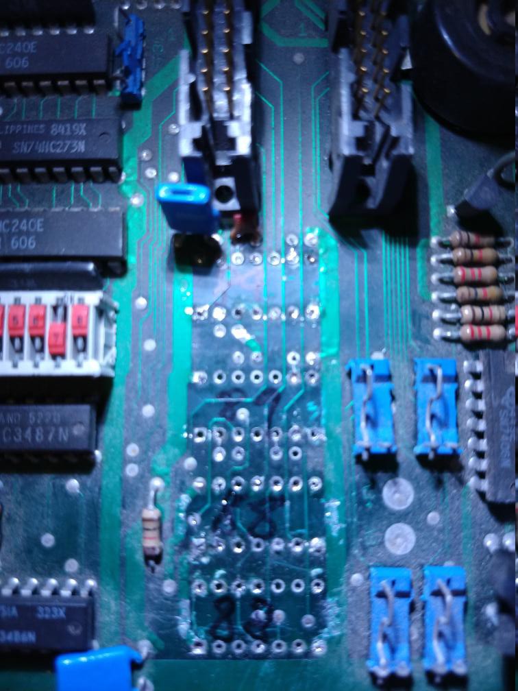
01/13/2019 at 23:34 • 0 commentsI decided to remove the RS-232 interface chips (2 each of 1488 and 1489) and connect a USB serial interface directly to the Z8440 (Z80 SIO/0), avoiding all the malarkey with RS-232 voltage levels. I won't have the hardware handshake signals but these days equipment can keep up with 9600 baud without blinking an eye.
I first used a soldering iron and solder sucker, but that didn't work so well for this two sided board. The next time at work, I got some time on the Hakko vacuum desoldering gun but this hasn't been maintained so the vacuum is weak.
After a moment's hesitation I decide to snip the chips out. I am adverse to destroying working stuff, but I have heaps of RS-232 chips which I'll probably never use up in my lifetime. I still had to remove any pins that broke off the chip package. This is what I ended up with. It isn't pretty but it's ready for the next stage.
![]()
While I was at it I also removed the 7805 voltage regulator and soldered in a connector so that it could be wired up to a 5V power pack.
-
Installing a small ROM monitor
12/26/2018 at 14:52 • 0 commentsI've put this aside for too long. It occurred to me the other day to put a small ROM monitor on board so that I can find out if things are working. Something that will give a prompt, allow me to show and modify registers, memory, and I/O ports. I found the MINOS monitor written in C to be compiled by SDCC, which will make modification easier. I'll have to change the ROM and RAM locations to suit. Also to write I/O routines for the Z8440 SIO, the ones in the original appear to be for the Z8470 DART. The original did some convolutions to fit the code in 2 kB, but I have no such constraint. I'll probably start with a 2764 or a 27128 EPROM giving 8 or 16 kB code space.
With this in mind I needed to find out what the Tx/Rx clock sources for the SIO were. So more tracing with a continuity meter. First thing I found out was the Tx and Rx clocks of both channels were tied together so there was only one clock source. I thought it might come from the CTC, but it turned out to come from a 74HC393 binary counter, which was wired up to divide by 32. The input came from the crystal, running at 4.9562 MHz. Doing the arithmetic shows that this means with the SIO in x16 mode, the baud rate is 9600, with an error of 0.8% as the division is not exact. This is tolerable as up to 2% is allowed for async comms. Still I wonder why they chose 4.9562 MHz for the system clock. Probably a standard crystal frequency.
I'm not going to get the RS232 transceivers working, this would require getting the +/- 8V power lines working, and I'll need a serial port at the computer end. Instead I'll connect one of those USB to TTL level converters that are only a buck or so from eBay. What I'll probably do is remove the RS232 chips and put IC sockets in place in case I want to revert to them. Then I'll solder some headers to connect the appropriate pins of the sockets to the converter. I'll dispense with handshaking and flow control, so I'll only need 3 wires. It should be possible to program the SIO to not require handshaking.
-
Driving strip LEDs
10/22/2018 at 22:32 • 0 commentsJust learnt about very bright strip LEDs in multiple colours you can get from eBay for about 1 USD/metre. They are grouped in 3s, with a current limiting resistor in each group. The bus voltage is 12V. Specs say they draw 4.8W/m which means 400mA. Since there are 20 groups/m this means the LEDs are run at 20mA. Brightness control would be by PWM.
Certainly this is the sort of thing the power transistors on the board can drive. What sort of lighting to make though? Christmas fairy lights? Home disco? (Very retro 😃.)
-
Mapping the I/O space
10/13/2018 at 00:15 • 0 commentsWith a continuity tester I mapped out the I/O space. Besides the address lines, these lines also participate: /M1, /IOR. The devices and the corresponding bits that activate them, from A4 down to A0 are:
74LS138 1 of 8 decoder: 00XXX
Z8440 SIO: 01XXX
Z8430 CTC: 10XXX
The 74LS138 seems to have something to do with the power drive transistors.
-
Mapping the memory space
10/10/2018 at 08:15 • 0 commentsWith a continuity tester, I worked out the decoder logic for the memory space:
ROM: /CS = /MR + /A15
RAM: /CS1 = /MR + A15, CS2 = /CS1 (jumper option 1) or A13 (jumper option 2)
For the ROM, this means that the address space is from 0x0000 to 0x7fff, working in inverted logic since the CS line is negated. The A14 line however needs to be rewired to the CPU for the full 32kB space, currently it's pulled high, which doesn't matter to the existing 2764 EPROM.
For the RAM, this means that the address space is potentially 32kB. For this the bridge has to be moved to the A13 line since the CS2 pin becomes the A13 pin on larger RAM chips. The A14 pin is already wired to the CPU but is a NC pin on the current 8kB RAM.
This means I can write fairly large programs using lots of data (by Z80 standards).
-
How it started
10/10/2018 at 08:01 • 0 commentsI've sent off for some components from eBay for new projects. They take a while to arrive so while I was waiting I looked for something else in my junk box to work on.
It looks like I salvaged these boards from copiers a couple of decades ago. I don't know if they still work, but there's a good chance that they do and the copier was retired for other reasons. Anyway I have lots of replacement chips if anything on the board needs to be fixed.
Based on the inventory I've started thinking about what to do with it:
What I do not want to do with it:
I don't want make a CP/M computer out of it. If I want to be nostalgic about Wordstar. etc. I can run them in an emulator and it will go faster than any real hardware ever did. Besides the memory spaces aren't conducive to modification to run CP/M.
I don't want to make a clock or something that could be done in much less board space with a modern microcontroller.
There are serial interfaces but I don't want to use them in the final product. I much rather make something that is standalone and has no user interaction other than some switches if necessary.
What I might want to do with it:
The presence of power transistors and comparators on board suggests I could make some kind of controller out of it.
I might have to replace the serial I/O chip with a parallel interface chip. To do this I may have to create a daughter board.
So, until I have figured out its purpose, it might stay a work in progress.
Repurposing a Z80 controller board
A failed attempt to put old hardware to use