-
SWR bridge
10/22/2018 at 14:40 • 2 commentsToday I built the SWR bridge on the breadboard, and adapted the arduino sketch to read the FWD and REV voltages on two analog pins.
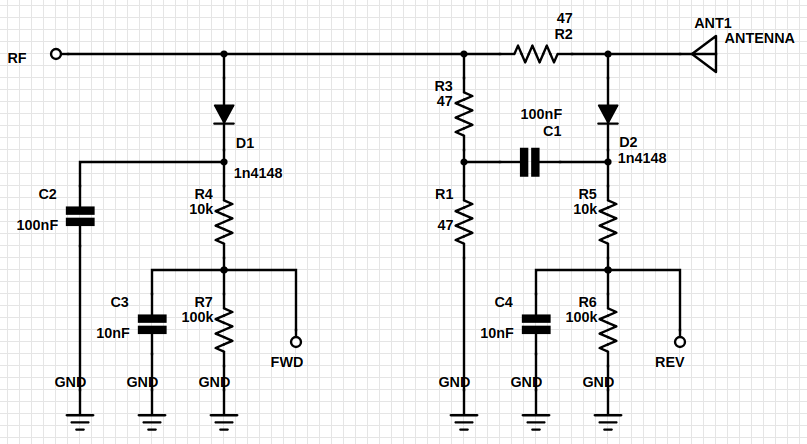
The SWR bridge design is given in the following schema, and taken from an antenna analyzer build by the NJQRP club. A link to the article is given in the links section.
![]()
| chose this design solely because of its simplicity (only resistors, caps and diodes). The analyser in the article also uses an op amp to boost the signal on the FWD and REV ports, and to counter the low impedance on the A/D converter used in their design. In my case the input pins of the arduino have a high enough impedance and the signal should be significant enough to get at least some reading, so in this stage I'm omitting the op amp for simplicity.
The FWD and REV ports are connected to arduino pins A0 and A1 respectively, and the SWR value is calculated using SWR = (FWD+REV) / (FWD-REV).
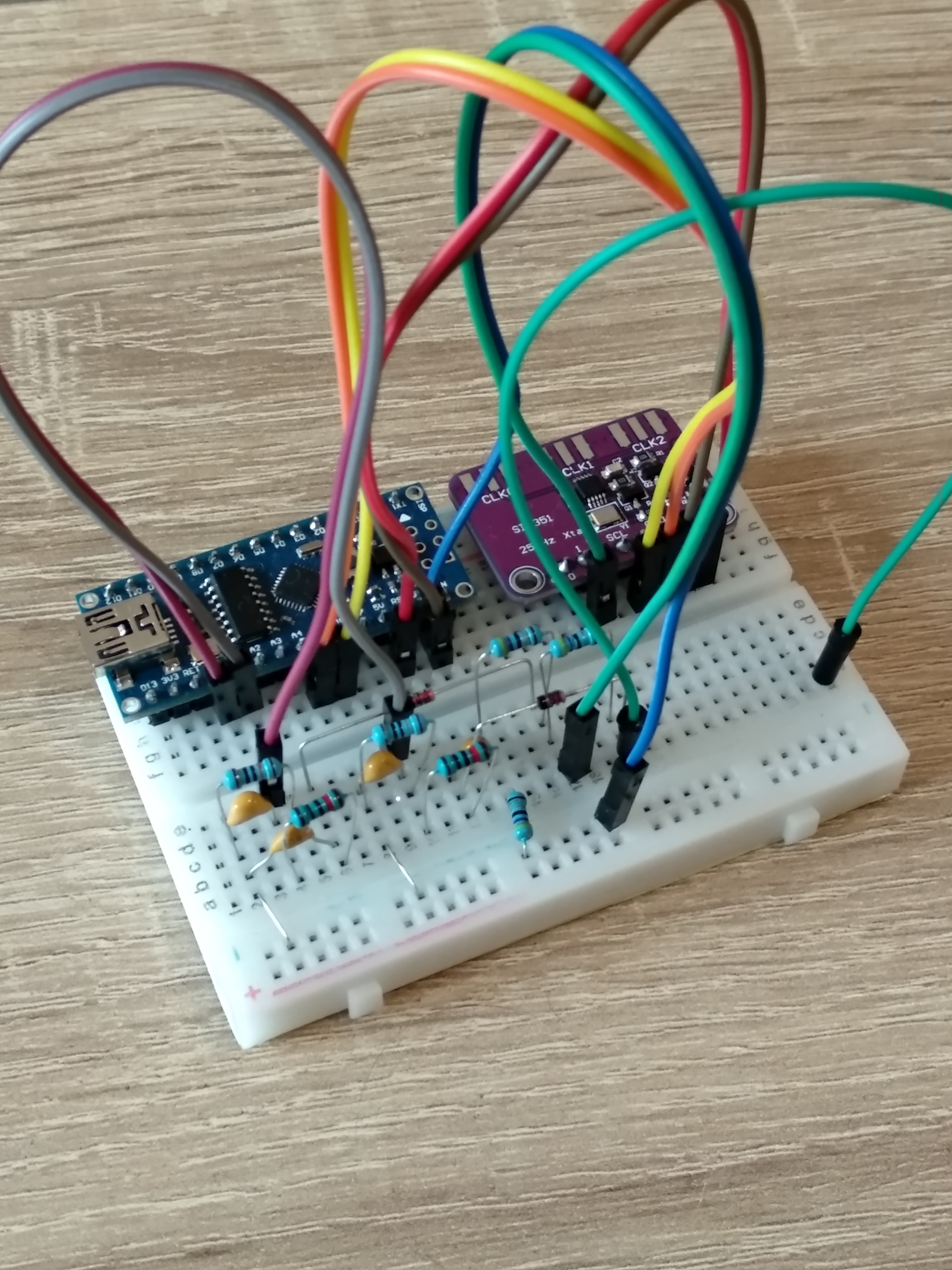
The breadboard with the arduino, si5351 and swr bridge looks like this:
![]()
I know it will give horrible performance on such a board, but i just wanted to see if the concept works.
The swr_sweep.py script is also adapted in the repo, and when i sweep the 27-29MHz range the swr bridge is reporting a standing wave ratio between 3.5:1 and 4:1. Looks promising!
Next i have to find an antenna or so with a known resonance frequency, and test if this little contraption can find the sweet spot.
-
First scripts in repo, frequency sweep working
10/11/2018 at 19:04 • 0 commentsSo the code will live on github, see the link on the project main page.
There are 3 things as of now:
- i2c bus scanner, to see if the si5351 can be found
- a small frequency setting sketch, to see if the library works
- A small sketch (si5351_antenna_analyser.ino) that accepts a new frequency over serial, with an accompanying python script that sweeps between 27 and 29 MHz.
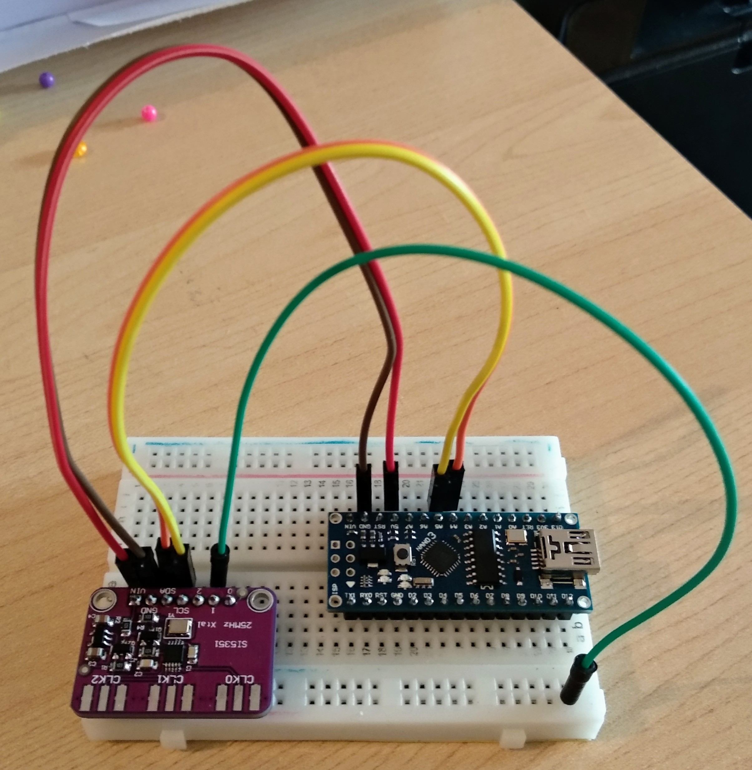
![]()
The wiring is shown in above photo, which is really straightforward. The red/brown pair is power, the yellow/orange pair is i2c, and the green one is connected to clk1 to act as a rudimentary antenna. No passives required anywhere.
So the setup is working now, I can see a nice frequency sweep around 28MHz in GQRX. Next up is the resistive SWR bridge, and the necessary adjustments to the main sketch to push the resulting swr value over serial to the python script.
-
All components arrived, ESP32 not playing ball
10/11/2018 at 11:24 • 0 commentsOver the last month all components arrived, notably an ESP32, arduino nano and of course the Si5351.
Initial testing hit a snag already, since I can't seem to get the Si5351 to work with the ESP32. The tests using the arduino are fine. This might be because the ESP32 is 3v3 and the Arduino 5v, but I don't have any means to test this hypothesis.
For now I'll focus on the arduino, next step is to write some Python to control the clock frequency using the PC, and create a repo on github to keep all the code and test scripts. After that the SWR bridge, which will probably the largest work block for me.
Si5351 HF Antenna Analyzer
HF antenna analyzer using Si5351 as signal source, resistive swr bridge and ESP32 or Arduino as the brains
 biemster

