Beaglebreath
-
Switch over to Arduino
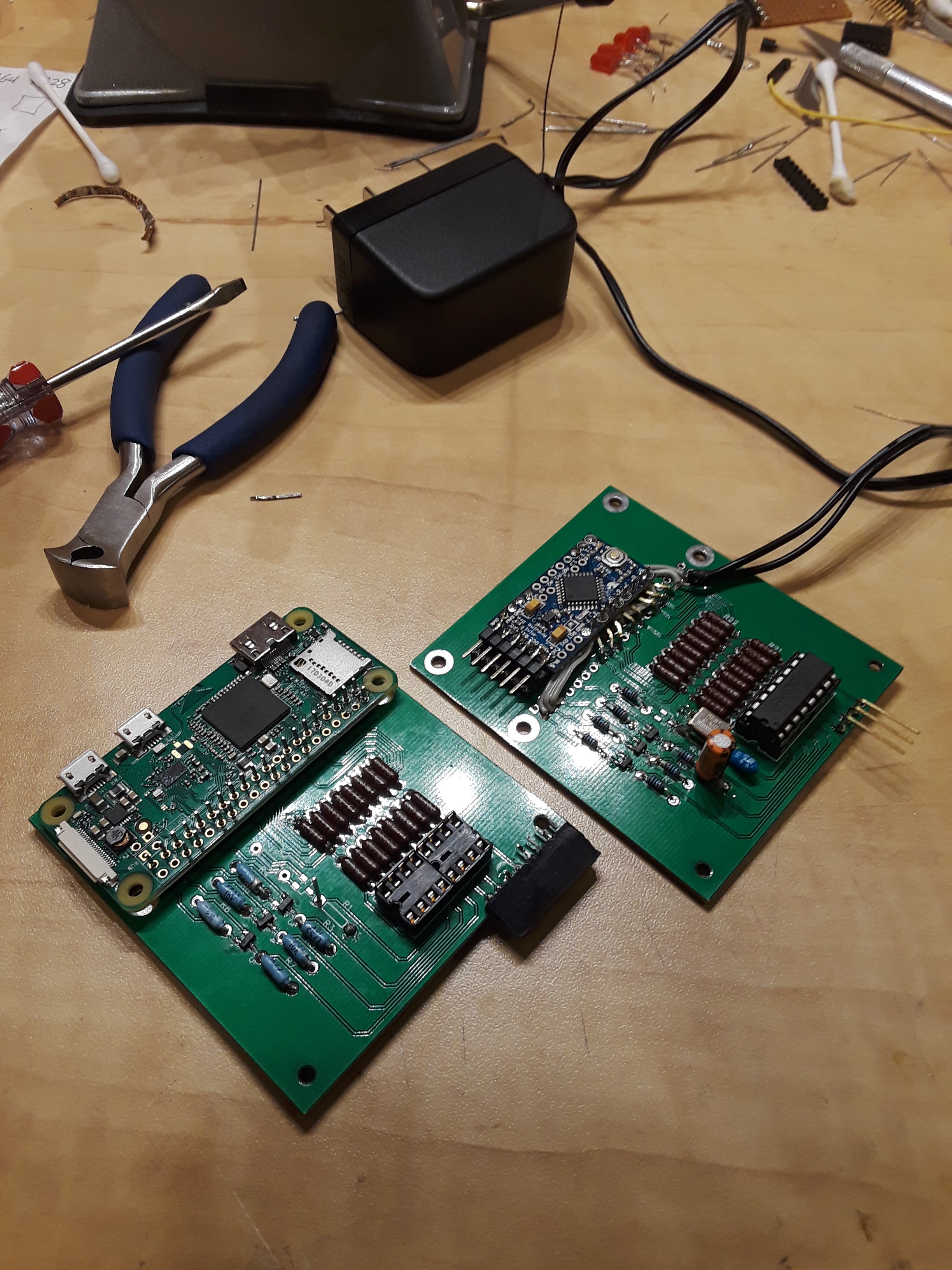
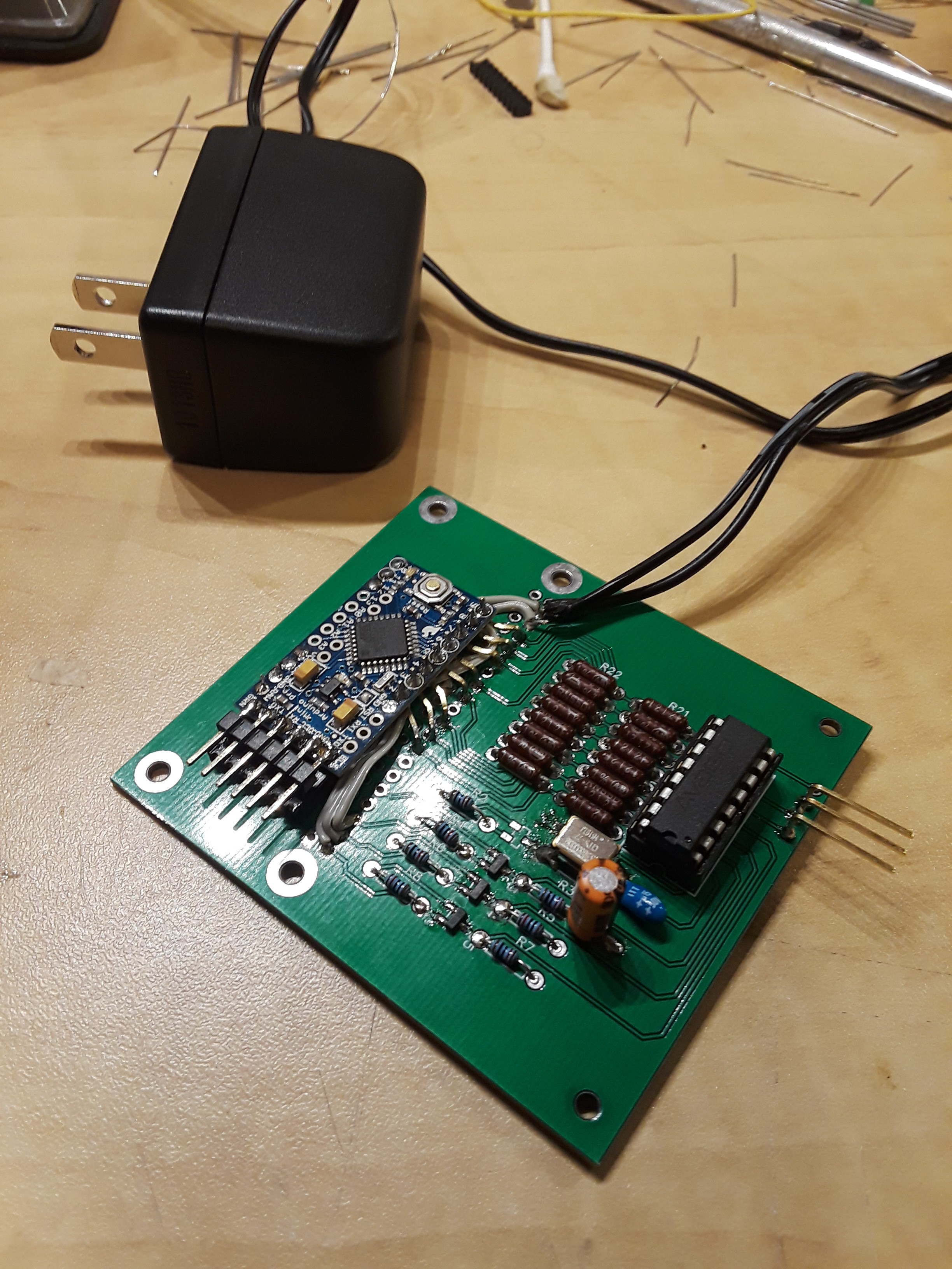
11/12/2018 at 07:49 • 0 commentsEither the on-board power supply of the Raspberry Pi Zero W, does not like my circuit board, or maybe the copper pour on the circuit board is shielding the wifi maintaining reliable connection to my router, either way I got frustrated with the Raspberry Pi and wired in an Arduino Pro-Mini.
![]()
Running the code below and then using the serial monitor, the 16 bit signed integer output of the up down counter of the HTCL-2017.
 int QuadCount; // 32 bit signed integer
 byte HighByte; // 8 bit byte
 byte LowByte;  // 8 bit byte

void setup(){
  Serial.begin(9600);
  Serial.println("start");
  //setup three pins to control HCTL-2017 modes
  pinMode(10, OUTPUT); //SEL
  pinMode(11, OUTPUT); //OE
  pinMode(12, OUTPUT); //RESET
  //setup pins 2-9 as inputs from HCTL-2017 output bus
    for (int i = 2; i < 10; i++)
  {
    pinMode(i, INPUT);
  }
 //RESET HCTL-2017.  Reset counters to zero
  digitalWrite(10, LOW);  //SEL
  digitalWrite(11, LOW);  //OE
  digitalWrite(12, LOW);  //RESET
}
void loop(){
  HighByte = 0;
  LowByte = 0;
  //Stop counting, load high byte onto output pins
  digitalWrite(10, LOW);  //SEL
  digitalWrite(11, LOW);  //OE
  digitalWrite(12, HIGH);  //RESET
  delay(100);
  //read 8-bits from HCTL-2017 high byte.
  for (int i = 0; i < 8; i++)
  {
    if (digitalRead(i+2) == 1) {
      HighByte |= (1<<i);
    }
  }
  //load low byte onto output pins
  digitalWrite(10, HIGH);  //SEL
  digitalWrite(11, LOW);  //OE
  digitalWrite(12, HIGH);  //RESET
  delay(100);
  //read 8-bits from HCTL-2017 low byte.
  for (int i = 0; i < 8; i++)
  {
    if (digitalRead(i+2) == 1) {
      LowByte |= (1<<i);
    }
  }
  //complete inhibit logic reset
  digitalWrite(10, HIGH);  //SEL
  digitalWrite(11, HIGH);  //OE
  digitalWrite(12, HIGH);  //RESET
  delay(100);
  //count for a second
  delay(1000);
  QuadCount = word(HighByte, LowByte);
  Serial.print(QuadCount);
  Serial.print(" ");
  Serial.println(QuadCount, BIN);
}
Took a little bit of tweeking to get it working, but it seems to work just fine.
![]()
-
Circuit Board Power
11/07/2018 at 16:54 • 0 commentsPowered up circuit board by itself to test how much current is needed. The circuit board appears to need 5 mA. I think the Raspberry Pi can supply that...
I have not taken any time to work on code this week so far, but I am wondering about the timing of the control signals between the HCTL-2017 and the Raspberry Pi. I hope I do not need to add some silly time delays in my code.
-
Interfacing Quadrature Decoder to Raspberry Pi
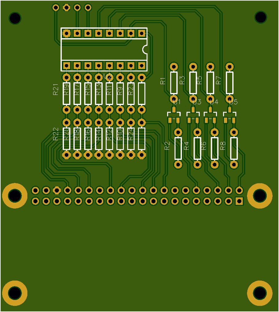
11/05/2018 at 17:35 • 0 commentsLast weekend I downloaded the software needed to design a printed circuit board, and have it appear on a delivery truck at my front door 5-days later. Viola. That was cool. and since this was my first purchase, they threw in all the parts I would need to build this as well. I assembled a circuit board on Friday night and began testing the GPIO outputs which control three transistors, which are doing level shifting from 3.3 volts to 5 volts for the quadrature decoder chip. The three control pins put the quadrature counter chip into one of several modes including; reset to zero, count mode, decode and output high-byte, output low-byte. The decoder chip has a 8-bit parallel data bus for output of the 16-bit counter output. one of the inputs, selects whether the high or low byte appears on the output pins.
![]()
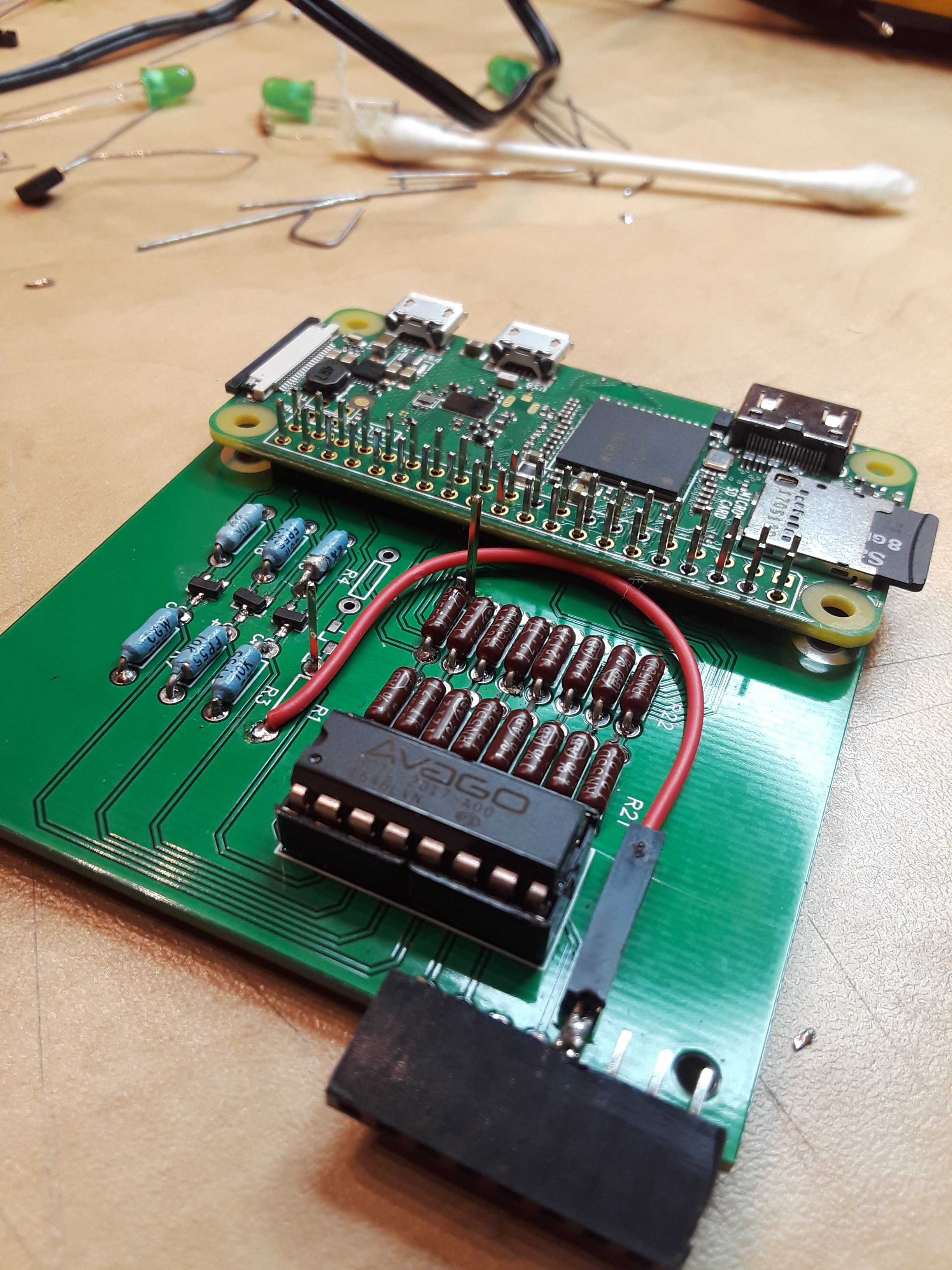
This circuit board reads the REF and MEAS signals from the interferometer. Those two signals are mixed in the quadrature counter, and a count of the number of times the signals wander in and out of phase appear as a 16-bit signed integer on the GPIO of the Raspberry Pi.
My python program is very simple.
- I'm using the ref_index library to determine the wavelength of my laser light
- the wavelength is dependent on the vacuum wavelength of my laser, and how the atmosphere manipulates the wavelength.
- a BME-280 humidity, temperature and barometric pressure sensor acts as my miniature weather station for the interferometer.
- Edlen's Equation is used to figure out how much the wavelength changed.
- The GPIO is used to control the HCTL-2017 quadrature decoder.
- the output of the decoder chip is the difference in wavelengths that the two light paths follow in the optics, relative to a starting position.
- Finally, the counter output is multiplied by the apparent wavelength of the laser light.
The output from the program is distance the moveable mirror moved. The units of measure are the same as the units used for the vacuum wavelength.
import ref_index

import Adafruit_BME280
import RPi.GPIO as GPIO

data_pins = [14, 15, 18, 23, 24, 25, 8, 7]
ctrl_pins = [16, 20, 21]
ctrl_seqs = [1, 1, 1, 2, 2, 2, 3, 3, 3]

GPIO.setmode(GPIO.BCM)
GPIO.setup(data_pins, GPIO.IN)
GPIO.(crtl_pins, GPIO.OUT)

sensor = BME280(t_mode=BME280_OSAMPLE_8, p_mode=BME280_OSAMPLE_8,  h_mode=BME280_OSAMPLE_8)

quadrature_count = 0
for ctrl_seq in ctrl_seqs:
     GPIO.output(ctrl_pins, [(ctrl_seq >> i) % 2 for i in range(0, 3)])
for i in range(0, 8):
     quadrature_count += GPIO.input(data_pins[i]) << i+8
GPIO.output(ctrl_pins, 5)
for i in range(0, 8):
     quadrature_count += GPIO.input(data_pins[i]) << i

temperature = sensor.read_temperature()
pressure = sensor.read_pressure()
humidity = sensor.read_humidity()
wavelength = ref_index.edlen(wave=632.6, t=temperature, p=pressure, rh=humidity)

distance = wavelength * quadrature_count
print(distance)
The decoder chip needs a clock input signal. To get this guy off the ground I'm using a 13 MHz clock generator IC, which plugs into the female connector on the printed circuit board.
As of this morning, I have the circuit board able to be powered up, and the GPIO controls are working. The 13 MHz clock is working too. I have pulled the quadrature counter out of it's socket and jumpered in, some bits into the input data bus, to let the code operate on those values.
To finish this circuit board;
- I need to clean up the codes associated with ctrl_pins in the python code above.
- wire in the REF and MEAS signals,
- I need to make sure I'm not killing the little power supply in the Raspberry Pi.
- I will have this accomplished in the next night or two.
To conclude, I'm happy to see that the circuit I designed is apparently going to be able to do what I wanted. I think I will have it wired to the interferometer today or tomorrow. However, while playing with the REF and MEAS signals and watching them carefully on my oscilloscope, It looks like the HP 5508A Measurement Display of the original interferometer, counts 1/6th of each wavelength of the quadrature signals. So that means that the design of my circuit board will only give me a fraction of the resolution I am seeking. I think my resolution is going to be on the order of ±50 ppm of an inch.
To skin this cat, I'm planning to add a set of Phased Locked Loops to the REF and MEAS signals. The PLL's will be used to multiply the frequency and phase of the two signals to a higher value, so that the phase count will have a higher resolution. While I'm designing PLL circuits, I figured, I'd use a third one to generate a clock frequency which will be derived from the laser's REF frequency. This way the clock will be in phase with the REF signal, and all of them will be derived from mixed laser frequencies.
- I'm using the ref_index library to determine the wavelength of my laser light
-
Frequency Counters
10/29/2018 at 18:14 • 0 commentsA couple days ago, I took a dual channel Oscilloscope and hooked up Channel 1 to the Laser's REF output signal. That gave me a picture of a square-waveish signal that was about 2.1 MHz. I then hooked up Channel 2 to the MEAS signal on the Optical Receiver. This too, was producing a 2.1 MHz signal.
I setup the movable Retroreflector, so that it would wiggle a few 10's of millions of an inch on it's mounting screws. (This was because I had not setup the alignment of the Retroreflector at it's remote location). As I moved the Retroreflector back and forth, I could watch a corresponding apparent phase shift between the two signals. The relative change in phase, in terms of direction and speed, corresponded with my moving the Retroreflector by hand.
My suspicion is, that each 360° phase shift cooresponds to a 25 µinch movement of the Retroreflector. The apparent phase shift is due to the shrinking and stretching of the MEAS signal due to a Doppler shift when the Retroreflector moves. For each 360° phase change, one whole count is changed on the accumulated MEAS counts as compared to the REF counts. When there is no relative motion, the REF and MEAS return to the same frequency, and there is no additional change in the relative frequency counts.
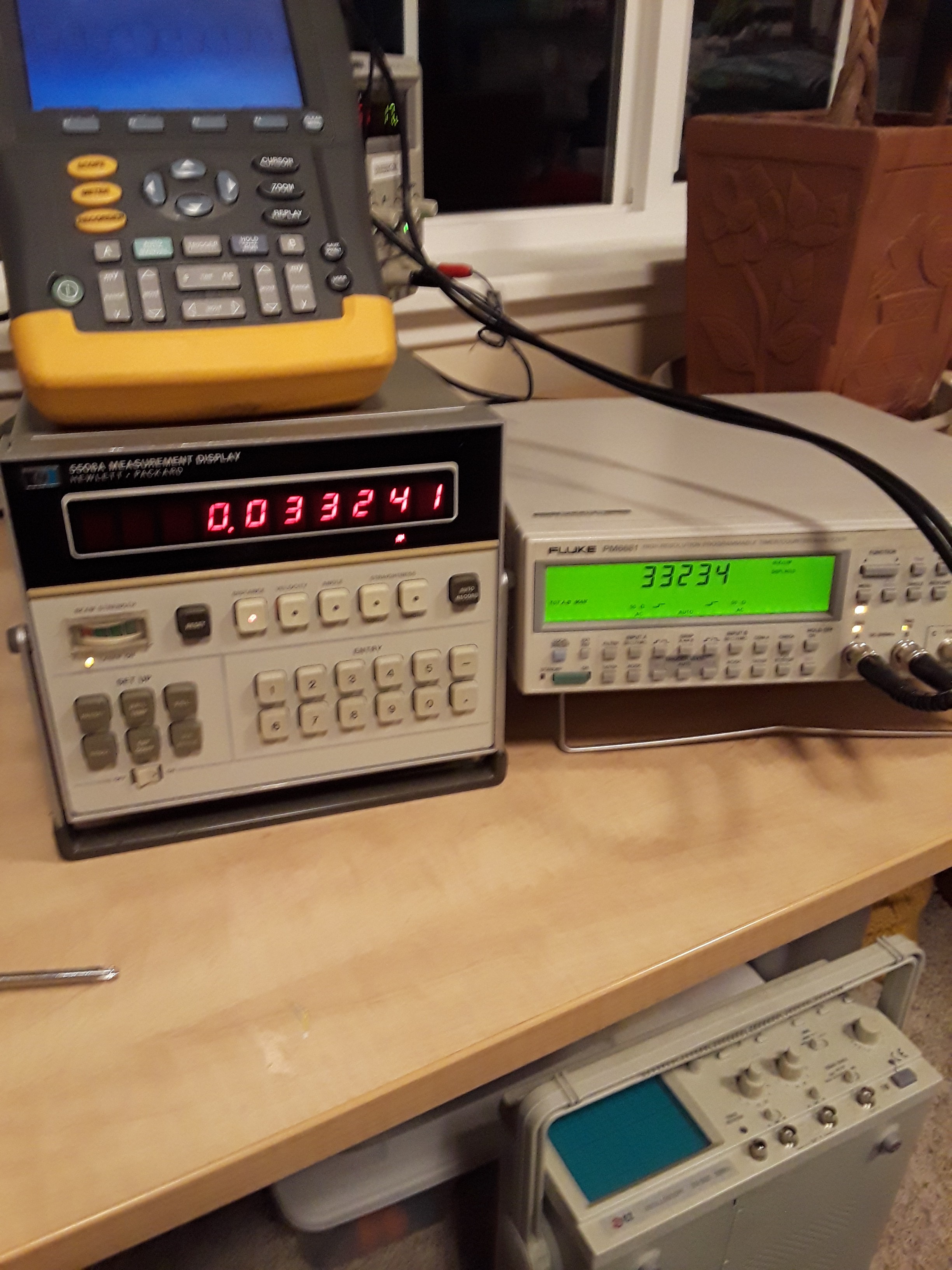
After playing with the scope, I tried hooking the REF and MEAS to a Fluke PM6681 Dual channel Frequency Counter/Analyzer. After setting up the input loading and thresholds I got a reliable count of the waves from each channel.
The Frequency Counter has many modes to choose from to help analyze the signals. I put the Frequency Counter into it's A-B Counter Mode. In this mode, the Frequency Counter counts the waves that trigger the counter and displays the difference of the two counts on it's front display.
At that point I had a number that would change as the number on the output of the Interferometer Display changed. Both values would increase and decrease in time with regard to each other.
Next I activated the MATH functions of the PM6681. I applied a linear equation to the A-B output. This allowed me to scale the output to match the Interferometer display. The MATH function also allows an easy way to reset to Counters to 0.
That was fun :) I got the scale factor close enough to have a mostly precise agreement between the two instruments.
![]()
Next I began trying to think of a scheme to make a Raspberry Pi or a micrcontroller to the work that the instruments are doing. I decided that I did not want a Raspberry Pi spending it's life watching the inputs and counting waves. It had more important things to do...
I spent several days batting around in the wilderness, reading scholarly documents about phase-detection, and other things when I came across a video by Ben Krasnow on Youtube, (His Video). His video was about a fiber optic joystick, but he was using a decoder chip which caught my attention. And that lead me to discover the Avago HCTL-2017 .
This is a CMOS IC, which has a quadrature decoder, up/down counter, and 8/16-bit output modes. This guy can clock up to 33 MHz too. I then ordered a few and had them in hand last week. Spent some quality time with the breadboard, and got the HCTL-2017 wired up to the Raspberry Pi. I wrote some Python scripts to control the GPIO, that was being used to control and read from the IC.
By Friday night, I had a short Python Script controlling the HCTL-2017. I was reading noise from the inputs, since I was too scared to connect the interferometer to the breadboard.
I began designing a printed circuit board to replace the breadboard circuit. This is what I ended up with. It was ordered on Saturday. I'm now waiting with baited breath for it to arrive.
![]()
-
Weekend Fabricating
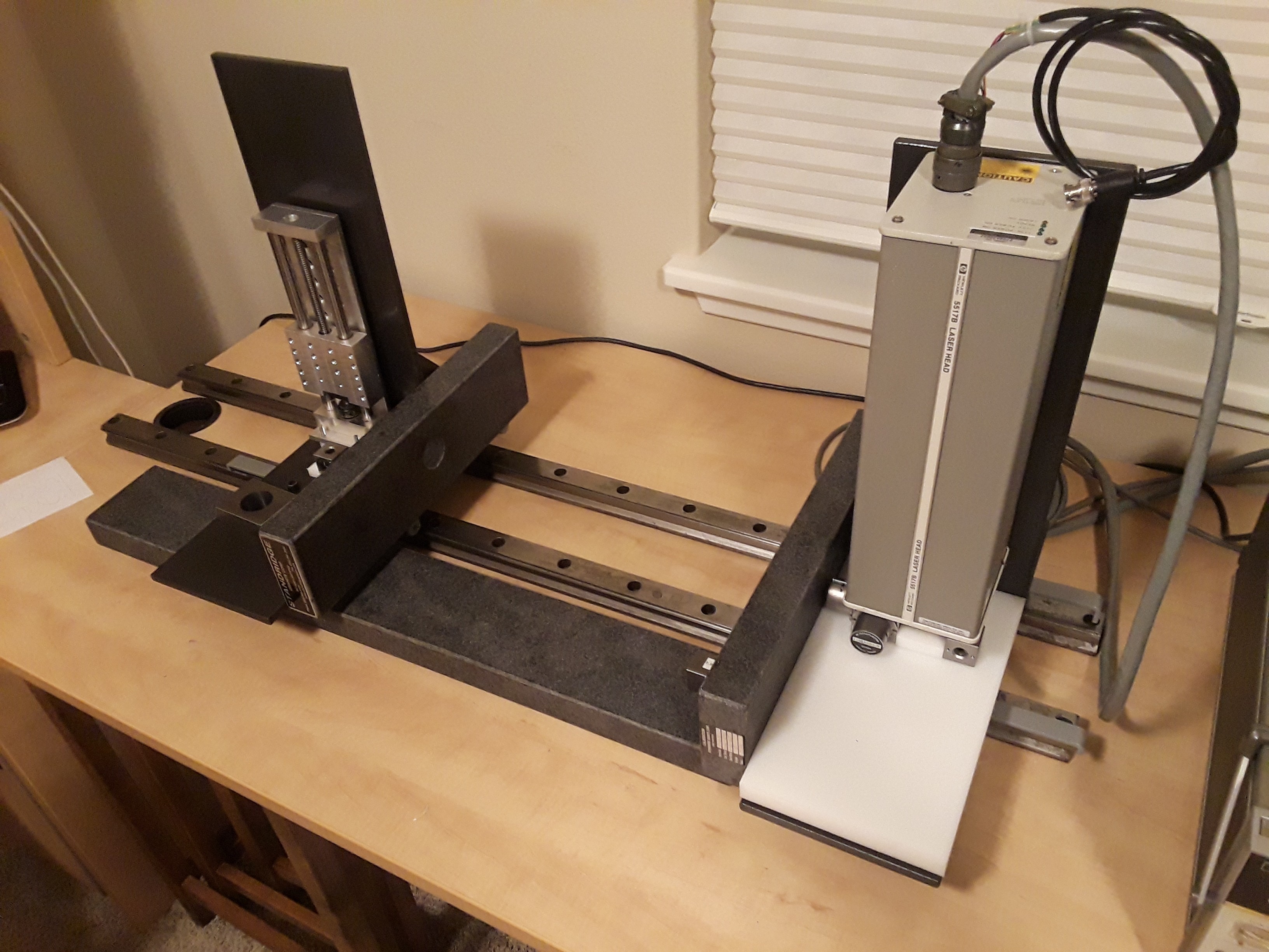
10/22/2018 at 18:03 • 0 commentsHere is a picture of all the granite pieces placed where they'll eventually be used.
Spent the week end trying to mount the optical components onto a piece of HDPE. Most of the optical pieces are now mounted, but I need to correct a misalignment now.
![]()
-
Optics
10/18/2018 at 16:48 • 0 comments![]()
(sorry for the spelling error in the picture above...)
The picture above is my arrangement of the optical parts of this project. All parts remain stationary, with respect to each other, except for the Retroreflector shown at the bottom of the picture. The relative motion of the retroreflector toward or away from the interferometer will cause a Doppler shift in the reflected light frequency.
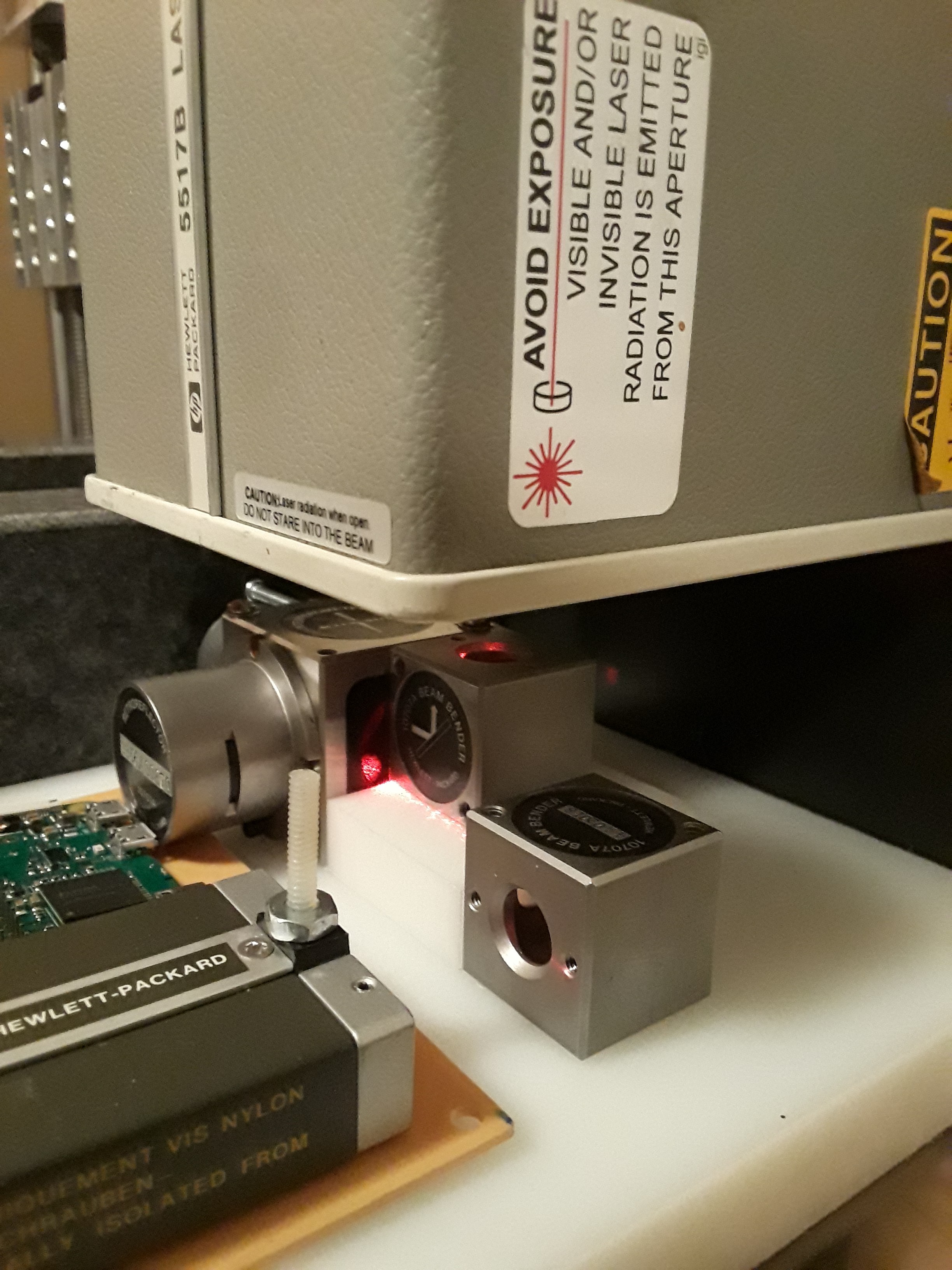
Light enters the optics from a Laser. The laser is a HP 5517B, which is magical. The laser light emitted is comprised of two slightly different frequencies, and are deliberately shifted out of phase by 90°. As I have been playing with the laser from time to time, I realized that the two frequencies and a 90° phase shift is what is needed for radio heterodyne circuits as well as radio mixer circuits.
The HP 5517B laser uses the Zeeman Effect to generate the two frequencies. The Zeeman Effect is a result of slightly different energy levels that are available for electrons associated with the Helium and Neon gasses in the laser. An internal magnetic field is used in the laser to affect the electron and their Electron Spin property. The Electron Spin also magically generates separate polarities of the light depending on the Spin orientation.
The HP 5517B also houses an internal optical receiver. The internal optical reciever detects the two light frequencies/polarities and mixes them to produce an electrical signal which is provided on a connector on the rear of the laser housing. This signal is a TTL level square(ish) wave at about 2.145 MHz. This wave is not effected by the external optics and/or any motion of the optics. This signal will serve as a REFERENCE signal in a mixer circuit or a quadrature encoder circuit.
The light from the laser has two polarities, shifted by 90°. The remaining optical components are polarized so that they can manipulate the polarized light.
- One of the polarities is directed into the optical interferometer, and is reflected onto a stationary retroreflector. The light is reflected from the retroreflector back into the interferometer, which then directs the light toward the external optical receiver. This polarized light path passes through optics that are stationary and therefore do not have a Doppler shift.
- The other polarity is able to pass through the interferometer without being manipulated in any way. The light proceeds to the movable retroreflector. The retroreflector sends the light ray back in the direction it arrived from. Again the light passes through the interferometer and follows the same path as the other polarity on to the optical receiver.
![]()
The two polarized light beams arrive at the optical receiver. (if I understand correctly) the beams are each shifted 45°, so that they share the same polarity and can finally mix together. The optical mixing is analogous to mixing radio frequencies. A sum of the two frequencies is produced (and ignored) and a difference frequency is produced. The difference frequency is related to the 2.145 MHz REFERENCE that I mentioned earlier.
- If the moveable mirror is not moving; then the mixed light frequencies produce a difference frequency equal to the REFERENCE.
- if the movable mirror is moving, then the mixed difference frequency will be equal to the (REFERENCE ± Doppler Shift). The receiver produces an electrical signal from it's connector with it's own TTL level square(ish) wave. This signal is refered to as MEAS.
Rethinking the Luminiferous Aether Detector
recent projects with quadrature encoders have inspired to look at this old project.