repkid
-
Slow progress
11/02/2016 at 16:46 • 0 commentsThe progress has been rather slow this past week due to exams. Anyway, after some research I came to the conclusion that: the RPZ can't toggle its IO pins from within Processing fast enough to drive the EPD, writing an entire E-book software package is a tad ambitious and an ARM controller makes a decent alpha prototype driver for the EPD.
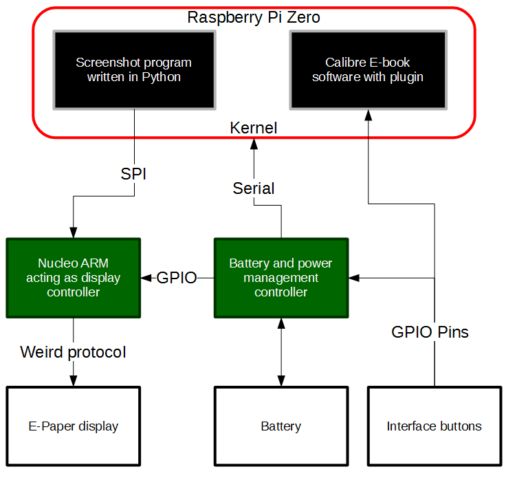
To present this visually this is now the new plan:
![]()
Let's break this down shall we?
The screenshot program on the RPZ basically takes a screenshot with python-webkit2png, then it reads the .png, applies a filter to convert to black and white (for now) and then sends this over SPI to the display controller.
The display controller shall be programmed in C because this is a language I am good with and basically pushes the incoming SPI data to the screen in the WP (weird protocol). The GPIO connection from the power management controller is basically a shutdown/low power mode command.
The power management controller keeps an eye on battery levels and sends a shutdown command over serial to the RPZ when the user turns the device of or the battery levels are low. This will be using an Arduino for now but the final product will use a more low power microcontroller. After all, it doesn't need to be powerful.
The interface buttons consist of a power switch, forward and backward switches and menu navigation switches. Nothing exciting.
The star of the show is Calibre, an all-in e-book package, we'll just be using the e-book viewer. Because the interface isn't what I want (too many colours and buttons that rely on a mouse/touchscreen input) I am going to write a plugin (also Python) that accepts GPIO inputs and simplifies the display. In case I can't get Calibre to accept GPIO inputs I will write another program to run on the RPZ that converts GPIO inputs to key presses, and Calibre will simply respond to these "hotkeys".
All of the programs on the RPZ will be started with a daemon so that restarting the device automatically opens them.
-
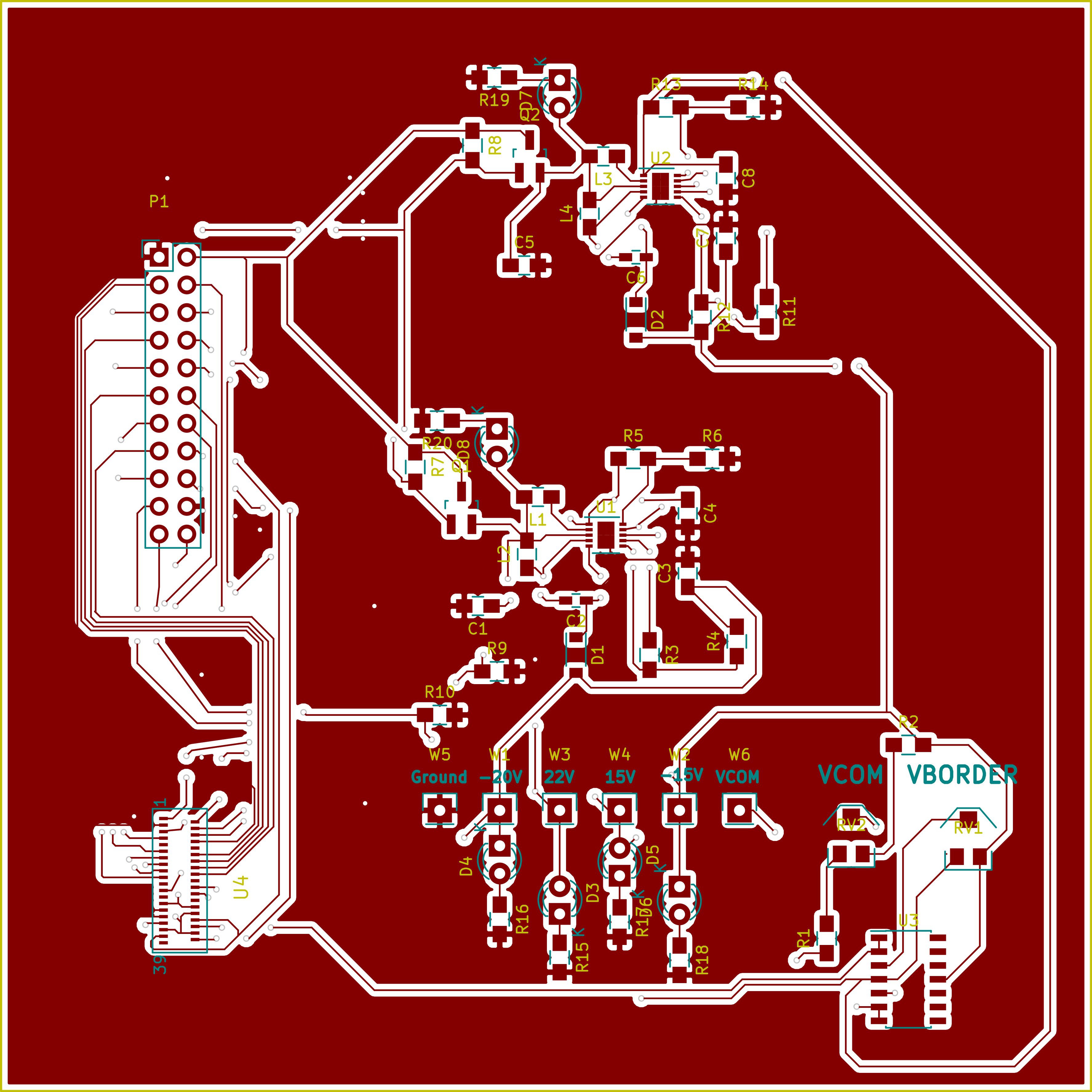
PCB now fab house ready
10/15/2016 at 11:34 • 0 commentsThicker traces are generally better, also a design stays less cluttered if you start of with a distributed ground plane. I've also added indicator leds because they generally make life easier by a wide margin.
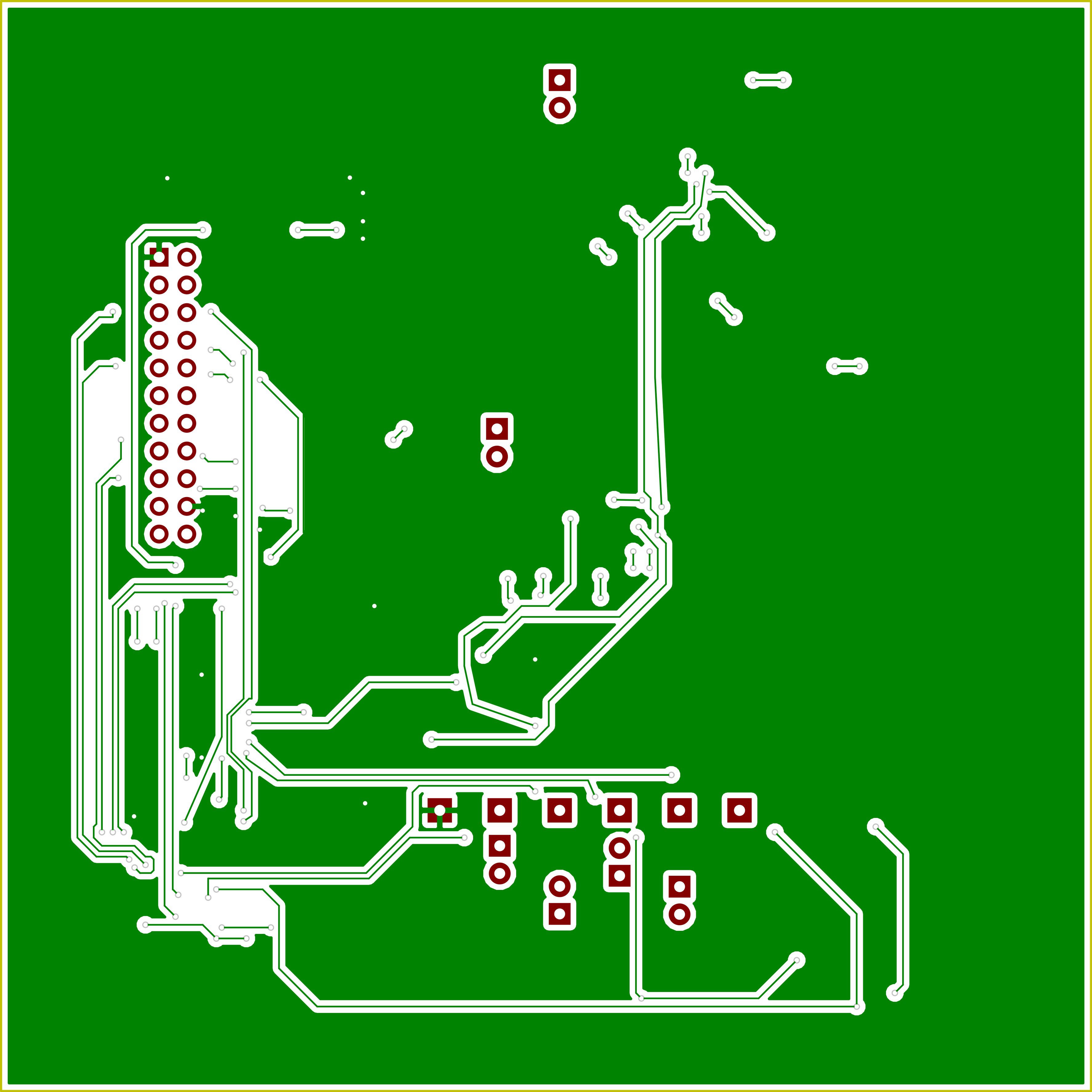
Front:
![]() Back:
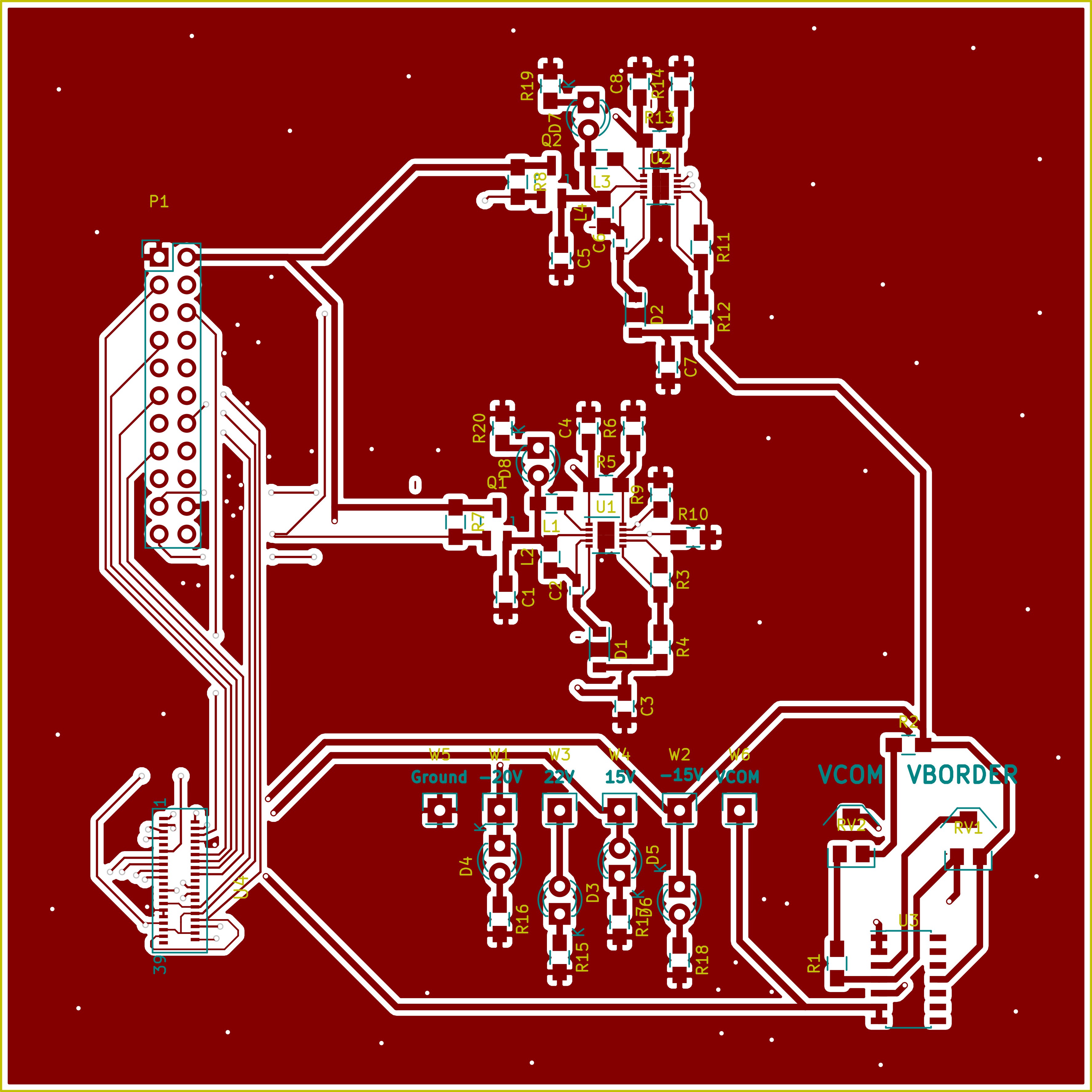
Back:![]()
-
PCBs first draft
10/13/2016 at 00:01 • 0 commentsI know these look pretty terrible and space optimisation could be better. But, this could work I think. I will still need to do a version 2, this draft was more to get knowledgeable with Pcbnew than it was to create something to send to a fab house.
Front:
![]() Back:
Back:![]()
-
Finished the schematic
10/11/2016 at 13:06 • 0 commentsThe title's pretty self-explanatory. Turns out KiCad is pretty intuitive to use. This is the schematic for the board that will act as the interface between the RPZ and the EPD. Next I'm going to create the PCB design. Should be up in one or two days. And the source files for this magnificent schematic will be uploaded once I clean things up a bit.
![]()
-
A new day, a new software: KiCad
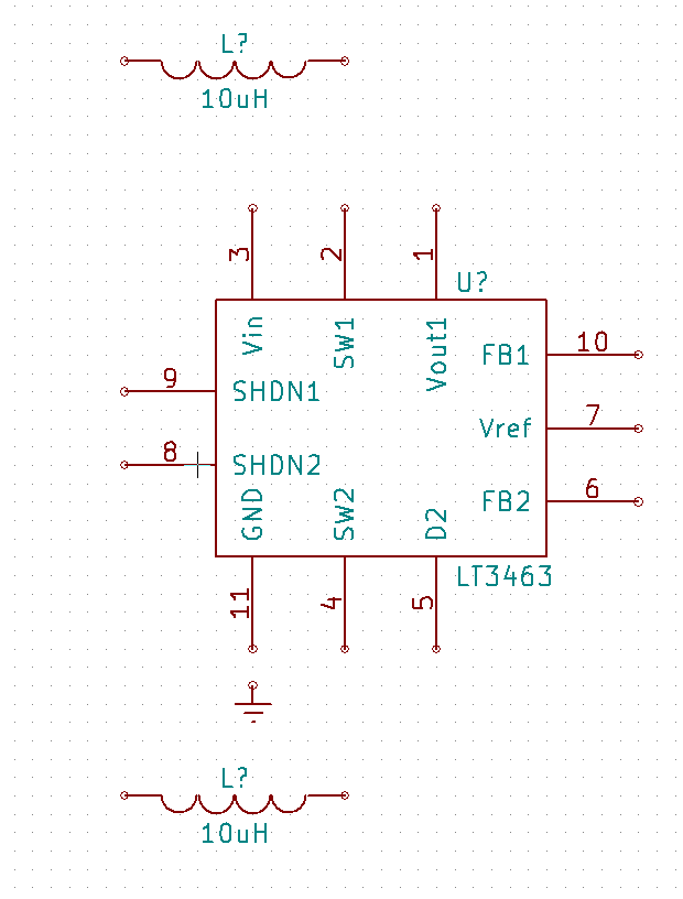
10/10/2016 at 21:39 • 0 comments![]()
I plan to provide the positive and negative voltages needed for the EPD with two LT3463 chips. But KiCad doesn't have it in its libraries. It does have the LT3472 which has the same package meaning only the pinout needs to be edited.
Himnull - A Raspberry Pi E-Reader
Making an open source e-reader for less than $75.
 Back:
Back:
 Back:
Back: