-
Battery Performance
12/31/2019 at 19:11 • 0 commentsI did some testing to see how long the unit can operate on a fully charged 3000mAh LiPo battery.
Before this testing the MicroPython code was tuned to optimize the runtime on battery power:
- The particulate sensor is turned off until a measurement is needed. The datasheet specifies that the sensor needs to be powered on for 30 seconds before accurate measurements can be realized. To meet this requirement, the sensor runs for 30 seconds every 15 minute logging period. The particulate sensor subsystem current is significant, around 180mA.
- The WiFi radio is turned on only when measurements are pushed to a cloud database with MQTT (every 15 minutes). Turning off the radio reduces current by about 40mA.
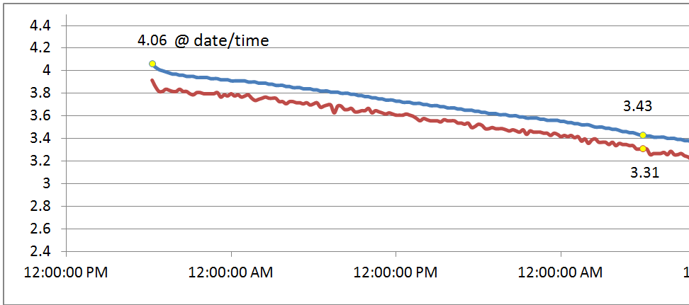
Starting with a fully charged battery, voltage is logged every 15 minutes to a SD Card file. Here is the profile of the battery voltage versus time. Blue is the average voltage, Red is the minimum voltage over the 15 minutes log period. I chose 3.3V as the battery voltage level that marks the end of the test.
Runtime: 41 hours
The standalone runtime of 41 hours exceeds the initial requirements of 8 hours standalone runtime.
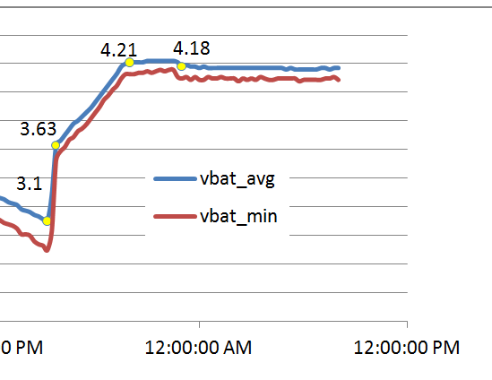
Next, I measured the recharge performance. When the battery voltage was 3.1V I powered the unit with a 5V wall adapter. Similar to the discharge test, average and minimum battery voltages are recorded to SD Card every 15 minutes.
The LiPo battery is recharged using the TP4054 Li-Ion battery charger component that is built into the Lolin D32 Pro module. The plot below shows that the battery charger quickly ramps up the charge to 3.63 V and then a slower ramp-up to 4.21V over a period of 4.25 hours. A constant voltage of 4.21V is applied for 3.0 hours. The drop in voltage to 4.18V is a clue indicating that the charging is complete.
Recharge time = 7.5 hours
-
Measuring Audible Noise in Real-Time
11/11/2019 at 15:32 • 0 commentsThe idea of including real-time decibel measurement in this project started as a stretch goal. Audio samples are already continuously written to a WAV file on an external SD Card. The plan is to analyse these recorded audio samples at a later time. But, it would be a lot more interesting if the Street Sense unit could show a real-time value of the audible noise on the local display. There are two challenges I faced:
- Calculate a decibel measurement without stealing away too many processing resources such as CPU cycles and RAM.
- What algorithm to use?
Like all technical endeavors I started with a Google search: "ESP32 noise measurement". On top of the search results is an Arduino project. That looked hopeful as I can often adapt these type of projects into MicroPython. But, two lines down I hit the jackpot. Here is a project that "checks all of the boxes"
Decibel Meter- yes. ESP32-yes. I2S-yesThe ESP-I2S-SLM Hackaday project provides all the resources on implementing a real-time decibel meter using an ESP32 microcontroller and an I2S microphone. The author, Ivan Kostoski, does an excellent job describing the digital filters that are needed to make an accurate decibel reading from microphone audio samples. The project also shares working C++ code to implement the infinite impulse response (IIR) filters needed in the dB(A) calculation.
Much gratitude to Ivan Kostoski for publishing this work !
The Street Sense project is based on MicroPython not C++ so I reworked the C++ code into a MicroPython C module that calculates dBA. The MicroPython/C implementation is here: MicroPython dBA module in github.
In the Street Sense MicroPython code the dBA calculation is included in the microphone co-routine, in a loop that is used to read audio samples from the I2S microphone and stream the samples to a SD Card. The dBA module calculates dBA incrementally, 256 audio samples at a time. When one second of samples has been processed the final dBA calculation is returned. Performance is excellent. Each incremental calculation of 256 samples takes about 0.25ms and the final calculation takes about 0.6ms. The loop that contains the dBA calculation has constraints based on the 10kHz sample frequency used. The constraint is 25.6ms - on average the loop cannot run longer than this amount of time. So, the dBA calculation only uses 1%-2% of this time allowance.
In stress tests, I found that it is possible to make a continuous dBA calculation while sampling the I2S microphone at 44.1kHz.
I chose to implement the IIR filter and RMS arithmetic using 32-bit floating point precision. The calculations seemed to yield accurate and stable results.
Moving onto some hardware and testing results ...
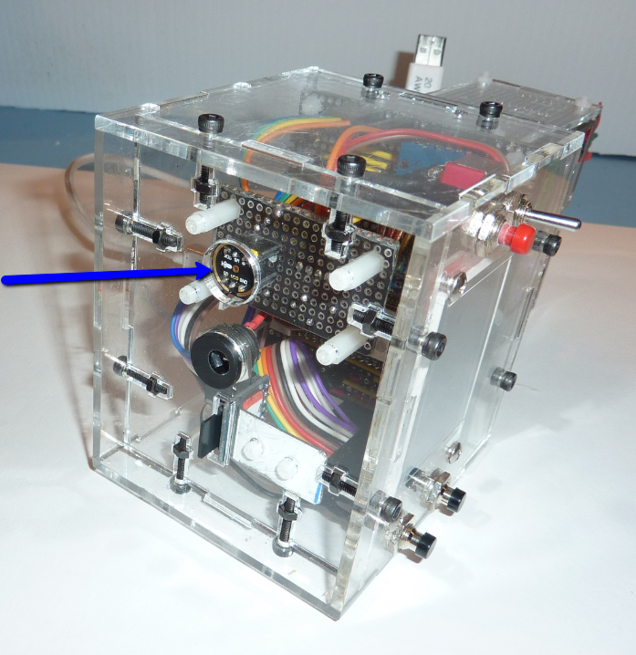
The I2S microphone is located on the bottom of the prototype case, shown by the blue arrow in the photo below.
Test Setup
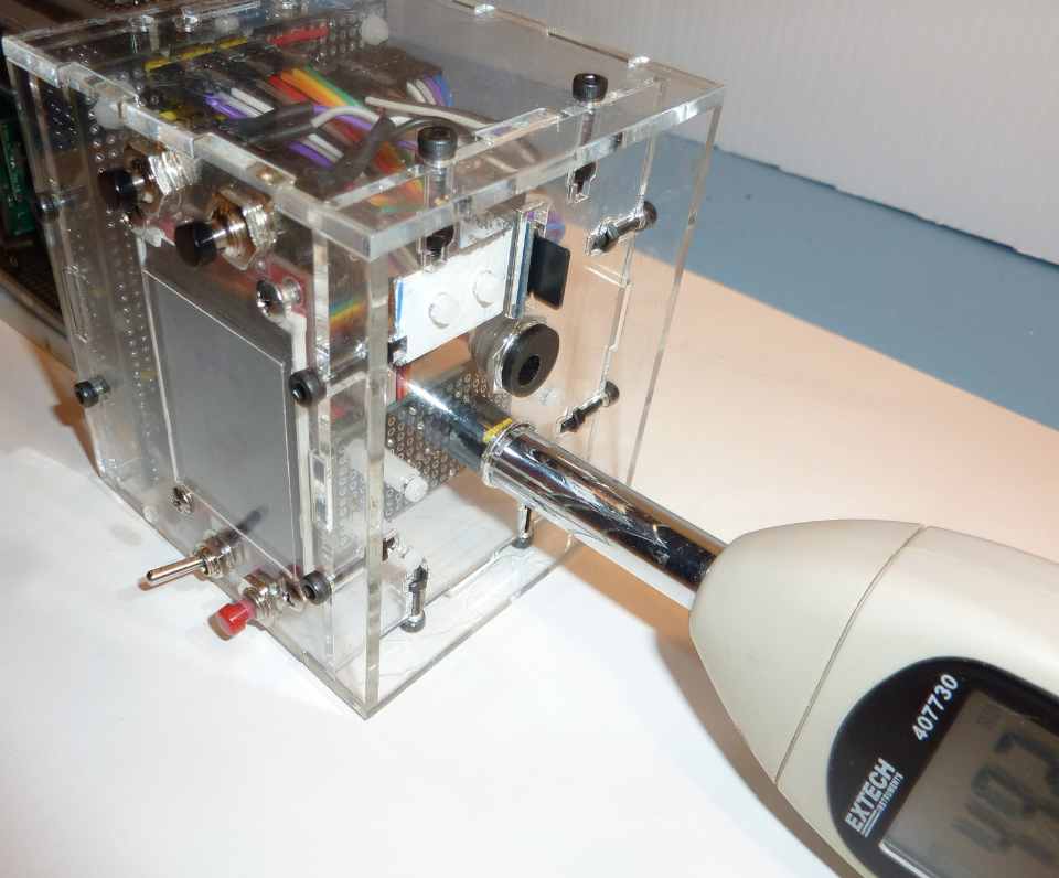
An Extech digital sound level meter is used as the "golden measurement reference". The datasheet of the Extech device indicates an accuracy of +-2dB. The metal wand of the sound meter is placed into the microphone cut-out, almost touching the I2S microphone. With this arrangement both devices receive the same sounds.
An online tone generation tool is used to create pure tone frequencies. The tones are played through a pair of PC speakers.
Test Results
Using the littleVGL graphics library I made a dedicated graphics display that updates the decibel measurement every second. The short video below shows the decibel meter feature being tested with 3 pure audio tones: 500 Hz, 1000 Hz, and 3000 Hz. Note: even though the generated tones were perceived as close in volume by the human ear, the recording camera gives extra emphasis to the final 3000 Hz tone (i.e. recommend to turn down your speakers for this tone)
The video shows that the Street Sense decibel meter prototype follows the Extech meter readings fairly closely, typically within 1 dBA. These results exceed my expectations. The INMP441 MEMS microphone used in this project indicates an accuracy of +-3dB. Perhaps I got lucky and both the I2S microphone and the Extech device are operating the same end of the accuracy spectrum (and making the prototype look more accurate than it really is?)
This result gives me confidence that the Street Sense decibel meter can be trusted.
Integrating the dBA measurement
The real-time dBA measurement gets used 3 ways:
- shown on the TFT display
- published to the Adafruit IO cloud database using WiFI+MQTT protocol
- recorded to SD Card
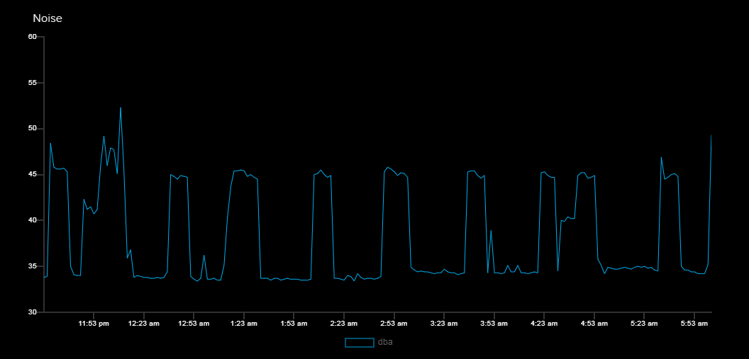
The photo below is a dashboard capture from Adafruit IO showing dBA measurements taken in our kitchen during the night. The time-span is about 8 hrs and shows the sounds coming from the kitchen refrigerator as it cycles on and off.
Scream meter
The unit also proved to be a competent "scream meter" with one family member claiming the top scream at 119 dBA :)
Revisiting problems with the SPH0645LM4H microphone
In an earlier project log I described the problems using a SPH0645LM4H microphone with the ESP32. This microphone is used in the popular Adafruit I2S microphone breakout board. In the project log I show how every audio sample is left shifted by one bit.
I wondered how the dBA calculations would be affected by this L shift.
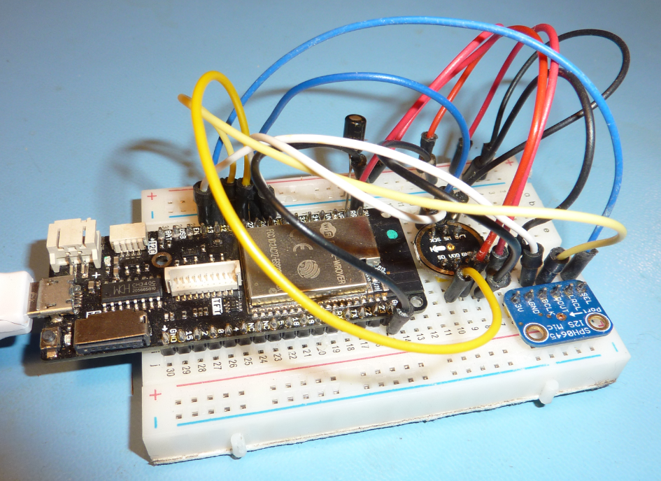
I used two I2S breakout boards (INMP441 and SPH0645LM4H ) and wired them to an ESP32 (Lolin D32 Pro) and modified some MicroPython code to simultaneously read audio samples from both I2S devices and calculate dBA. The ESP32 has two I2S peripherals.
The results are interesting... and expected. Here is one result from both microphones.
INMP441 result = 73.0 dBA
SPH0645 result = 79.5 dBAThe SPH0645LM4H microphone on the Adafruit breakout board consistently delivers a 6dB higher result than the INMP441 microphone.
This makes sense. A single bit L shift in the SPH0645LM4H audio samples is a doubling of value. And a doubling of sample values results in a 6dB increase in sound level value.
If you use the SPH0645LM4H for decibel calculations it is best to shift samples R by one bit before performing the dBA calculation.
-
Farewell Loboris, Hello LittlevGL
10/26/2019 at 02:30 • 5 commentsWhen I started this project the most capable version of MicroPython on the ESP32 device was found in the Loboris port. It was an easy decision to build the Street Sense project on top of this version.
A year later the situation has changed. The Loboris port has remained stagnant for over a year. On the other hand the mainline of MicroPython has advanced significantly and now provides the ESP32 feature set that is needed for this project. I decided to move back to the mainline.
But, one key feature is still missing from the mainline version: good support for a graphical display like the ILI9341 which is used in this project. Loboris built outstanding graphic support in his port. I considered porting his work, but it is a very unique implementation and involves some re-write of the ESP-IDF SPI drivers. Not a good choice for porting.
In February 2019 a Hackaday post announced that the LittlevGLgraphics library had been ported to MicroPython. I had never heard of LittlevGL before then. I made note of the blog post and revisited it in September 2019 when I started hunting for a replacement graphics library. LittlevGL has more than enough graphics support for my needs so I decided to attempt an integration with my project.
The integration of LittlevGL into MicroPython is quite well described. Big thank you to the developer Amir Gonnen who figured out how to bind LittlevGL objects into MicroPython. Quite amazing and innovative work. I'm humbled by these great programmers who are able to realize these advances in design. Here's one thing I can say about GUI design in MicroPython: It rocks. You can iterate so quickly. I'll guess 5x faster with LittlevGL-MicroPython than compiled C.
Most of the integration work involved modification of the MicroPython Makefile. If you would like to make a similar integration into your MicroPython project my GitHub commit might save you some time.
It was all going smoothly until I started seeing problems with SD Card operation that would happen immediately after the LittlevGL library was initialized. In the Street Sense design, the ILI9341 display and external SD Card share the same SPI bus. Perhaps a bad idea, but I ran out of ESP32 gpio pins and had to economize. Without getting into details, this turned out to be a big problem to solve. It took about a week to figure out and even called for some oscilloscope work on more than one occasion. In the end I found a way to make it work, but don't fully understand why it works. Usually I dig deeper to understand why, but I'm so worn out by this problem I just want to move on. The solution: run the LittlegVL SPI bus in full-duplex mode. For some reason this allows the graphics library to play nice with the SD Card on the SPI bus. Again, I don't know why.
Some stats on the LittlevGL addition to MicroPython. Without any feature pruning it blew out the ROM partition of MicroPython with the ESP32 continually resetting after being flashed with the firmware. The graphics library has a configuration file that allows features to be turned on and off. With a small effort I was able to make LittlevGL fit into MicroPython.
The result:
- ROM (flash memory): about 156kB
- Time to display a 320x240 pixel image: 120ms (ESP32 running at 240MHz, SPI bus at 20MHz)
There is likely a lot more that can be removed to save flash space, but it's not really important to find these efficiencies at this point.
To wrap up this project update: Street Sense is back on the mainline of MicroPython and has great graphics support for the display using the LittlevGL library.
Lastly. A big shout out to Boris Lovosevic for leading the way on the ESP32 port of MicroPython. Your work has helped many. An outstanding developer.
-
Laser Cut Enclosure
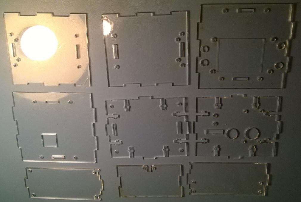
09/23/2019 at 20:19 • 0 commentsThe next step involved designing a laser cut enclosure for mounting all the PCBs and all other electronic components. 3mm clear extruded acrylic is used for the first version of the enclosure.
Design in Fusion 360
Fusion 360 was used to design the acrylic panels that are assembled into an enclosure. I've used Fusion 360 for some simple design projects, but nothing this complex. It was a steep learning curve, aided by a few excellent YouTube tutorials, for example:
Learn Fusion 360 or Die Trying LESSON 3: Understanding Constraints
Fusion 360: How to Export as DXF FileThe enclosure is composed of 2 main sections:
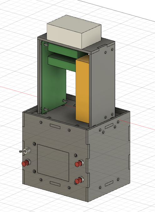
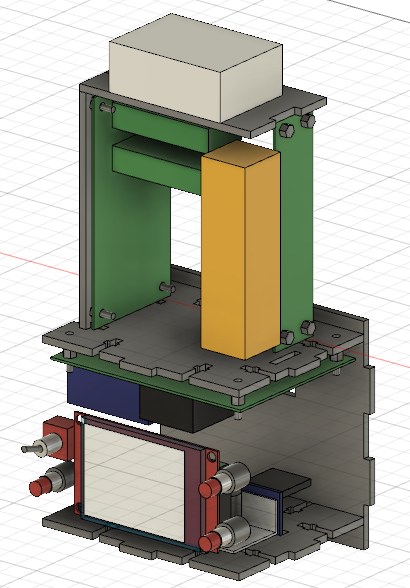
- Three acrylic panels that carry the sensor PCBs and will fit inside the Accurite vented enclosure
- Six acrylic panels that carry the CPU PCB and components for the user interface, such as the display and buttons.
The 3 KiCad designed PCBs were exported as DXF files so that the standoff mounting holes could be pulled into Fusion 360.
Here are a couple of screenshots of the enclosure in Fusion 360
A browser viewable version of the Fusion 360 design is here
Laser Cutting
The 3mm acrylic sheet was cut on a 50W laser cutter at Victoria Makerspace
"Days to design, minutes to cut" - the laser cutting time was trivial, maybe 20 minutes.
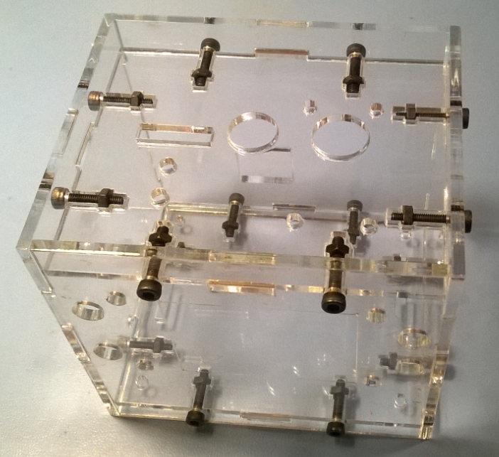
A T-slot technique is used to connect the panels
Assembly
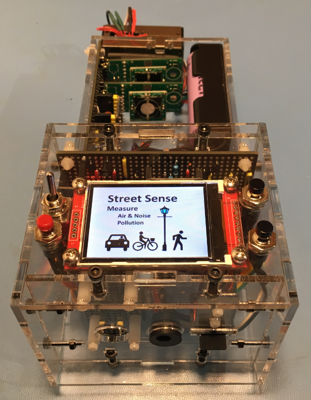
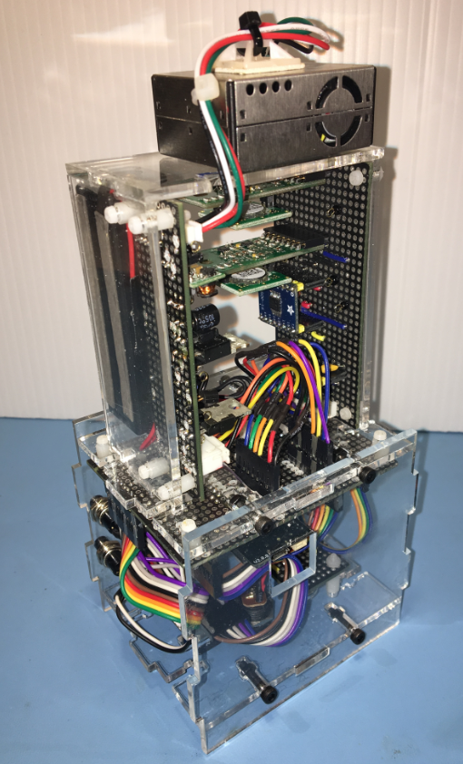
Final assembly, with PCBs and components mounted to the acrylic panels. The front face has the display, on/off, reset, and two buttons for the user interface
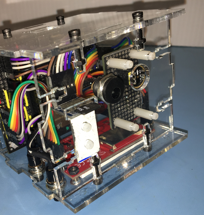
On the bottom is the SD Card slot, jack for DC power, and opening for the I2S microphone (seen below, left to right)
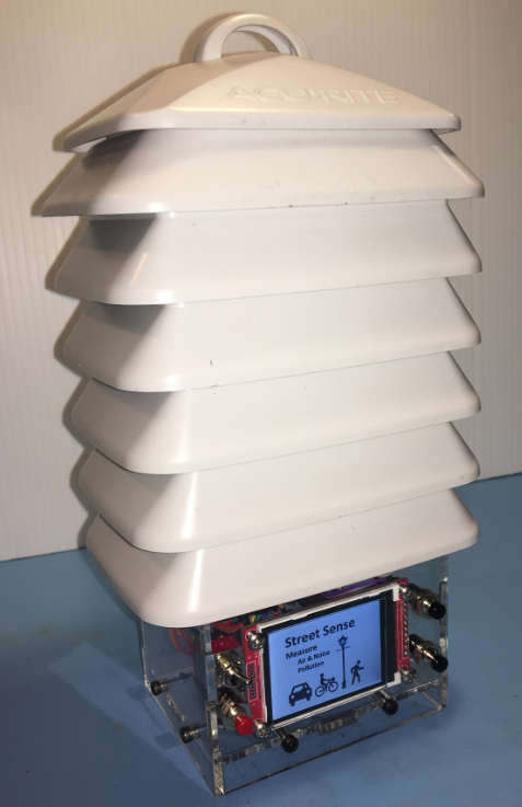
The T-slot approach allows the side panels of the cube section to be removed. This facilitates taking measurements on the CPU PCB. The top section shows the Ozone and NO2 Spec Sensor modules, mounted downwards so dust does not fall onto the active sensing surface.Finally, a view with the sensor section installed inside the Accurite weather shield
-
A Slimmer Power Conditioning Module
09/13/2019 at 15:02 • 0 commentsI decided to redo the power conditioning PCB module. For these reasons:
- Make a slimmer version that will allow space for the LiPo battery to fit inside the vented enclosure
- Add 4 mounting holes for standoffs
- Add more test points and jumpers to facilitate voltage and current measurements
- Get more experience using KiCad for Stripboard layouts
Using KiCad, it was straightforward to iterate the stripboard layout to reduce the PCB width by about 25%. This task would have been more difficult and time consuming using hand layout methods
The first version of the power conditioning module is described in an earlier project log
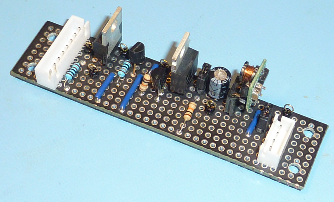
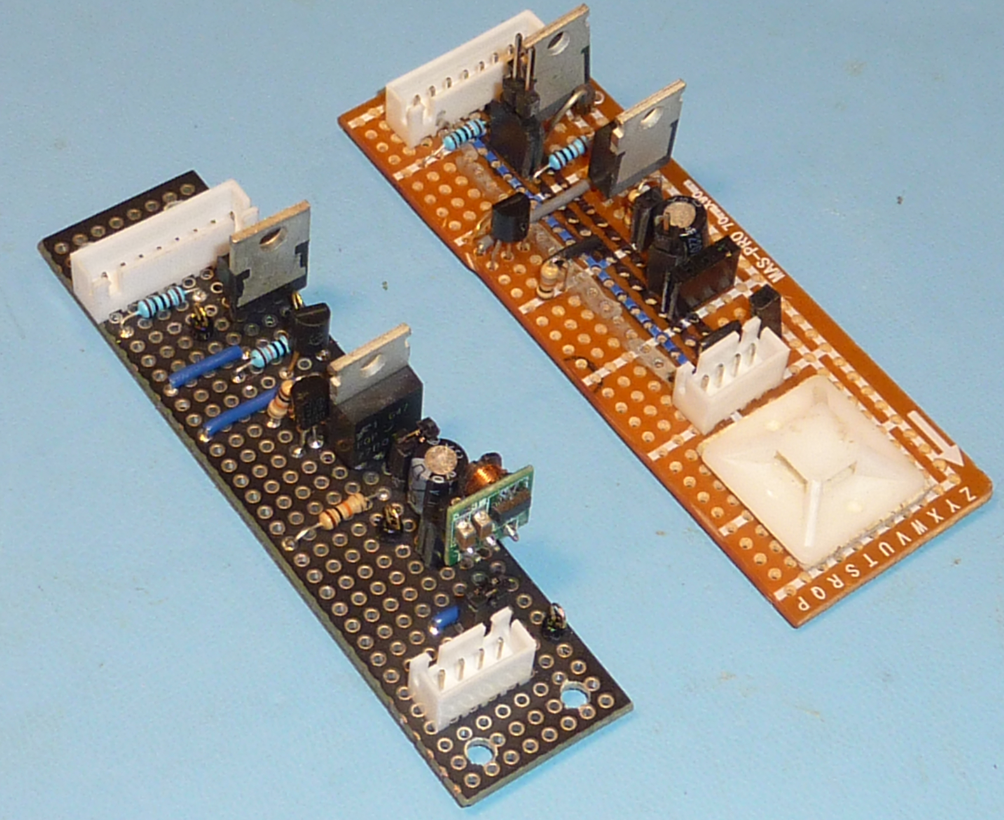
Here are photos of the new, slimmer power conditioning module
LiPo battery and module now fit side-by-side inside the vented enclosure
25% slimmer compared to the first version of the power conditioning module (on right)
Layout in KiCad
The schematic is here
As with all aspects of this project, it's 100% open software and hardware. The KiCad files can be found in the Street Sense GitHub repository
-
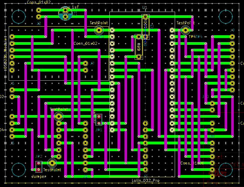
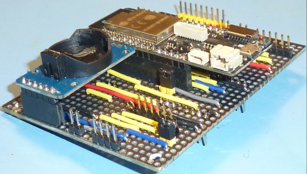
Designing a CPU Module
09/09/2019 at 18:42 • 0 commentsThe next transformation from breadboard to PCB is the CPU Module. If you look at the schematic it might be better called a "connector module" or a "glue module".
This hardware module serves to connect all the peripherals and other hardware modules to the ESP32 microcontroller. Some connectors terminate at switches and buttons which will be mounted on a user accessible panel. Other connectors terminate at the sensor units: I2S microphone and the PCBs holding the air quality sensor units.
The PCB construction uses stripboard techniques with KiCad as the layout tool.
Some notable PCB design considerations:
- jumpers for the battery and USB inputs - to allow measurement of current for various operating modes.
- test points on all power and ground signals
- three connectors are placed on the back side of the PCB. These connectors service hardware modules that are located inside the external enclosure. This construction choice exploits a key benefit of plated through-hole stripboard construction - the ability to place components on both sides of the PCB.
Layout
Populated board
-
Revisiting Stripboard Techniques
08/01/2019 at 14:34 • 0 commentsI ran across an interesting blog post on using KiCad to layout a stripboard design.
Designing professional looking stripboards using Kicad
So far I've been using manual layout methods for my stripboard prototypes. The layout approach using KiCad appears to offer a better way to make an efficient layout.
I decided to rework the sensor board layout using KiCad. As well, I'm splitting apart the schematic into 3 separate schematics, one for each physical module. The new schematic for the Spec Sensor module is here.
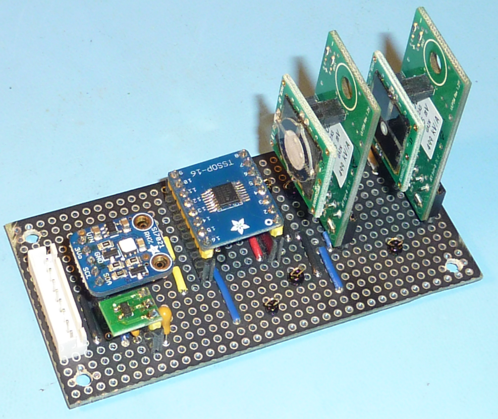
As part of this journey I had some stripboard manufactured by JLCPCB, with the stripboard layout done in KiCad. 5 quality stripboard PCBs (10cm x 10cm) can be manufactured for USD $2.00 plus USD $8.09 shipping to Canada.
The results were excellent. I decided that this work was worthy of a separate HD IO project called Stripboard Meets KiCad
Here is the completed sensor module using the JLCPCB stripboard
-
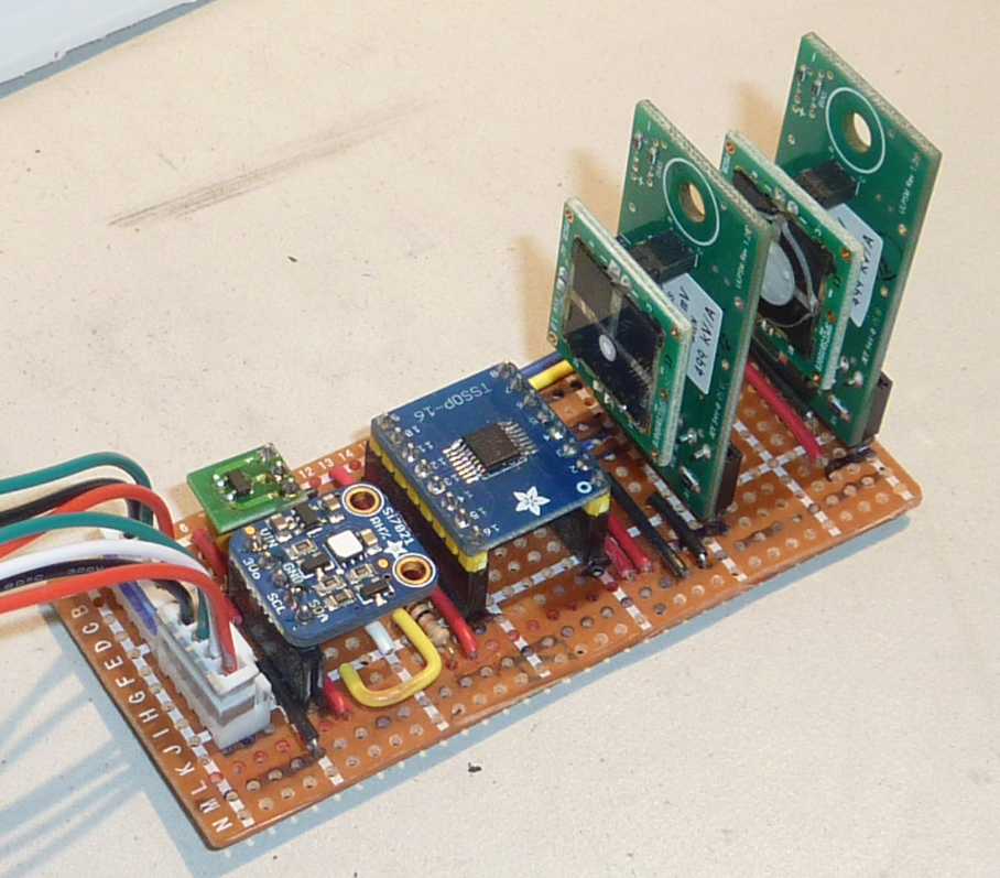
Designing an Ozone and NO2 Module
06/26/2019 at 19:07 • 0 commentsContinuing with stripboard construction methods, the ozone and NO2 sensor module was built. This module also contains a LDO voltage regulator, the 24-bit ADC, and a temperature sensor. The readings from the two sensors will need to be compensated wrt temperature - that is the reason to locate the temperature on this module. An overview of the modules is described in an earlier project log From Breadboard to Enclosure - Part 1.
This stripboard module can be considered a stepwise improvement. Compared to the boardboard prototype it should give improved performance for the Spec Sensor modules, but will still be lacking compared to a properly laid out PCB.
The module includes the major components U6, U8, U9, U10, U11 found in the schematic.
-
Designing a Power Conditioning Module
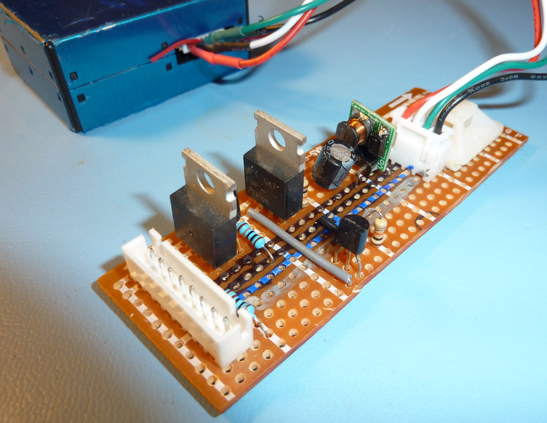
06/19/2019 at 14:13 • 0 commentsBuilding the power conditioning module for the particulate sensor is the subject of this log. The components in this module include all of the MOSFETS, transistors, diode, and the DC-DC boost converter. An overview of the modules was described in Modular Design Concept
The purpose of this module:
- Provide 5V power to the particulate sensor, for both USB and Battery power
- Provide a 3.3V compatible digital signal that will allow the MicroPython code running on the ESP32 the ability to turn off the DC-DC converter. Turning off the DC-DC converter eliminates the power consumption and noise of the particulate sensor
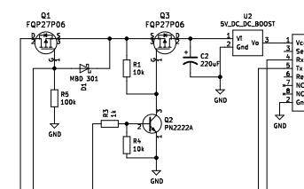
The components are shown below. The full schematic is here: schematic.
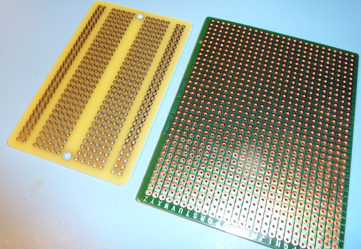
A soldered protoboard will be used for construction. For protoboard, I either use Adafruit Perma-Proto (left in photo below) or a generic stripboard (right in photo), cut to a custom size.
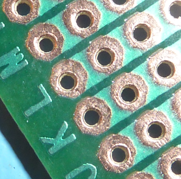
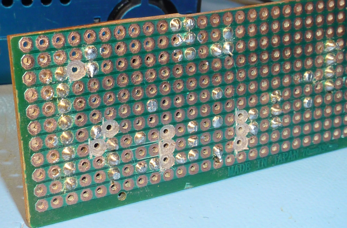
The Adafruit product is high quality - the through holes are accurately drilled and plated. The stripboad is somewhat lower quality - no though hole plating and inconsistent drilling which can lead to track lifting if there is any rework. The photo below shows some of the off-center drill holes on the stripboard.
However, compared to a Perma-Proto board a stripboard module can be designed with a denser component layout, leading to a smaller module. In the end, the need for a small module size led to the selection of stripboard.
Related stripboard idea: There is high quality stripboard that is available, but it comes a significant price premium. I think it might be possible to design a stripboard in KiCad and then have it built by a custom PCB manufacturer. I am seeing low-cost PCB manufacturers offering 3 PCBs (10cm x 10cm) for USD $10 + shipping. These PCBs would have plated through holes and solder resist between the holes, and hopefully accurate hole placement. I might explore this avenue and document the results in a Hackaday project.
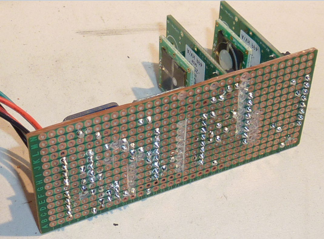
The completed power conditioning module is shown below. I am using polarized JST connectors for connection to the particulate sensor and cpu module.
 Mike Teachman