 Hexabitz
-
1Acquire a few standard power strips
I got few power strips from Home Depot. It's really difficult to tell if there's enough room inside before you open them up so you might need to experiment with few models (but at least make sure they're wider than a single module, i.e. 30mm, which almost all power strips are.) In some power strips, there's enough space to stuff in modules without any modifications. In other ones, you might need to remove the power switch or one or more outlets. In most cases, you will probably need to at least remove some internal ribs or drill some holes. Also, wiring gets tight with thick power cables so try to get the spaciest power strip you can find!
-
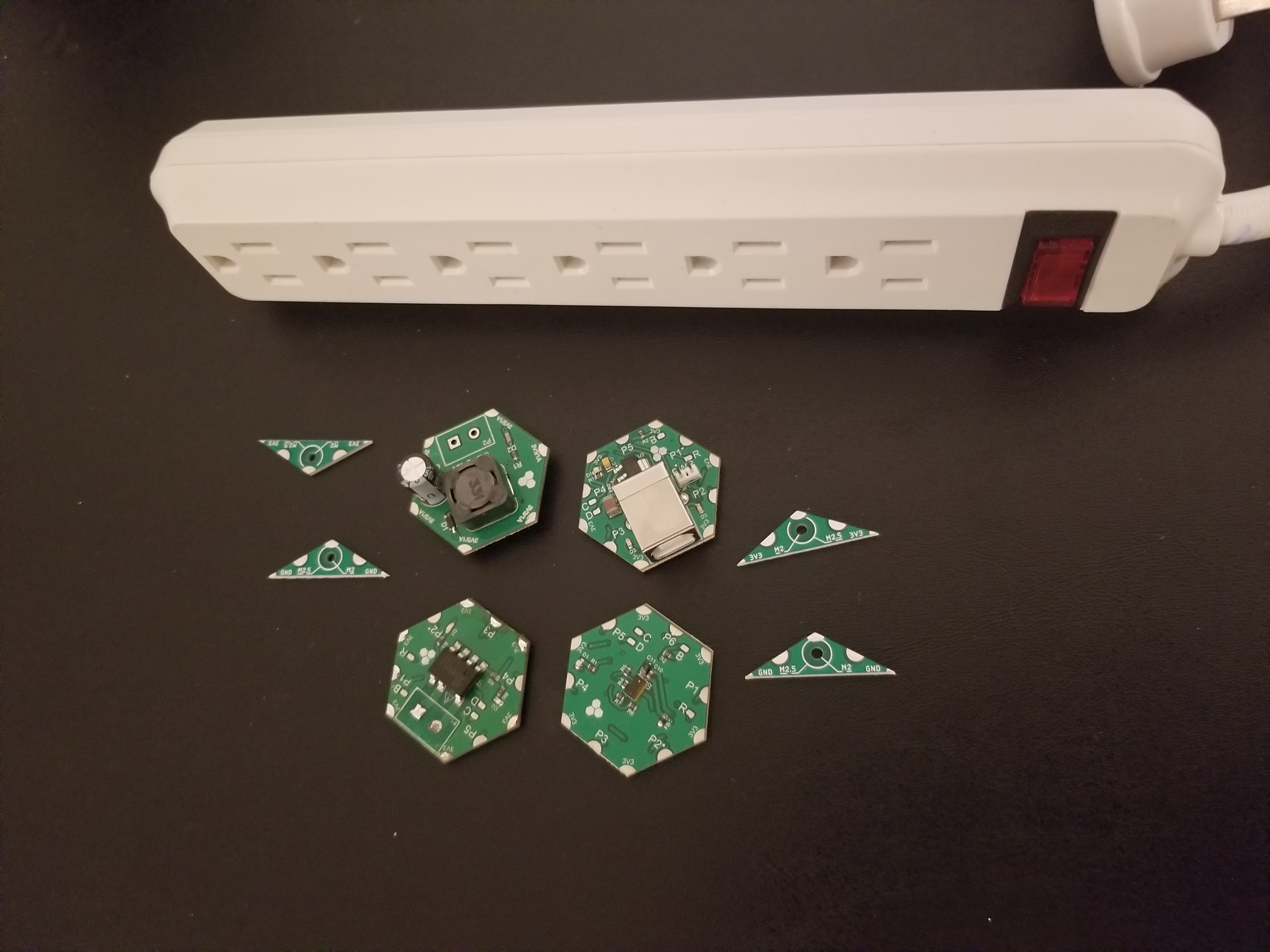
2Choose what modules you want in there
I modified two power strips. Once has the IR ToF sensor module (H08R60) to replace its power switch so that you can use hand gestures to turn on/off and the other one has a BLE and a USB modules so that you can control it via a smartphone or connect to your PC and use the CLI. Of course you need an AC relay and a 3.3V power supply as well as few mounting modules. Here's the complete list.
Setup 1
- 1 x 600 VAC / 1.2A Solid State Relay Module (H0FR60)
- 1 x 3.3V / 1A DC-DC Buck Power Supply Module (H03R00)
- 1 x Time-of-flight IR Sensor Module (H08R60)
- 4 x M2/M2.5 Triangle Mounting Hole Module (T00R10)
- 1 x power strip
- M2 nylon screws and spacers (height according to your design)
The USB module is optional.
![]()
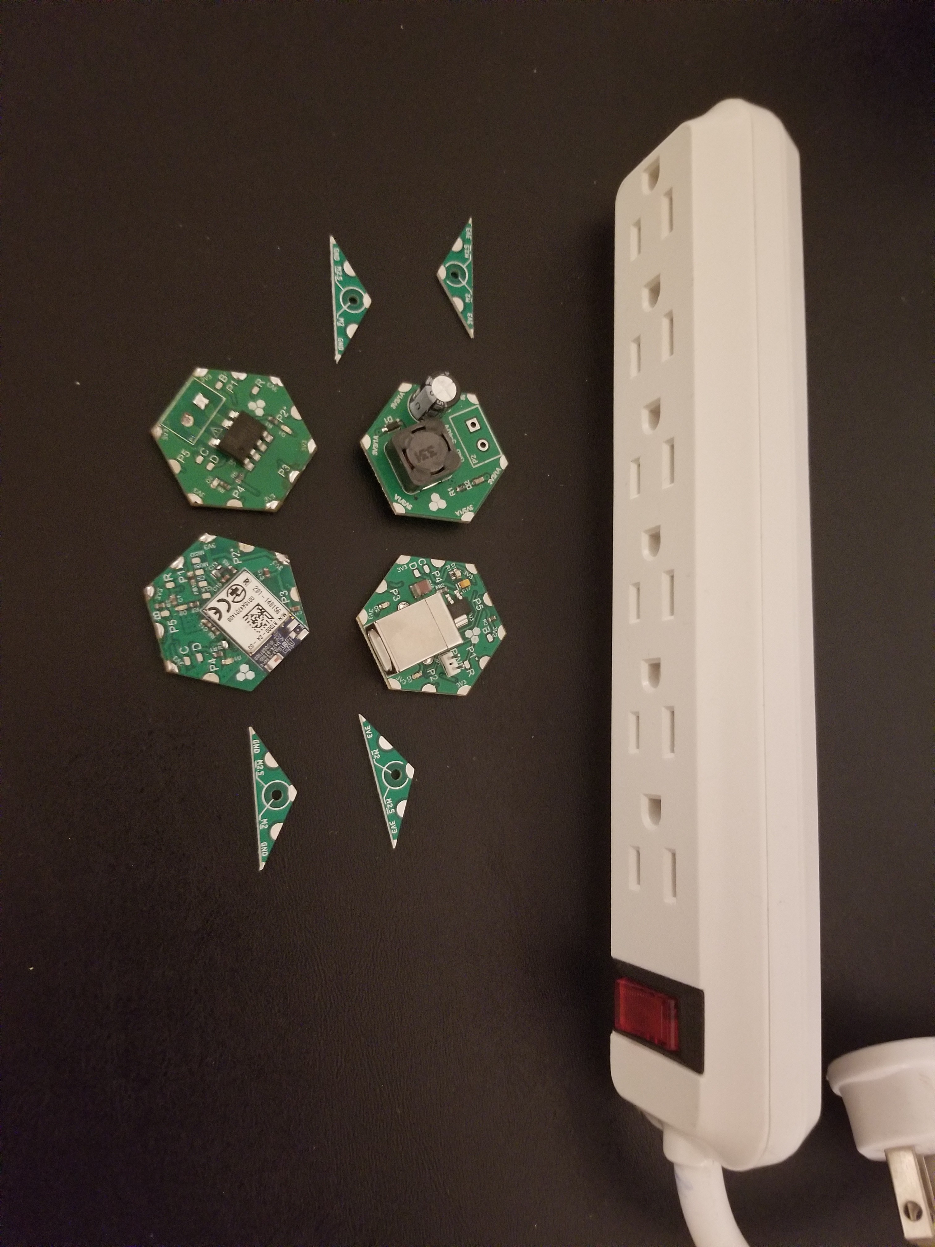
Setup 2
- 1 x 600 VAC / 1.2A Solid State Relay Module (H0FR60)
- 1 x 3.3V / 1A DC-DC Buck Power Supply Module (H03R00)
- 1 x Bluetooth V4.0 Dual Mode Module (H23R10)
- 1 x Mini USB-B-to-UART Converter (H1AR20)
- 4 x M2/M2.5 Triangle Mounting Hole Module (T00R10)
- 1 x power strip
- M2 nylon screws and spacers (height according to your design)
Ended up using Mini USB-B module instead of the USB-B in the picture to reduce size.
![]()
-
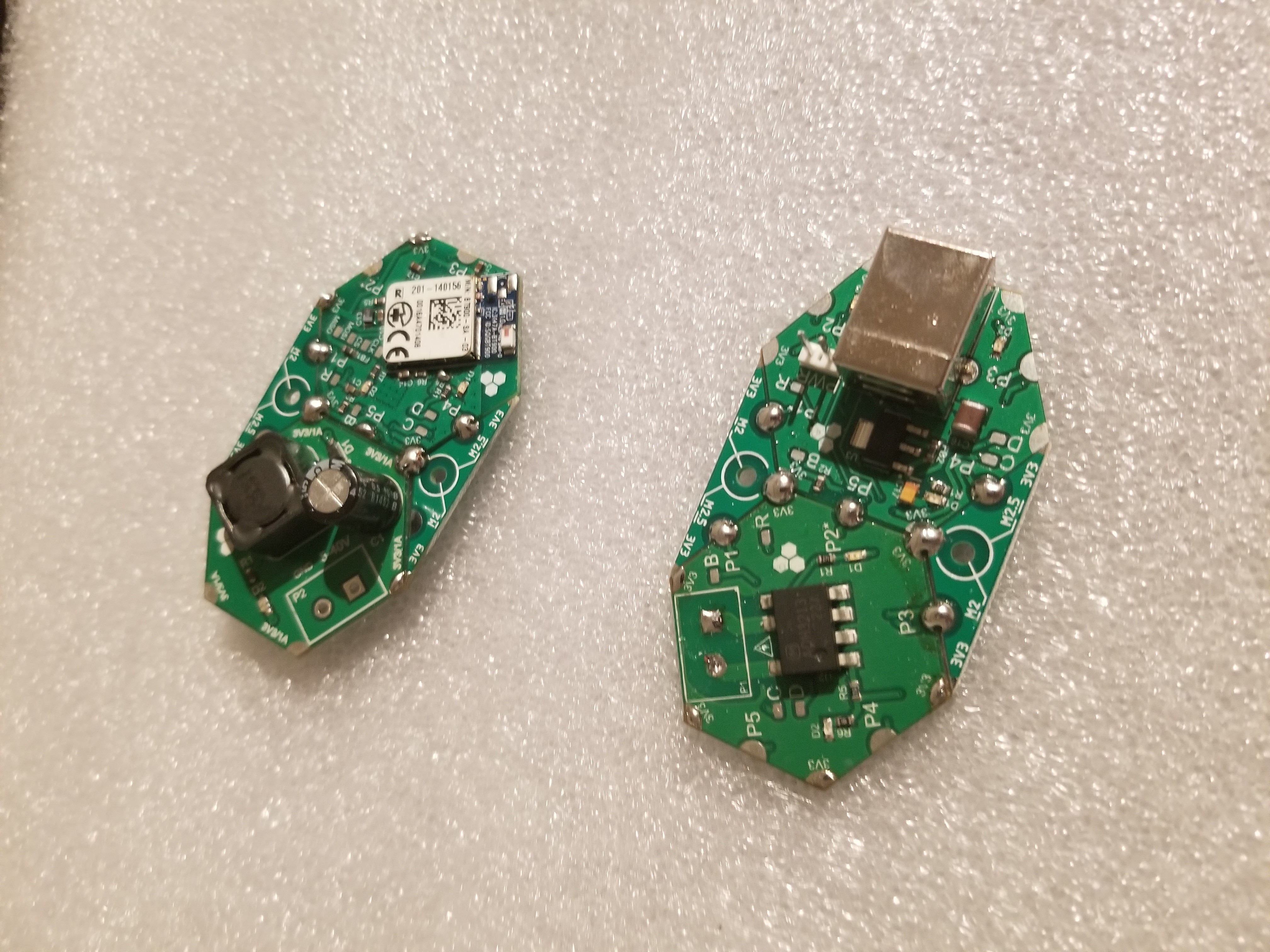
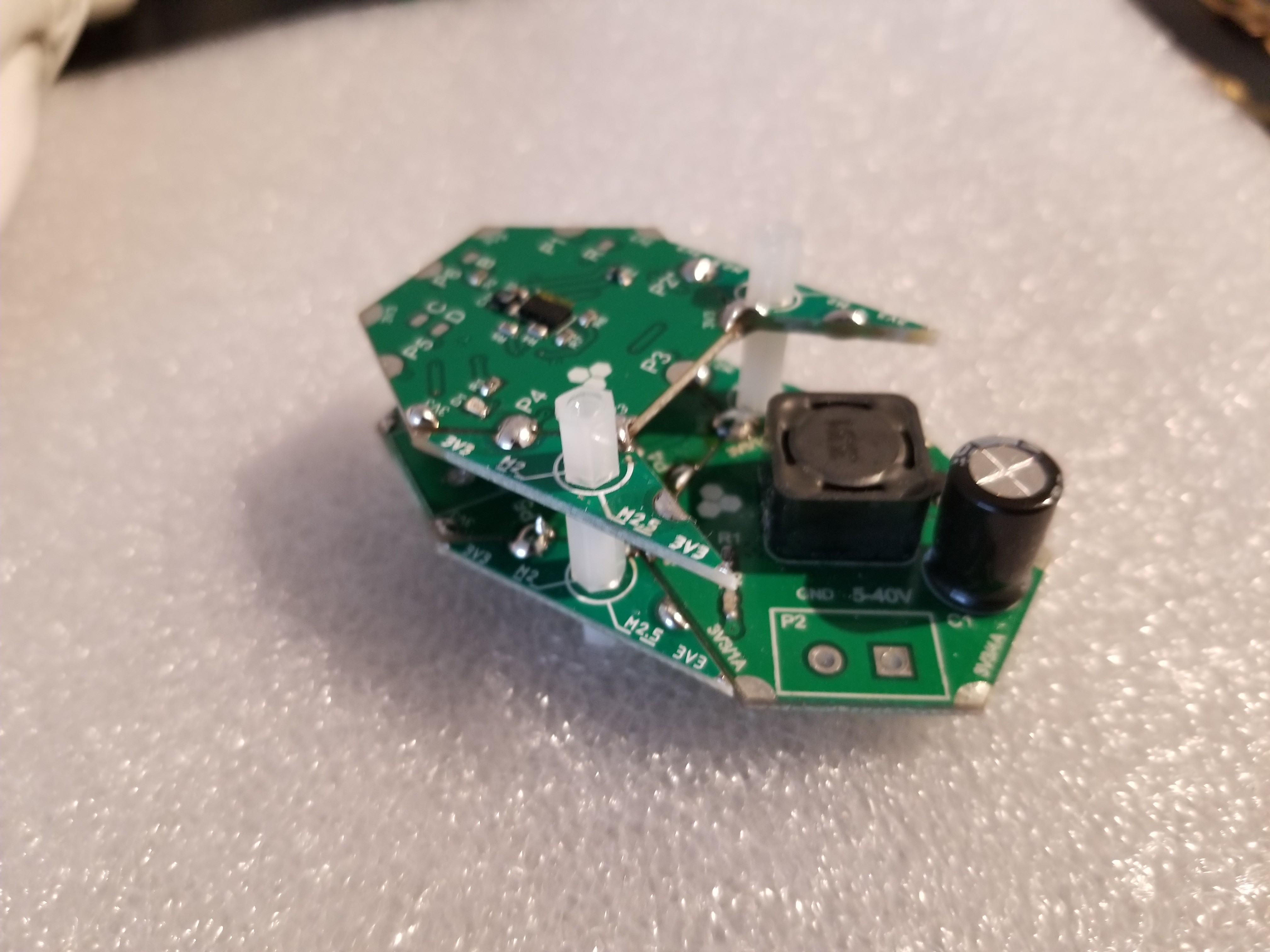
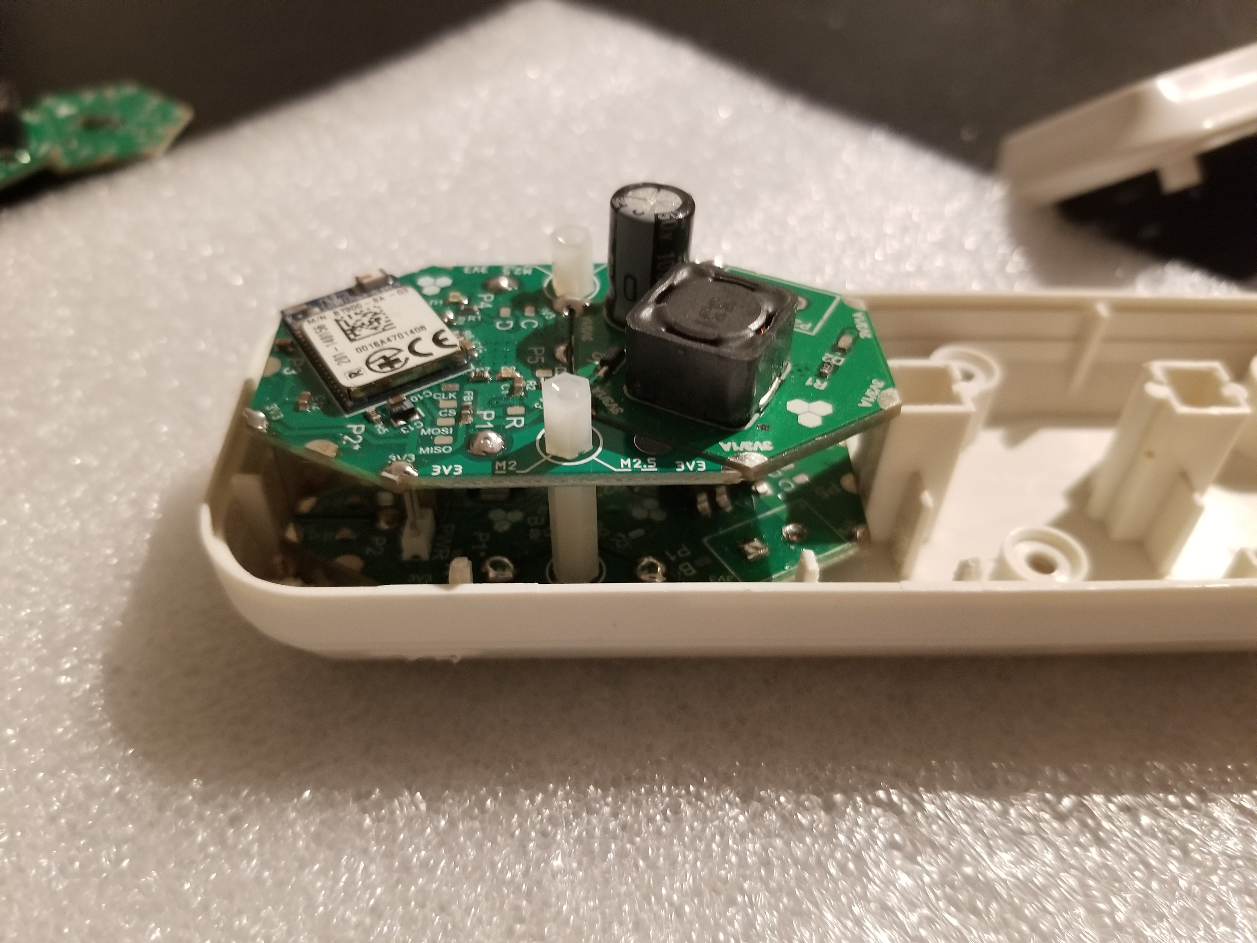
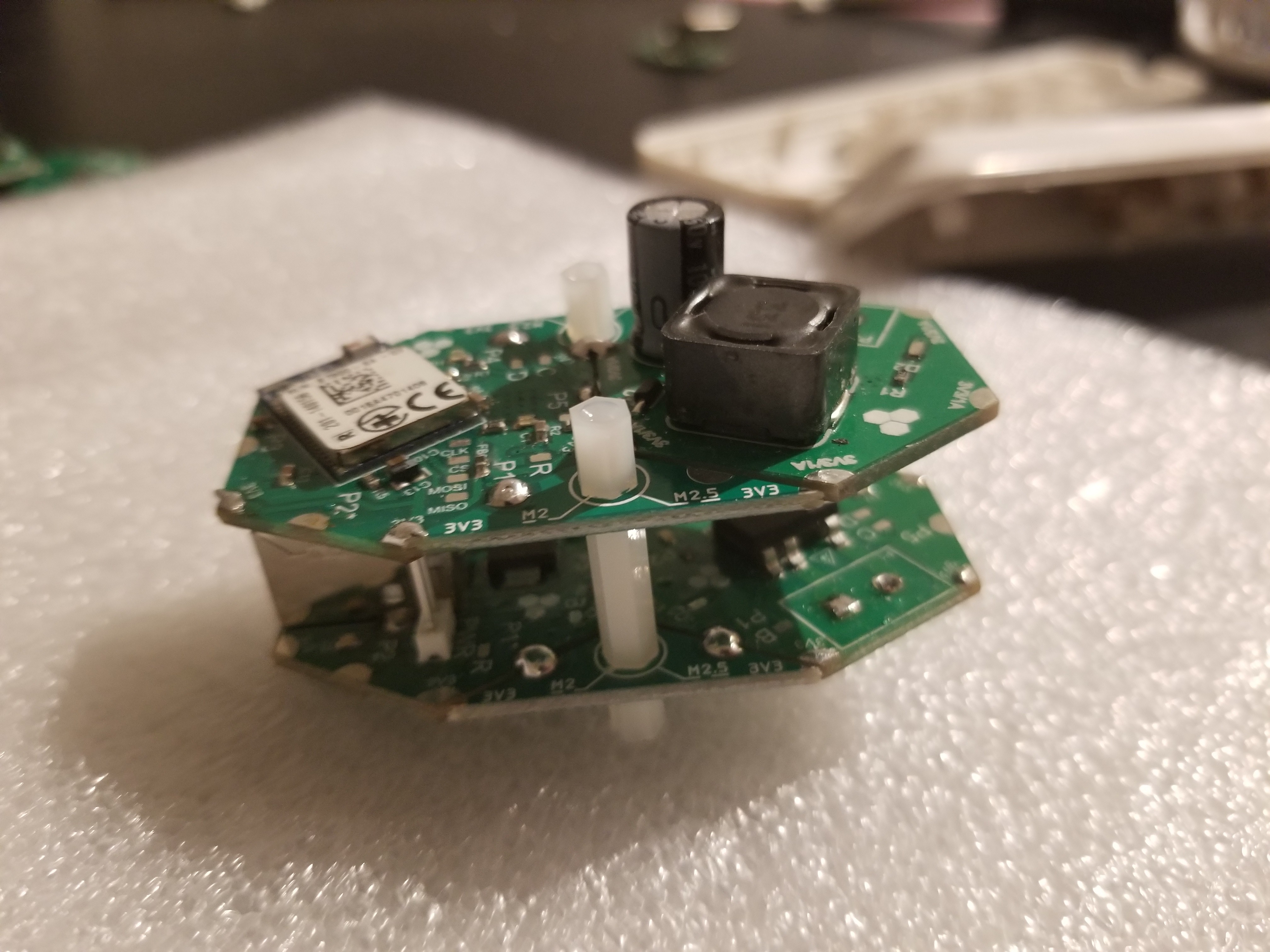
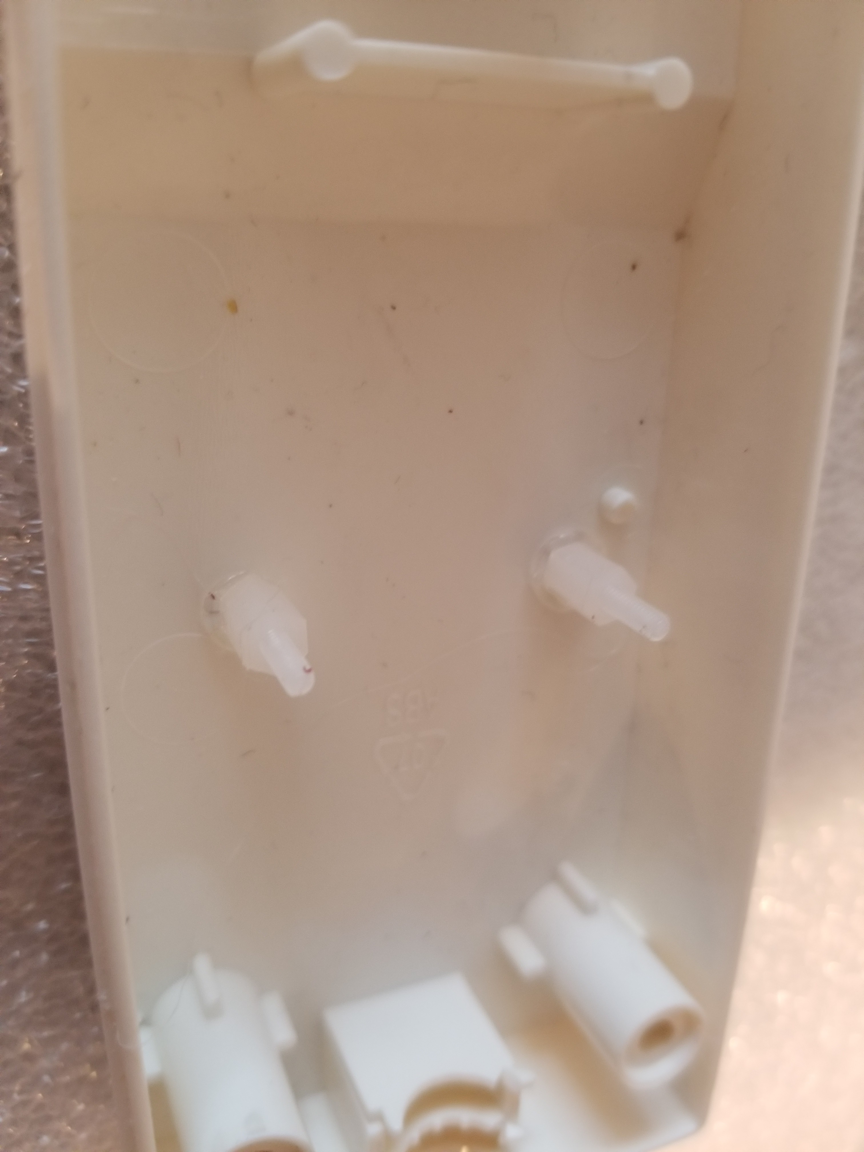
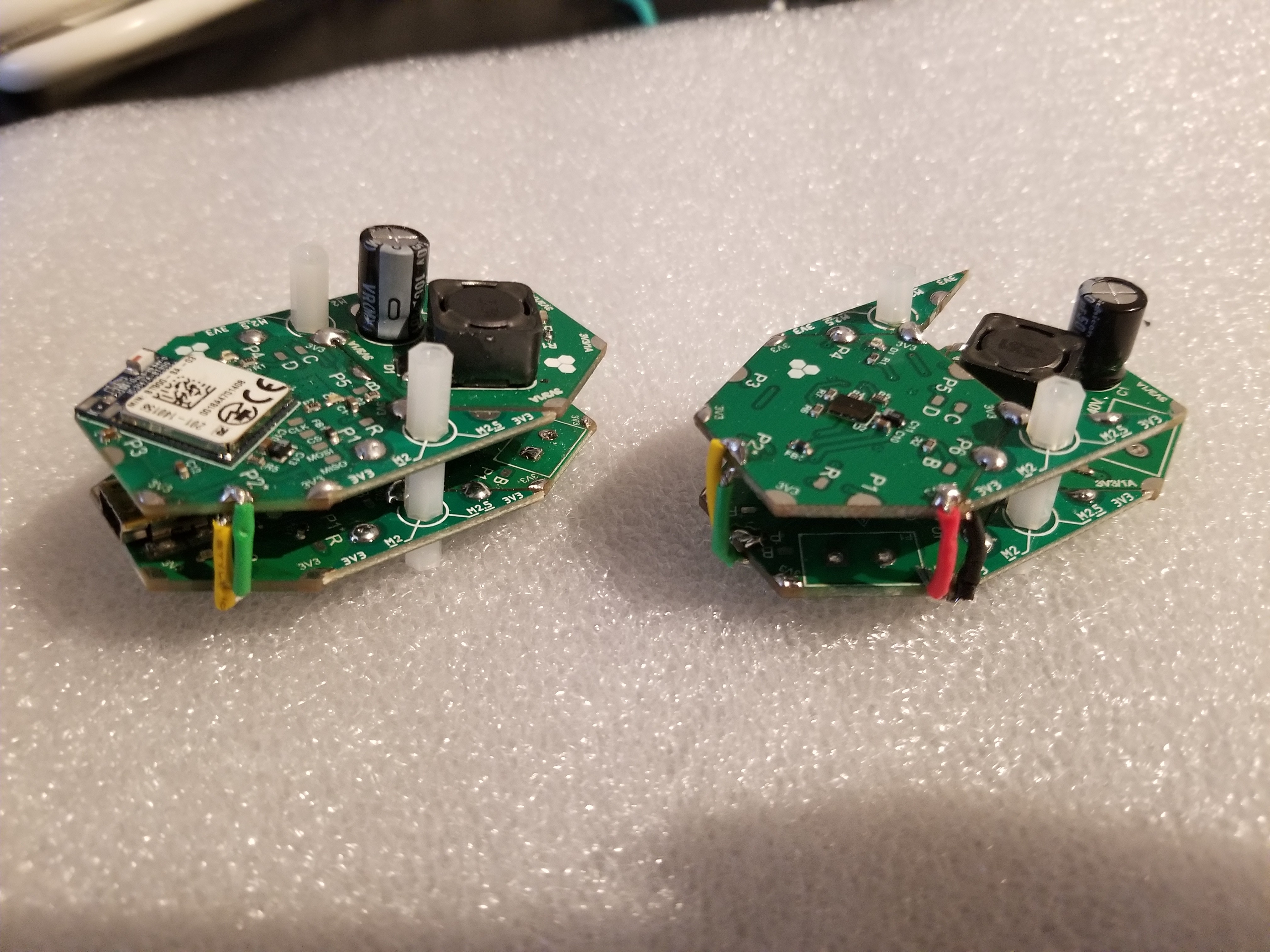
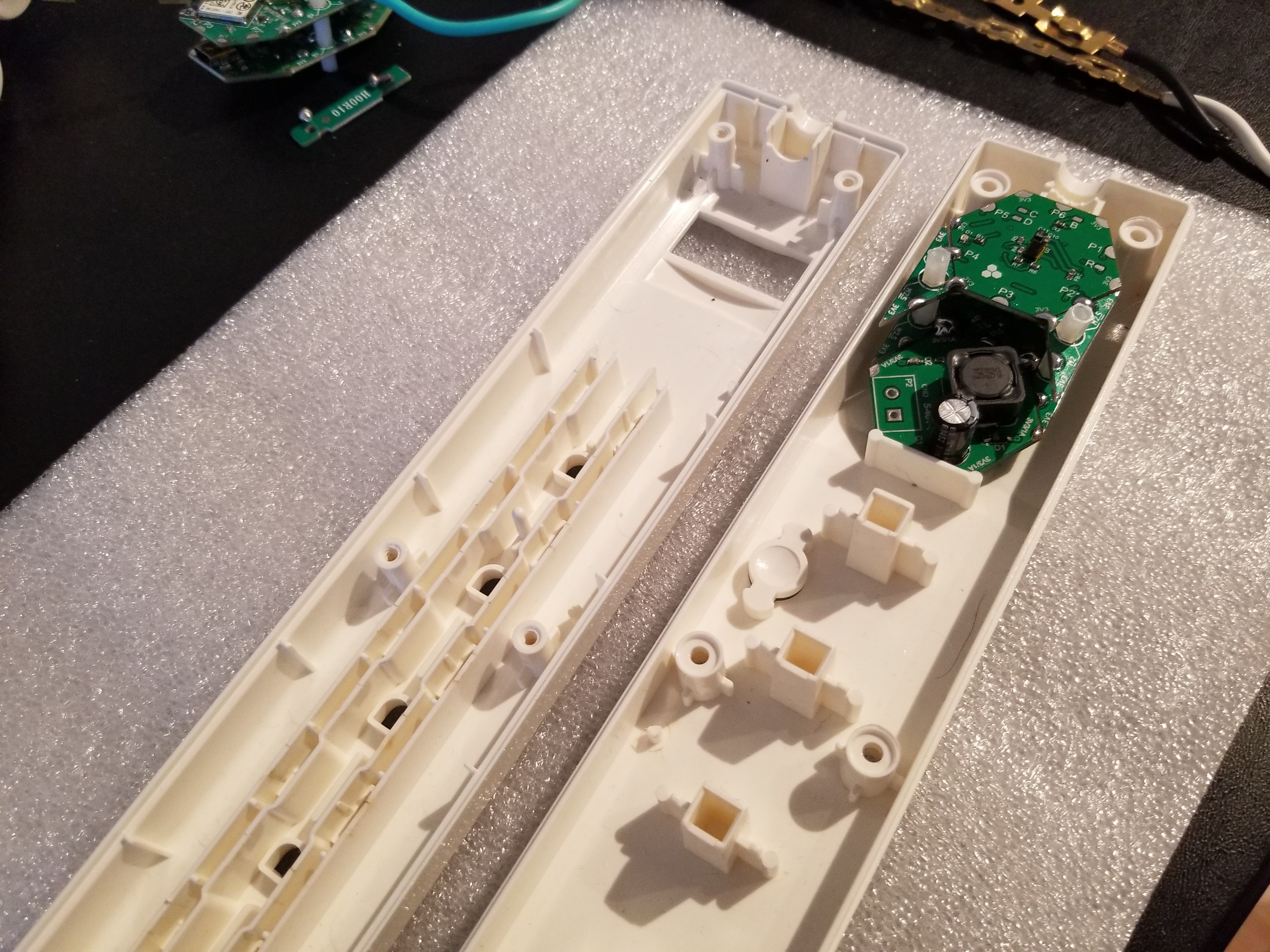
3Start assembling the modules together and find out best fit
This step will require some iterations. You will need to find the best place inside the power strip and maybe remove some internal features that are blocking the modules. Remember that you can also go vertical and tune the vertical spacing based on module height, available space the way you want to access your modules, etc.
![]()
![]()
![]()
![]()
![]()
![]()
-
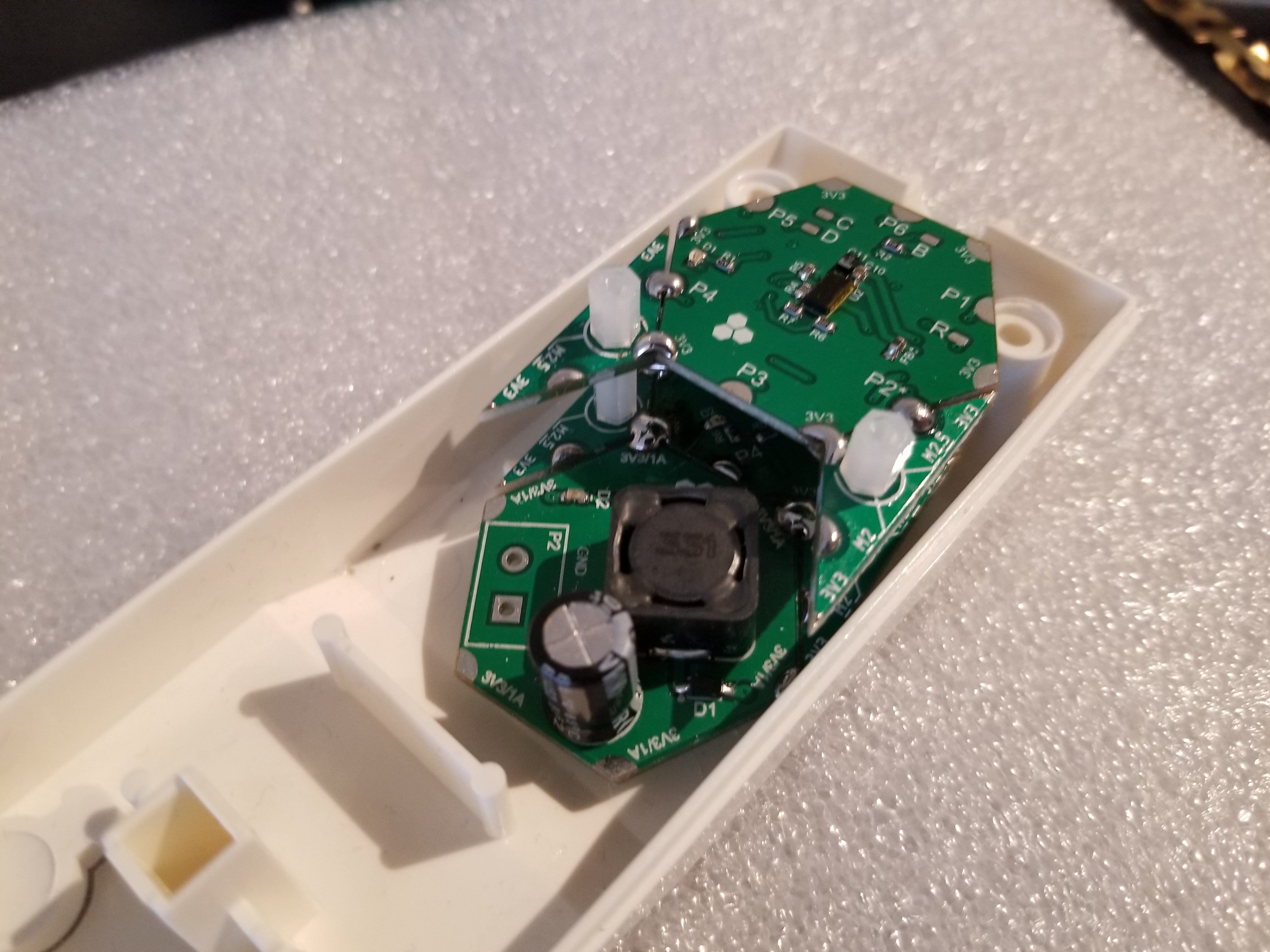
4Find a way to constrain your modules inside
You might end up drilling holes and using metal screws or gluing nylon spacers from the inside. Sometimes when the space is really tight, the modules will be constrained just by their cables.
![]()
-
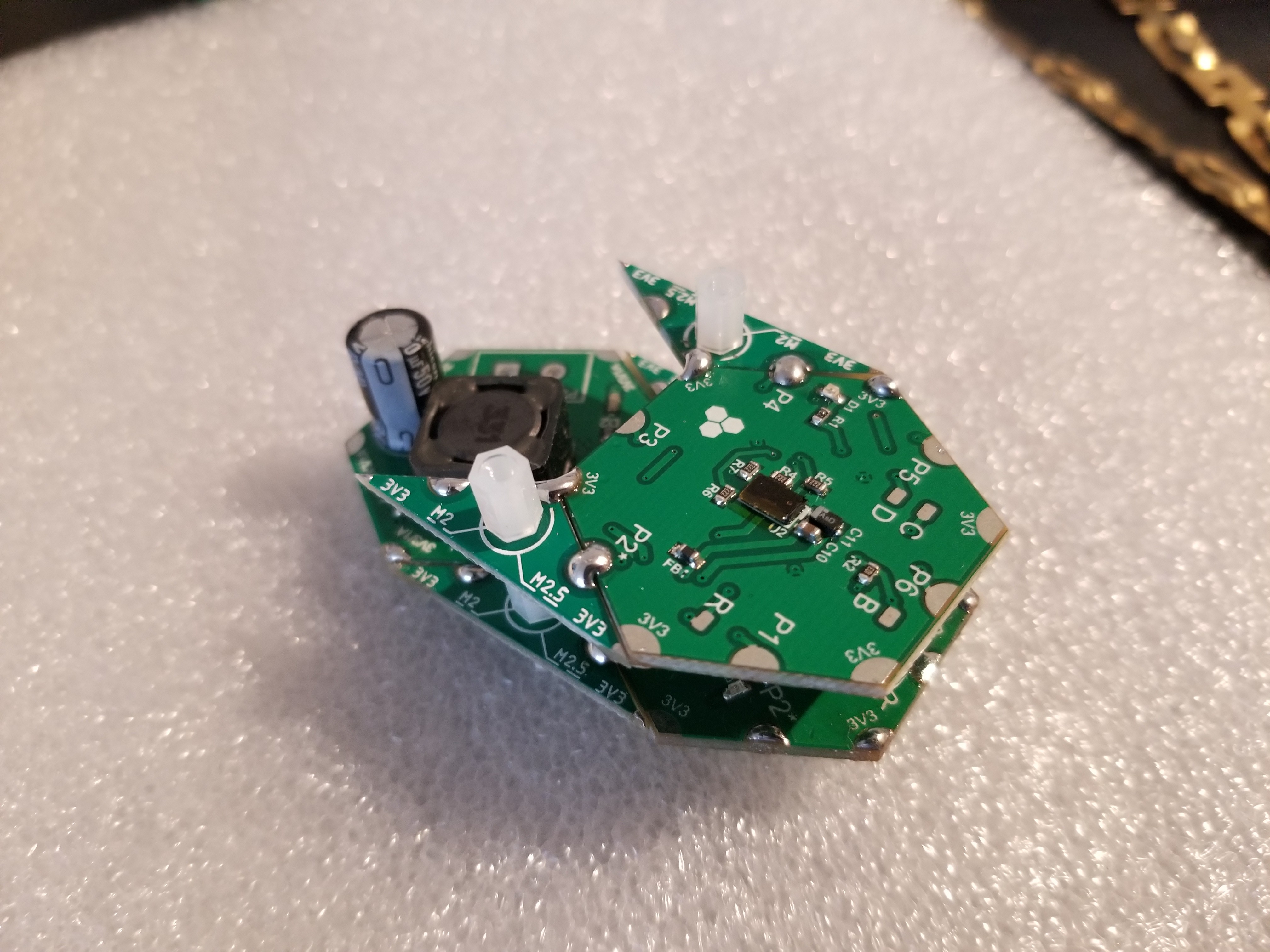
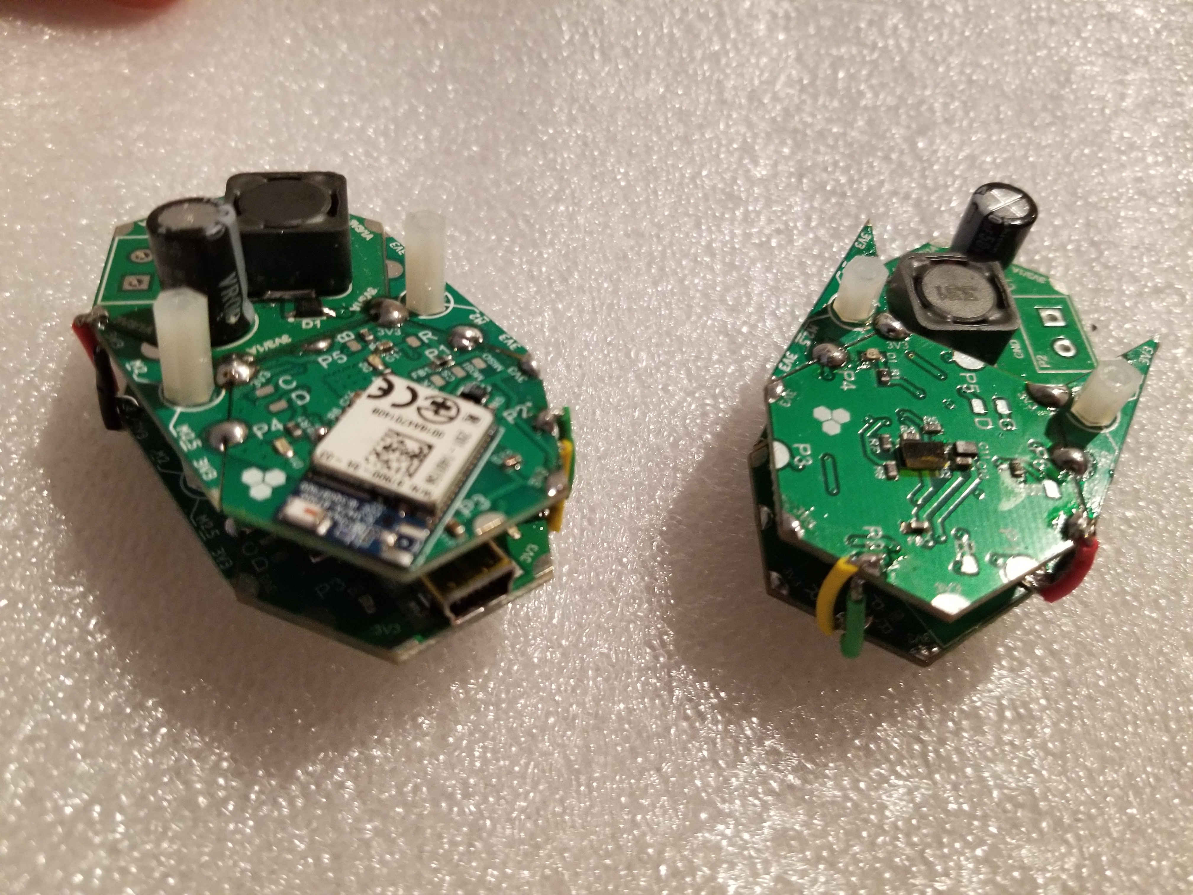
5Remember to connect the modules vertically!
You need to bridge power vertically and at least one array port if you vertical modules that should communicate with each other. I designed my array so that I can remotely program all modules when I'm connected to one of them. This way I can update firmware on any module I want. We will have soon triangular vertical extension modules so that you don't have to make these messy jumpers!
![]()
![]()
-
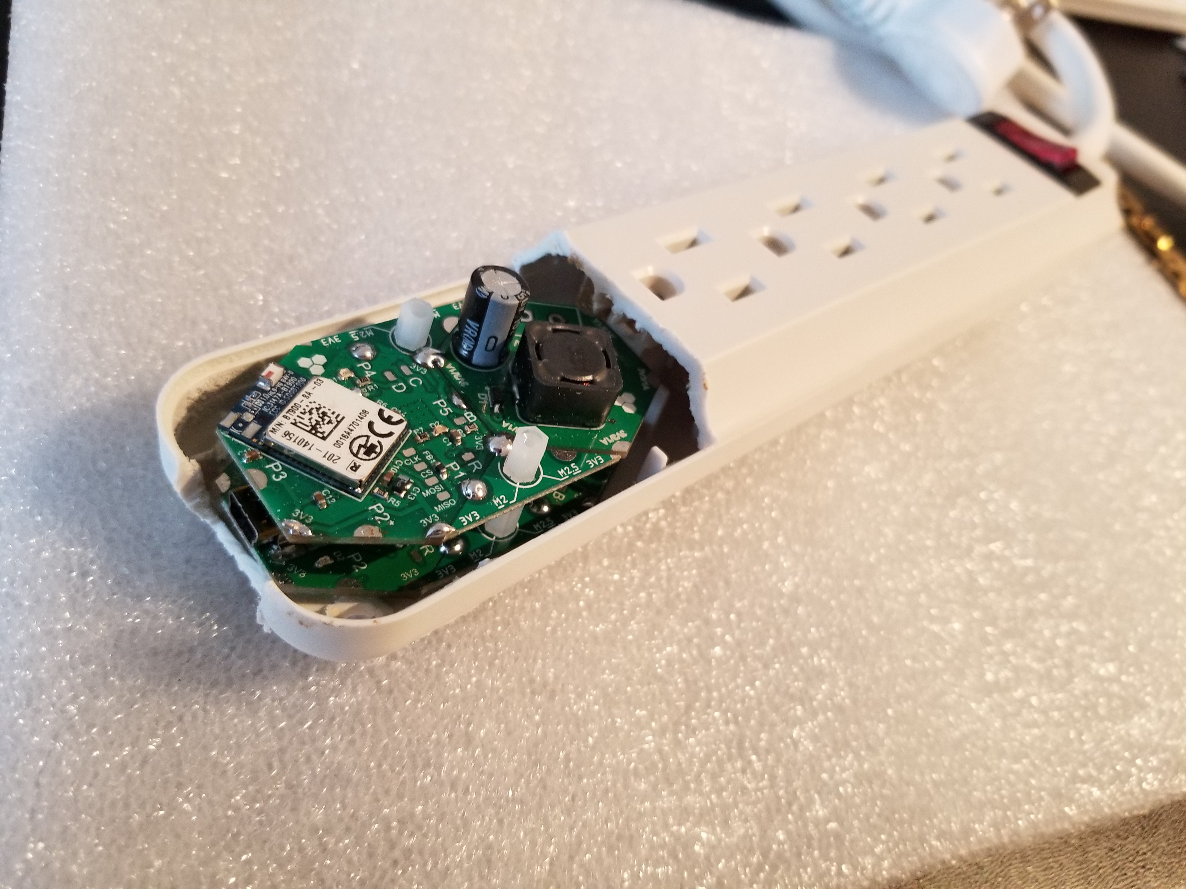
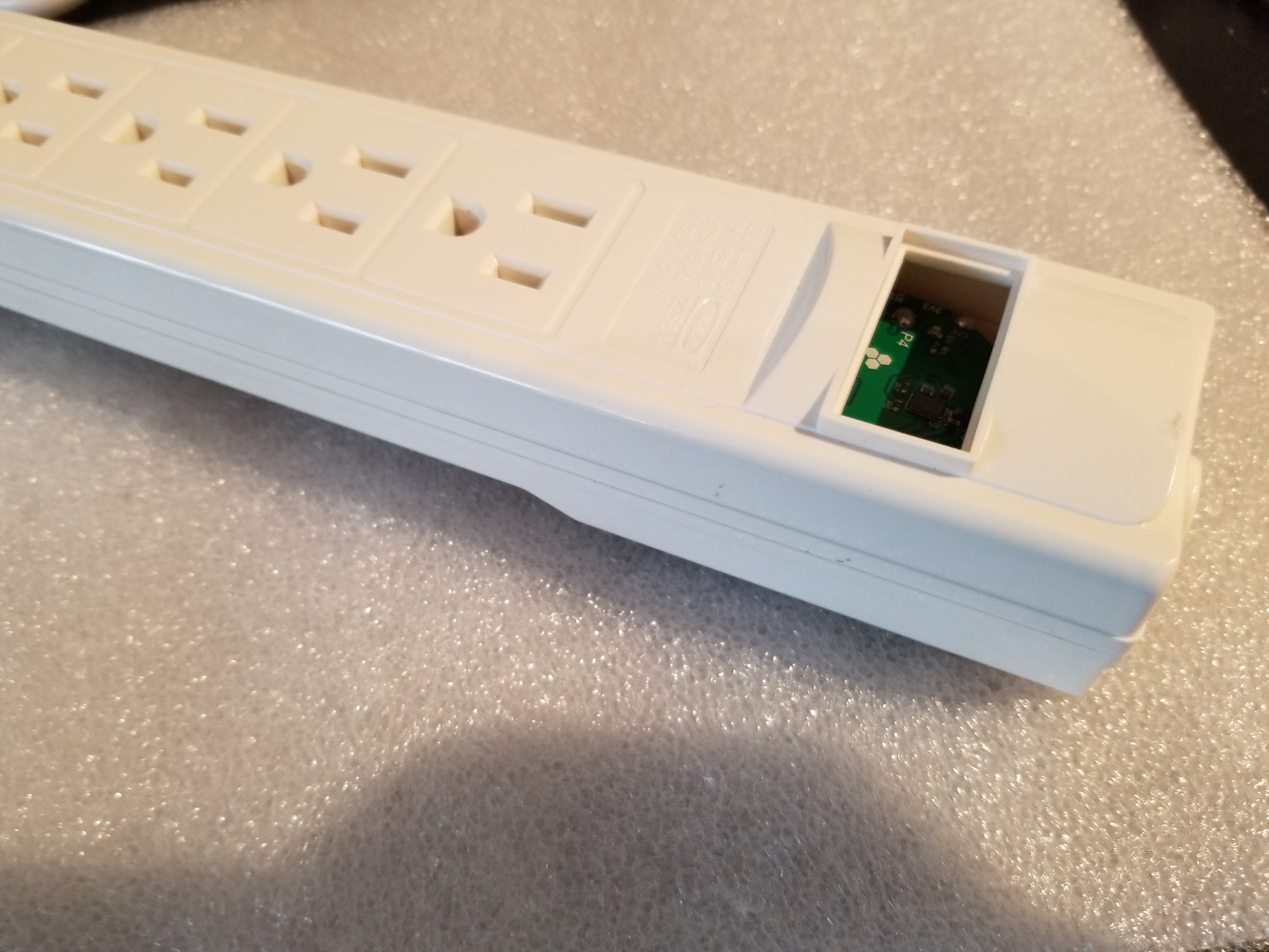
6Route your cables and assemble back the power strip
One of the power lines needs to be cut, routed to relay module and then back to power sockets. I used an extern AC-DC wall adapter to power the 3.3V DC-DC module since it's really difficult to fit it inside. One of the module designs didn't actually fit inside so I had to remove part of the cover. One can 3D-print a transparent cover to give an awesome look! Also don't forget to make an opening for USB port.
![]()
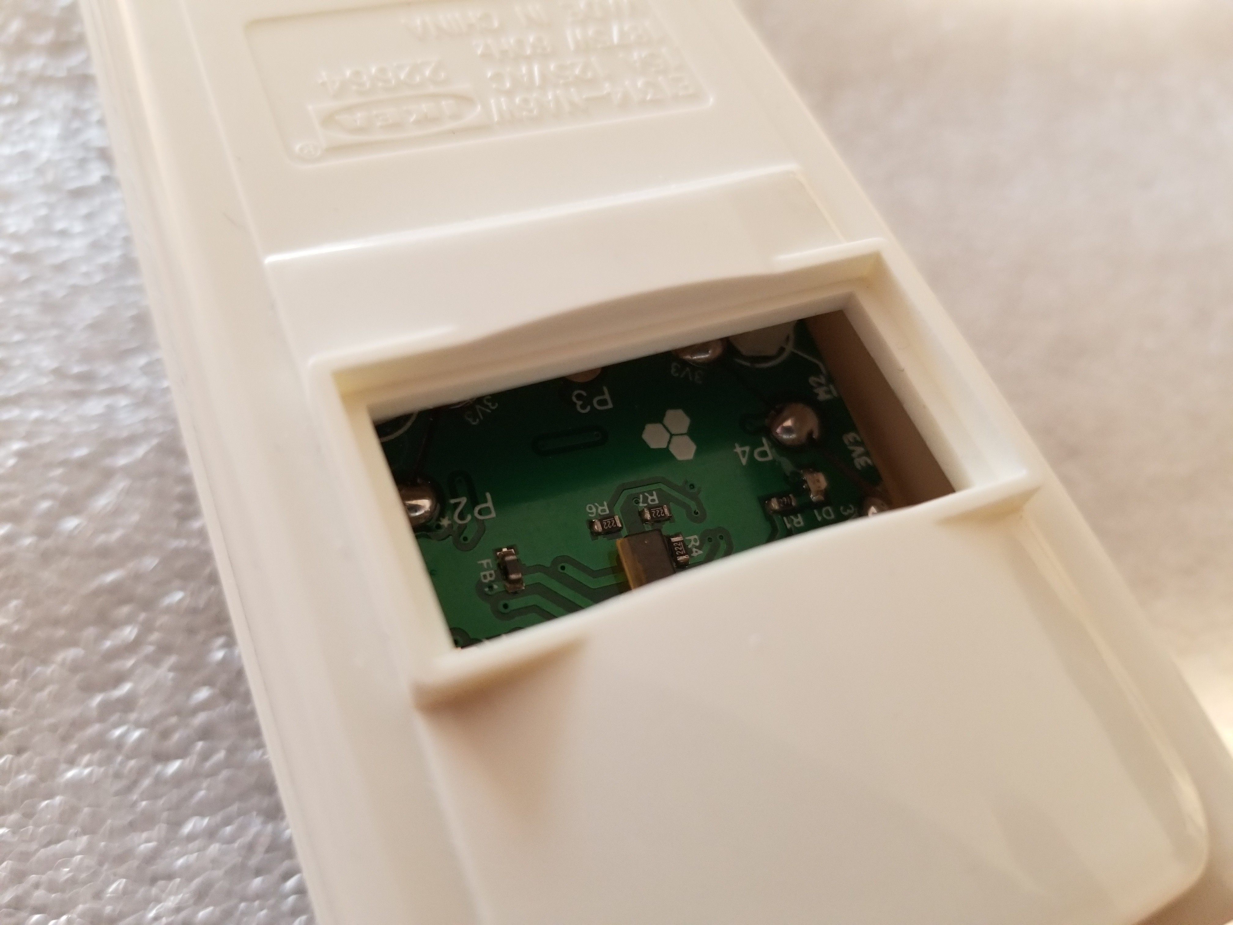
The seconds design fit perfectly and the IR sensor aligned with the power switch opening making it a great success!
![]()
![]()
![]()
-
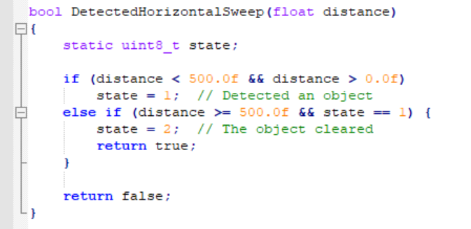
7Testing the gesture-controlled power strip!
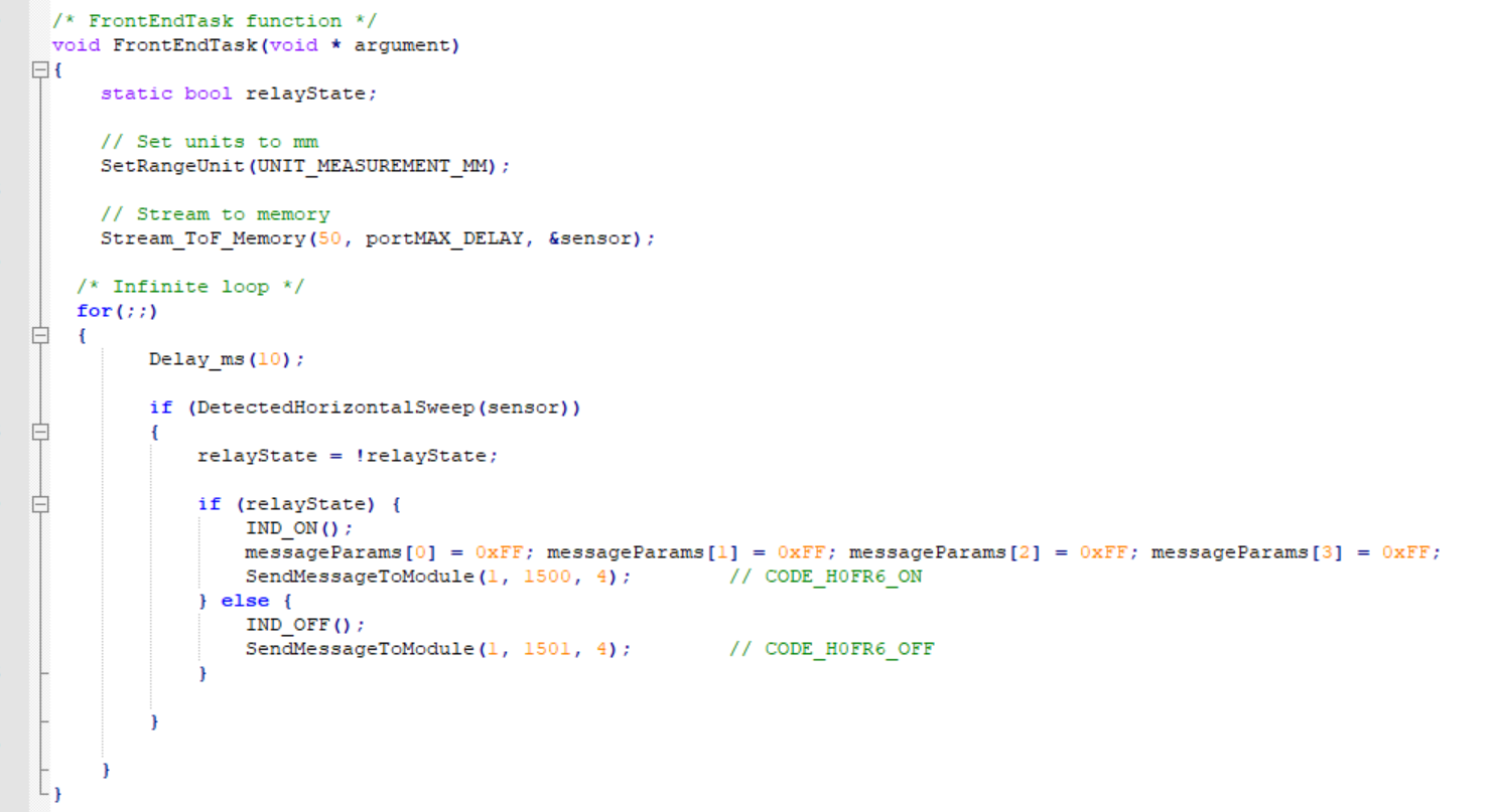
I loaded standard H0FR60 firmware on the relay module. Check latest release here in the Compiled folder. For the IR module (H08R60), I made this simple code (attached project) that detects a hand sweep within 500mm range.
The FrontEndTask simple configures the IR sensor to stream values to a memory location (the sensor variable) and then checks for hand sweeps. If a hand gesture is detected, the indicator LED is toggled and the relay module is ordered to turn on or off via the appropriate. This can be simplified a little bit by directly sending a toggle message to the relay module but I wanted to keep the internal toggle state in the IR module in sync with the relay so that the indicator LEDs on both modules can be used to signal power ON state (the relay module has an orange indicator LED hard-wired to relay output).
And here's some testing with an AC lamp. So fun! If you move your hands quickly they might not get detected but the code can be sped up if needed to detect faster gestures.
-
8Testing USB control and setting up timers
Coming soon!
-
9Testing BLE control from a smartphone app
Coming soon!
Fancy Power Strip
Hack a power strip with some Hexabitz modules and remote-control your AC gadgets with BLE, USB, hand gestures or whatever you can think of!
Discussions
Become a Hackaday.io Member
Create an account to leave a comment. Already have an account? Log In.