 Alexander
-
1Why MQTT?
For the next phase of our tutorial series, I knew that we would be communicating with a cloud server. There are many different protocols for IoT communication, but MQTT has the advantage of being simple, lightweight, and fast. It can also be served using TLS encryption, making it secure as well. I wanted to dive a bit more in depth with the esp-open-sdk, and the best way to do so would be to write a library from scratch! So that's what I did. In this project, we will be looking at the library, as well as an example using it to communicate with Adafruit I/O, though any compatible MQTT server will work just as well.
The complete library is hosted on GitLab. There is a link in the sidebar, or you can just click here. I based the library directly off of the MQTT standard, which is open and available for anyone to read. I strongly recommend you take at least a cursory glance through it, or read a summary of how MQTT works. There is a brief description in the details section of this project, but a more thorough understanding will make using the library much easier.
We will be going through the library, but because it is quite long, I won't be able to go line-by-line as I usually do. Instead, I will focus on important sections, and also spend time explaining how the example code works, and how to integrate this library into a separate project. We will be doing just that in the next tutorial in this series, so stay tuned!
-
2What does the library do?
I admit, I'm not the greatest coder around; not by a long shot. I go for functionality over form a lot of the time. In this case, the library will take care of most of the work for you -- you just need to provide info about the Wi-Fi connection, the MQTT feed you want to publish/subscribe to, and functions to handle the various tasks that your project needs to do.
Specifically:
- It creates a TCP connection to the server
- It crafts and sends the MQTT portion of the TCP packets, leaving the rest of the TCP packet creation to the espconn library
- It interprets the responses from the server, potentially calling user callback function
The git repository includes an example file, to show how a user would use the library in practice. We'll take a look at both halves of the project, but I urge you to go read the code yourself, and comment if you have any questions! Unlike the previous parts, going line-by-line through the library isn't feasible or warranted -- it's simply an implementation of the MQTT standard. If you are interested in writing an MQTT library yourself, say for a different device or language, you can pick through the code while reading the standard to see how and why it's designed the way it is. I would be more than happy to help if you have questions -- check the Getting Help section in the project details.
The library is mostly based on two functions: tcpConnect() and mqttSend(). tcpConnect() establishes the TCP connection to the MQTT broker, by calling the espconn library functions provided as part of the SDK. mqttSend() handles all MQTT transactions. When called, it is passed an mqtt_session_t object which contains a pointer to the active TCP session. It constructs a packet based on the MQTT standard, and then uses this open TCP connection to send the crafted packet. Much of this function is dedicated to keeping track of the number of bytes generated and dynamically allocating memory, as MQTT depends on a precise count of the bytes in the packet (as most TCP-based protocols do).
Once the packet has been constructed and sent, it activates a keep alive timer which will automatically send MQTT PINGREQ packets to the server to keep the MQTT session open.
The code is fairly well-commented, and the header file mqtt.h has good descriptions of each piece of the related structures. Also, if you generate the Doxygen documentation, it compiles all that info into an easy-to-browse HTML site. The latest version of the Doxygen docs are automatically compiled by GitLab and are viewable here.
-
3One-Wire Communication
Besides communicating with Adafruit IO over MQTT, we also need to grab temperature samples from the DS18B20. This is mostly for testing, as full integration into a project will be in the next part of this series. The DS18B20 uses the 1-Wire protocol, originally created by Dallas (as was the DS18B20 itself -- the DS stands for Dallas Semiconductor) but now owned by Maxim. The protocol runs on one wire (of course) and most 1-Wire devices only need three connections - power, OWB (1-Wire Bus) and ground. Many devices support a special mode called parasitic power where the device can be powered by the OWB pin, needing only two wires to function.
In this example, we will be implementing only the most basic functions needed to get temperature data from the device. The 1-Wire standard is much more complex than what is presented here, including CRC checks for data consistency, 64-bit device addresses and more. However, because we only have one device on the bus, and we only want it to do one thing, we can ignore the vast majority of the standard and just focus on three things:
- The reset sequence
- Sending a command
- Reading data back
In our case, we will be sending the command to start a temperature conversion, followed by the command to read the scratchpad (registers) containing the temperature data. The full device datasheet is here. I'm not going to go too deep into how it works, because that's not the focus of this project. However, I will go over the code briefly so you can see what is going on.
![]()
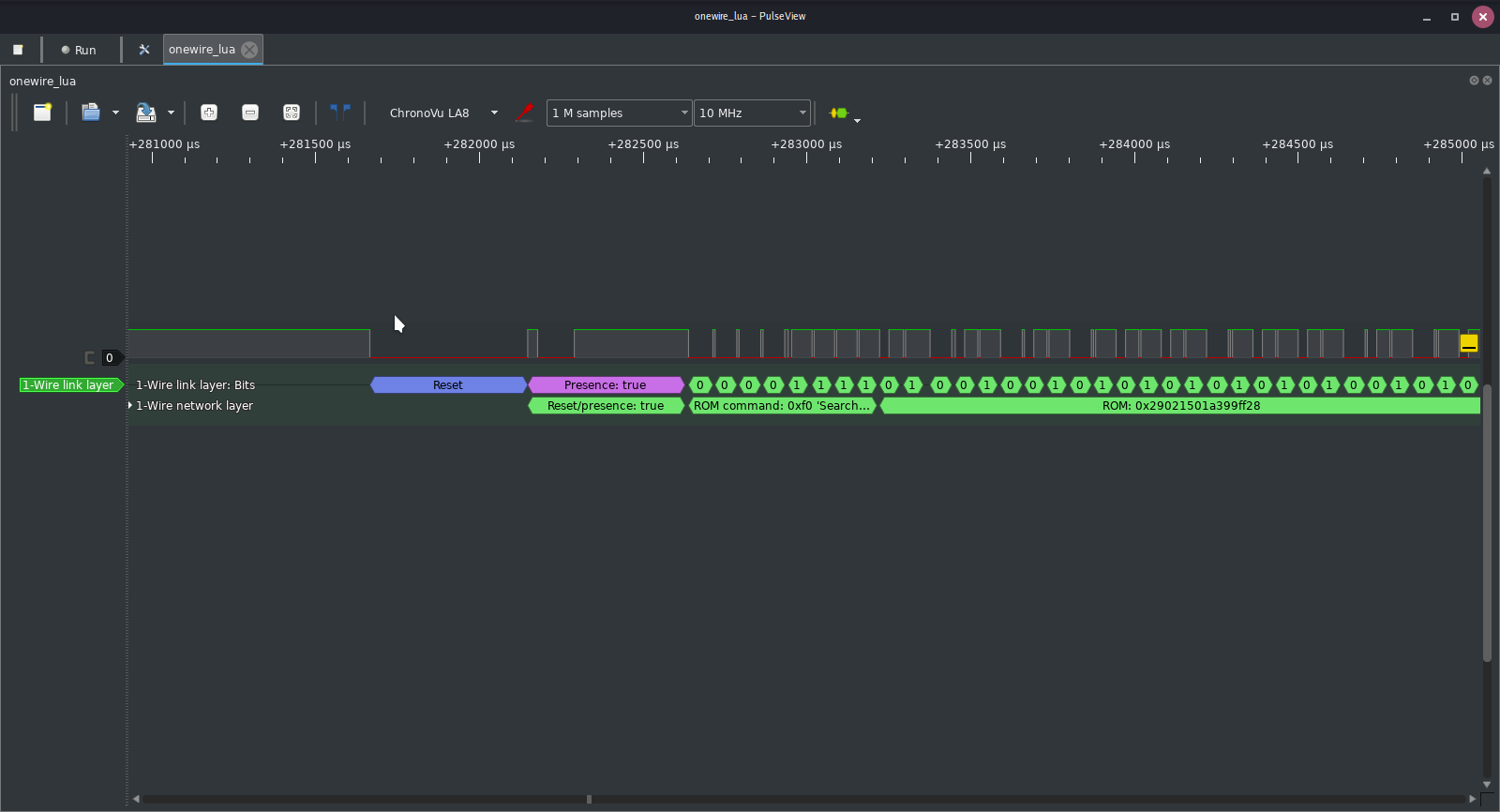
The NodeMCU Lua library for 1Wire implements the full protocol ![]()
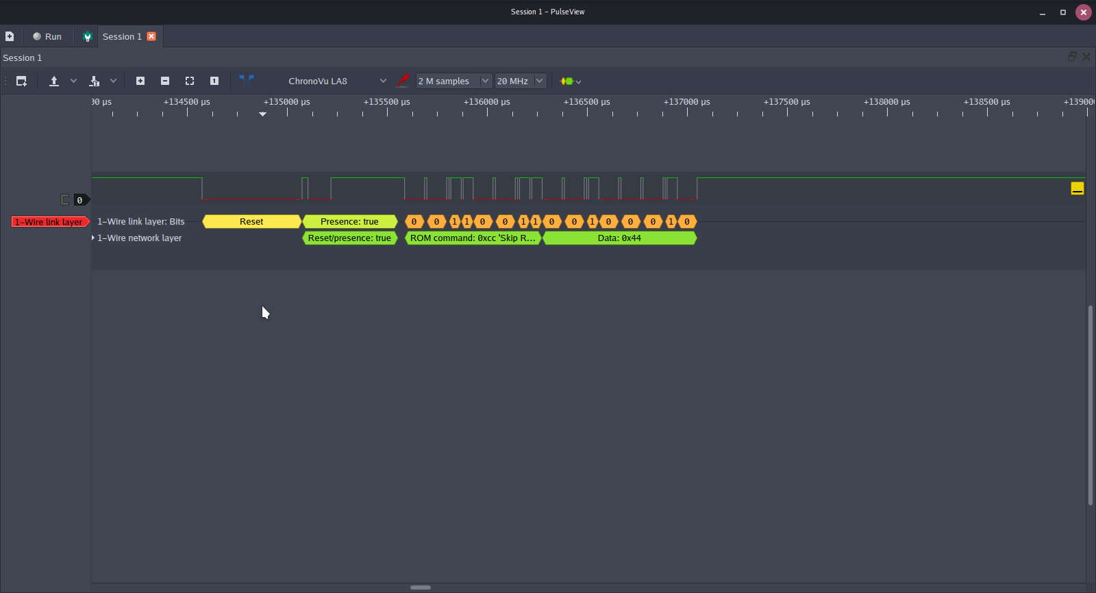
However, we will be using as few commands as possible Here is the code for the 1-Wire functionality. There are only two functions, reset() and transact(). Reset sends the reset pulse on the bus. This must be sent before any communication is started. The transact function handles both reads and writes; however it is designed specifically to communicate with the DS18B20. When writing this code, I realized that both the hardware and software timers likely wouldn't have fine enough resolution to create pulses short enough to be read by the DS18B20. So I used a bit of a hack: I simply used the system_get_time() function to store the number of microseconds since boot, added the required number of microseconds to this number, and then polled system_get_time() until they were equal. It's ugly, but it works surprisingly well, and as I said I definitely prefer function over form in solo projects.
![]()
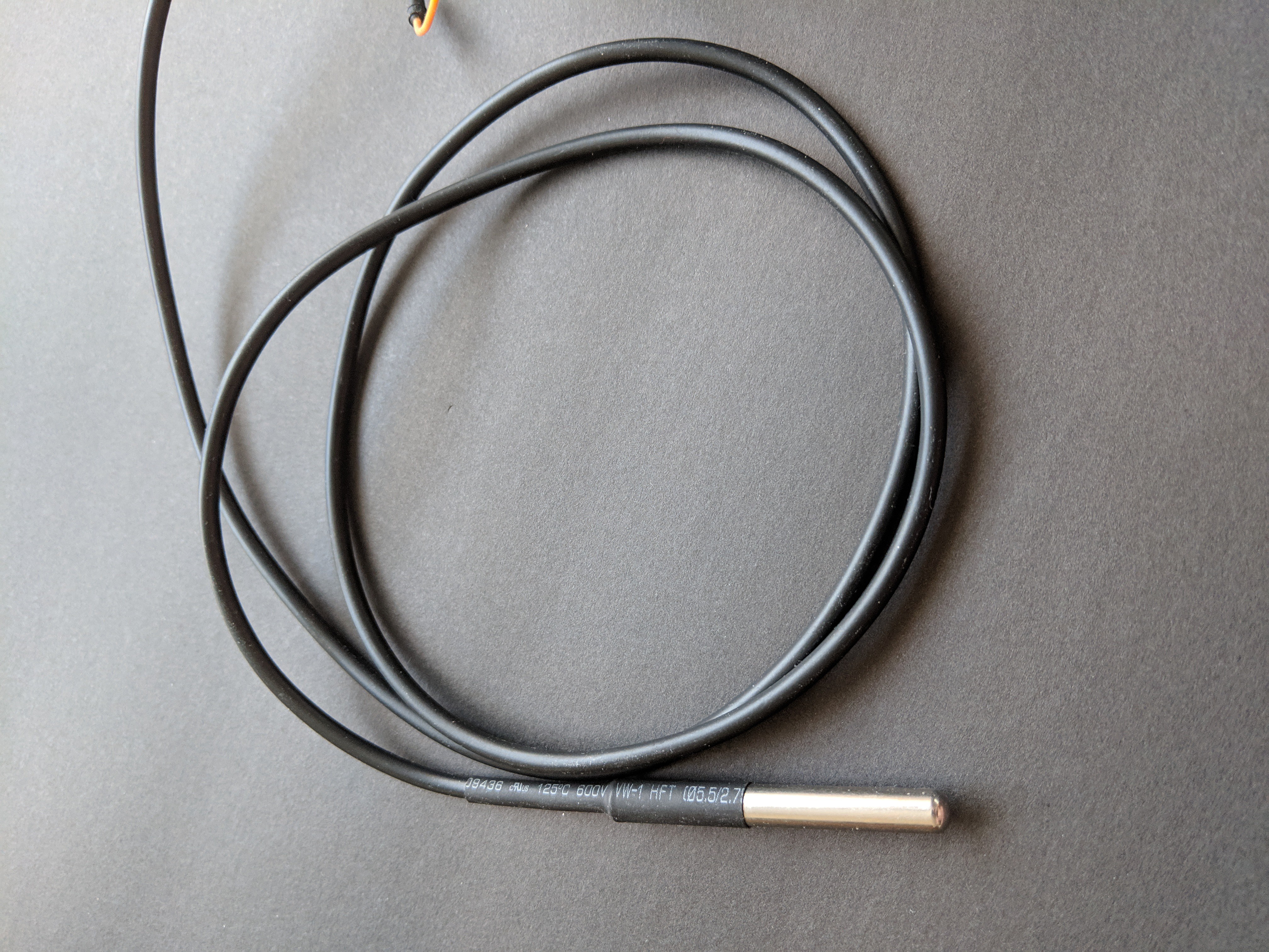
The DS18B20 temperature probe used in this project -
4Wire it up
Included in the repository is an example main.c which utilizes the MQTT library and the 1-Wire library to grab temperature data from an attached sensor and send it to Adafruit IO. If you want to run this code, you will have to edit the files to include your Adafruit username, IO key, MQTT topic name, and your wifi credentials.
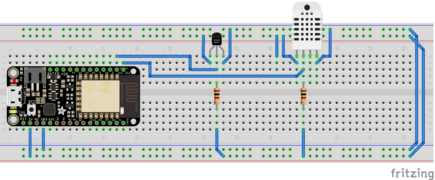
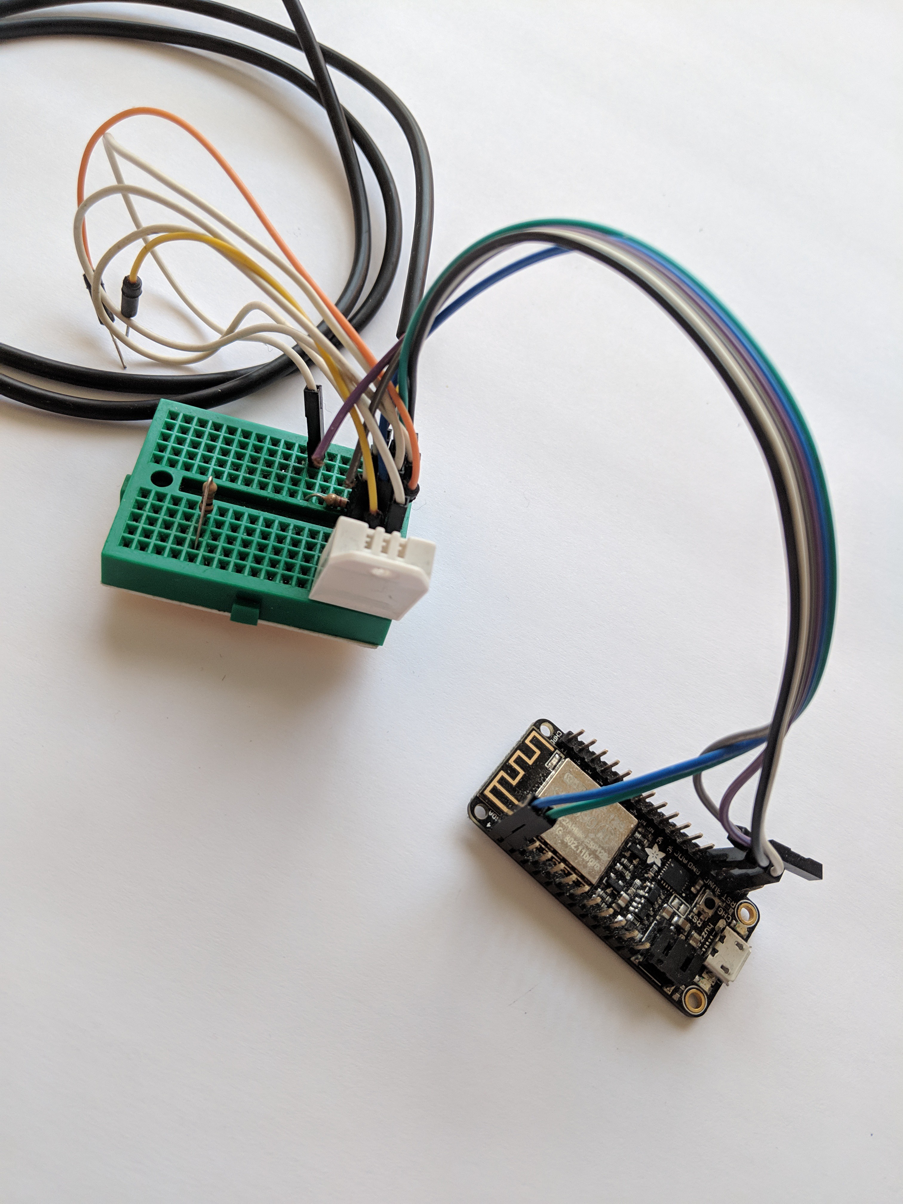
![]()
The above image is from the sister tutorials to this one, but in this version we aren't using the DHT22 sensor (mostly because I couldn't be bothered to write yet another library for this example code), so just ignore it and only connect the DS18B20. The image shows an Adafruit Feather HUZZAH, but any ESP-12F module (or any ESP module which exposes the same pins) will work. As mentioned previously, I highly recommend picking up a development board for the ESP8266 -- it doesn't matter what brand, as long as it has an integrated USB to serial chip and on-board voltage regulator. These are widely available and relatively inexpensive. I like the Adafruit board because it also integrates lithium battery charging circuitry and a JST connector for standard lithium polymer batteries.
Let's take a closer look at the example code. Here's a link to the full file on GitLab. We'll start down at the user_init function and work our way upward.
-
5Analysing the code
As we've established in prior tutorials, every program written with the ESP SDK needs to have a function called user_init(). This function is called by the SDK once it has finished the boot process. Much of the code in our example revolves around getting our mqtt_session_t variable set up. We create an instance of this struct and then create a pointer to it:
LOCAL mqtt_session_t globalSession;
LOCAL mqtt_session_t *pGlobalSession = &globalSession;
This pointer, pGlobalSession, will be used from this point onward. We'll skip down to the variables used to initialize this struct and come back to the code in between afterward. We need to provide all the information used to establish the MQTT connection: the username, password (in our case the Adafruit IO key), IP address of the server, the client ID, and the topic name. Because of the idiosyncrasies of the SDK, it is much easier to store these strings as arrays of ASCII-encoded hexadecimal numbers. This would be a pain to do by hand, so I've written a small Python script to automate the creation of these variables.
It's called strtoarr.py. It's written in Python 3, so make sure you call python3 specifically:
![]()
The first argument is the string you want to encode, and the second argument is the name you want to give to the variable. It will spit out C code which you can copy and paste directly into your main.c. Use this to encode all the variables you need, and then paste them in. After this section, we need to use memcpy to copy these values into the struct.
pGlobalSession->username_len = ioUser_len;
pGlobalSession->username = os_zalloc(sizeof(uint8_t) * pGlobalSession->username_len);
os_memcpy(pGlobalSession->username, ioUser, pGlobalSession->username_len);
First we copy the length to the respective _len variable. Then we use the built-in os_zalloc function to allocate memory that is the correct size. os_zalloc() also zeroes out this area, just in case. Then we use the built-in os_memcpy() to copy the encoded username into the allocated memory.
Once this has been repeated for each of the 5 parameters (notice the IP address can be copied directly - it is always the same length so its memory is allocated statically) the mqtt_session_t is ready to go.
Let's loop back to the rest of the code in between:
char ssid[32] = "yourwifissid";
char passkey[64] = "yourwifipass";
struct station_config stationConf;
gpio_init(); // init gpio so we can use the LED
uart_div_modify(0, UART_CLK_FREQ / 115200); // set UART to 115200
wifi_status_led_install(0, PERIPHS_IO_MUX_GPIO0_U, FUNC_GPIO0); // set GPIO0 as status LED
stationConf.bssid_set = 0;
os_memcpy(&stationConf.ssid, ssid, 32); // copy the ssid and passkey into the station_config struct
os_memcpy(&stationConf.password, passkey, 64);
wifi_set_opmode_current(0x01); //station mode
wifi_station_set_config_current(&stationConf); // tell it about our config, this auto-connects us as well
You need to edit the ssid and passkey variables to your wifi SSID and password. We call gpio_init() because the GPIO will be used for not only the wifi status LED, but also the 1-Wire bus. The uart_div_modify() line is a tip I picked up recently, which allows us to change the UART speed to something much easier to use. With this line of code, we can now output text directly over the USB to serial chip on-board the Feather! This is much better than using an external UART decoder (such as the Bus Pirate I was using previously). The only downside is that all the debug information printed after bootup (such as the firmware version, etc) is still sent at the strange baud rate of 78800.
The rest of the code is just setting up the wifi parameters and setting up the status LED. When we called wifi_station_set_config_current() with the stationConf struct that we copied the wifi info into, this automatically starts the wifi connection for us.
Now let's take a look at the timers at the bottom of user_init(). I find using timers to be the easiest way to run code on the ESP8266. Alternatively, we could use tasks (and we may in the future) but timers are much easier to set up and configure. They also have the benefit of assuring that the hardware watchdog timer doesn't reset, as in between the timer calls there is plenty of time for the SDK to do its housekeeping tasks.
os_timer_setfn(&tcpTimer, (os_timer_func_t *)tcpConnect, pGlobalSession);
os_timer_arm(&tcpTimer, 12000, 0);
os_timer_setfn(&pingTimer, (os_timer_func_t *)con, pGlobalSession);
os_timer_arm(&pingTimer, 16000, 0);
os_timer_setfn(&pubTimer, (os_timer_func_t *)dataLog, pGlobalSession);
os_timer_arm(&pubTimer, 20000, 1);
We have three timers in this example. The first timer waits 12 seconds before firing. It is a single-shot timer, meaning it will only fire once. It calls tcpConnect with pGlobalSession passed as an argument. This function establishes the TCP connection to the MQTT broker for us. This function checks to make sure the wifi is alive, and will set its own timer up to try again if the wifi isn't working after 12 seconds. After 16 seconds, we assume that the TCP connection is established and call the function con(). This function establishes the MQTT session. After 20 seconds, we start the automatic timer which does the datalogging, dataLog(). This is the only timer which is continuous, i.e. it will automatically fire every 20 seconds.
Let's take a look at that con() function:
LOCAL void ICACHE_FLASH_ATTR con(void *arg) {
  os_printf("Entered con!\n");
  mqtt_session_t *pSession = (mqtt_session_t *)arg;
  mqtt_send(pSession, NULL, 0, MQTT_MSG_TYPE_CONNECT);

  os_timer_disarm(&pingTimer);
  os_timer_setfn(&pingTimer, (os_timer_func_t *)ping, arg);
  os_timer_arm(&pingTimer, 1000, 0);
}
This is how the user is expected to write the MQTT-related functions. You must organize the data or command you want to send, and then call mqtt_send() with a pointer to the active MQTT session, as well as the message type you want to send, and optionally the data and data length to be sent in the case of PUBLISH. Afterwards, you need to set a timer to periodically send the MQTT PINGREQ message. If you don't ping, the server will terminate the connection, assuming the client has lost connection. The amount of time it waits is configurable, but it's best practice to have a ping timer anyway.
You'll notice that all the functions called by timers take void *arg as their only argument. This is because the timer setup function allows us to pass an arbitrary pointer to the function called by the timer. This is extremely useful, as the function needs the pointer to the active MQTT session in order to work. Because it is a pointer to void, we must first cast it to the correct pointer type for it to be useful. Thus, the first line in all these example user functions is the creation of a pointer to mqtt_session_t as well as casting arg to that type.
The studious among you who take a look at mqtt.c will see a similar pattern with the callback functions in there. However, they have an extra trick up their sleeve: those functions are passed a pointer to the espconn struct, which is a type defined by the SDK. This struct contains information about the TCP connection. The problem is these functions also need a pointer to the mqtt_session_t in order to implement user callbacks in the future. The solution? The espconn struct type has a pointer to void inside it, intended by the Espressif devs for exactly this type of situation. It is called reverse and you might notice that after casting arg to espconn, we then cast reverse to mqtt_session_t! Talk about making your head spin.
-
6Logging data to Adafruit IO
Now that everything is all set up and running, the dataLog() function will be called every 20 seconds. This function simply tells the DS18B20 to make a temperature measurement, and then grabs that measurement. It subsequently sends that data off to Adafruit IO via the pubfloat() function. Let's take a look:
LOCAL void ICACHE_FLASH_ATTR pubfloat(void *arg) {
  os_printf("Entered pubfloat!\n");
  mqtt_session_t *pSession = (mqtt_session_t *)arg;
  float *data = (float *)(pSession->userData);
  char *dataStr = os_zalloc(20 * sizeof(char));
  ftoa(*data, dataStr, 2);
  int32_t dataLen = os_strlen(dataStr);
  os_printf("Encoded string: %s\tString length: %d\n", dataStr, dataLen);
  mqtt_send(pSession, (uint8_t *)dataStr, dataLen, MQTT_MSG_TYPE_PUBLISH);
  os_timer_disarm(&pingTimer);
  os_timer_setfn(&pingTimer, (os_timer_func_t *)ping, arg);
  os_timer_arm(&pingTimer, 1000, 0);
}

LOCAL void ICACHE_FLASH_ATTR dataLog(void *arg) {
  mqtt_session_t *pSession = (mqtt_session_t *)arg;
  oneWire_t DS18;
  oneWire_t *pDS18 = &DS18;
  uint16_t temp = 0;
  sint32 time = 0;
  pDS18->temperature = 0;
  reset();
  transact(pDS18, SKIP_ROM);
  transact(pDS18, CONVERT_T);
  time = system_get_time() + 750000;
  while(system_get_time() < time);
  reset();
  transact(pDS18, SKIP_ROM);
  transact(pDS18, SCRATCH_READ);
  //os_printf("\nReceived onewire data: %x %x\n", pDS18->scratchpad[0], pDS18->scratchpad[1]);
  temp = ((uint16_t)pDS18->scratchpad[1] << 8) | pDS18->scratchpad[0];
  pDS18->temperature += (temp >> 4) + ((temp & 0x0F) * 0.0625);
  pSession->userData = (void *)&pDS18->temperature;
  os_printf("\nTemperature is: %d.%02d\n", (int)pDS18->temperature, (int)(pDS18->temperature * 100) % 100);
  pubfloat(pSession); // publish the temperature
}
Looking first at the dataLog() function, we can see that it calls two functions from the 1-Wire library: reset() and transact(). Calling reset() simply issues a reset condition on the 1-Wire bus. Transact takes a pointer to a oneWire_t variable as well as the 1-Wire message to send. The possible messages are enumerated in onewire.h. After issuing CONVERT_T, we wait 750000us (750ms) for the conversion to complete. We then send another reset(), and then read the scratchpad with SCRATCH_READ.
The temperature data is split into two 8-bit registers, scratchpad[0] is the lower 8 bits, and scratchpad[1] are the higher 8 bits. We combine these into a 16-bit variable called temp, and then we convert this into a floating point number which is then stored in the temperature member of the pDS18 struct (which is of type oneWire_t).
![]()
The circuit, fully prototyped! This is fairly simple, as the top 12 bits are the integer portion, and the bottom 4 bits are the mantissa. The mantissa is not a direct representation, instead it is a count of how many 0.0625 there are after the decimal point. So, we multiple the mantissa portion by 0.0625 and add this on. For more information, definitely check out the DS18B20 datasheet. This value gets stored into the user_data field of the mqtt_session_t. Then we call pubfloat().
I separated the actual publishing portion into its own function to make the code a bit easier to read. It's fairly self-explanatory. It just takes the data, converts it from a floating-point number into a string, and then passes it to mqtt_send as a PUBLISH message. Afterward the ping timer is re-enabled.
Once you've made the requisite changes to the code, programming it just as easy as before. Simply go to the project folder, and run:
$ make flashIf needed, change the port name in the Makefile to whatever port your board is connected to. Back in Part 1 I showed how to make a udev rule so your board will always show up with the same name, no matter which USB port it is plugged into. I named mine /dev/feather0 and so I've stuck with that naming scheme here.
If you encounter any build errors, check the Getting Help section in the details!
-
7Final thoughts
I know this project is a steep jump in complexity from Part 2, but in order to get real-world projects done in C, this is typically the type of code you will see. If you're unfamiliar with C, or you are confused by something, just check the Getting Help section in the details of this project. There are a few different ways you can contact me. You can also leave a comment here if you spot a mistake, and I will endeavour to fix it as quickly as possible!
Don't be intimidated. If you get frustrated, just take a few minutes to watch cat videos on YouTube and then try again. Persistence is key when learning how to code, especially when you are in the difficult portion of the learning curve.
Now that we've learned more about using the SDK, next time we will be taking things to a full-scale project. Stay tuned!
ESP8266 SDK Tutorial, Part 3
Our first IoT project using MQTT and the SDK!

Discussions
Become a Hackaday.io Member
Create an account to leave a comment. Already have an account? Log In.