Ronni Bantz
-
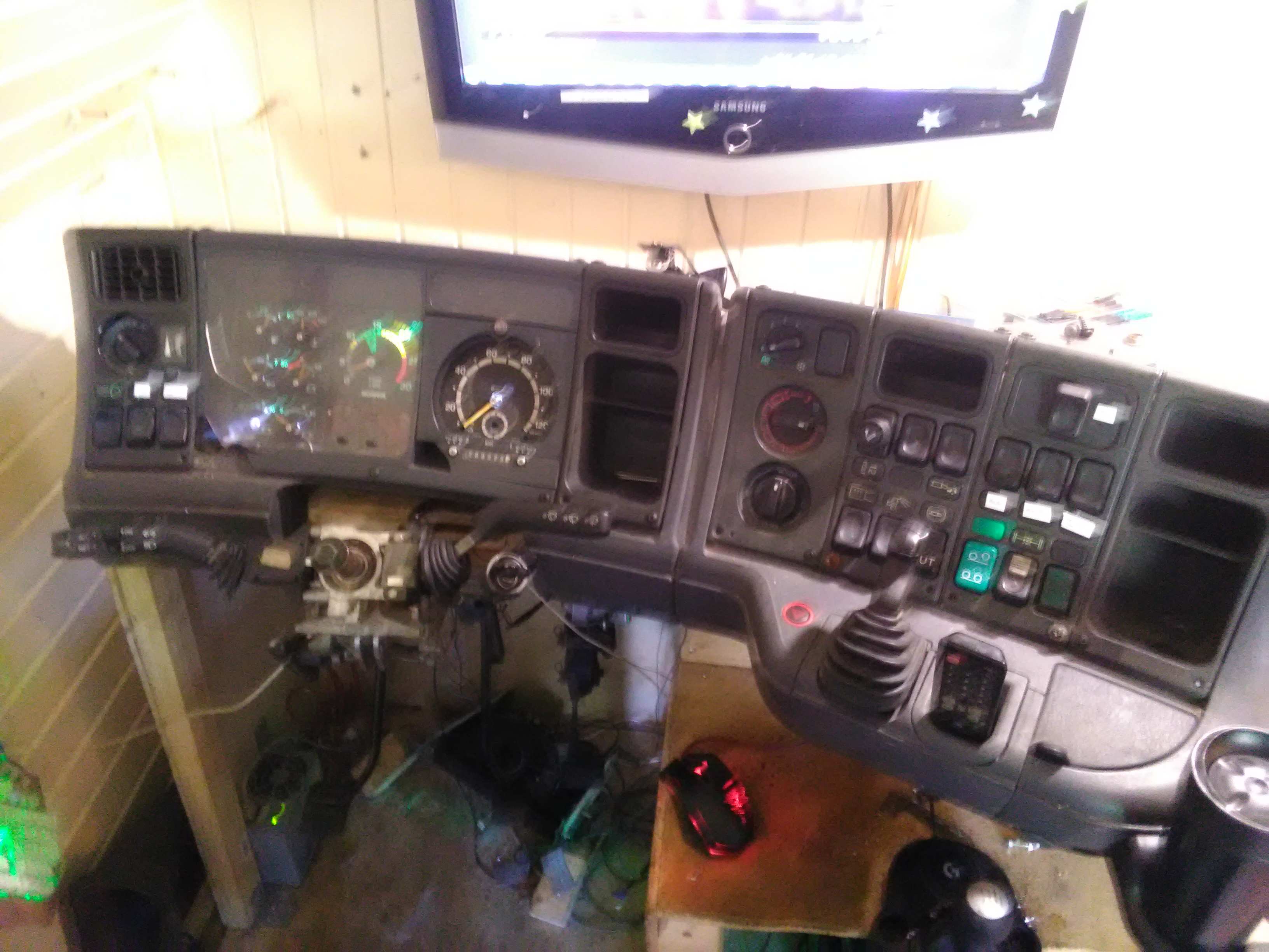
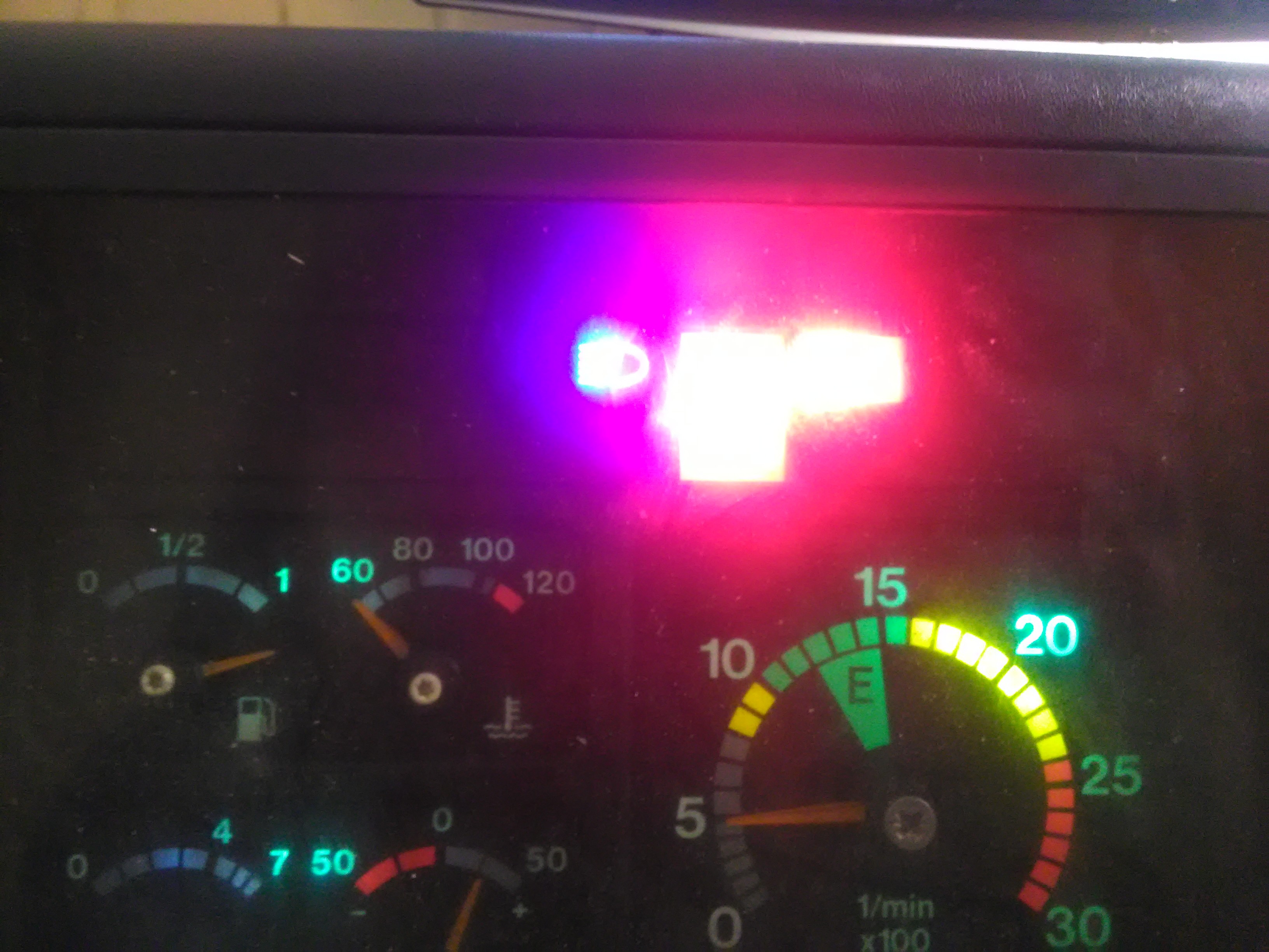
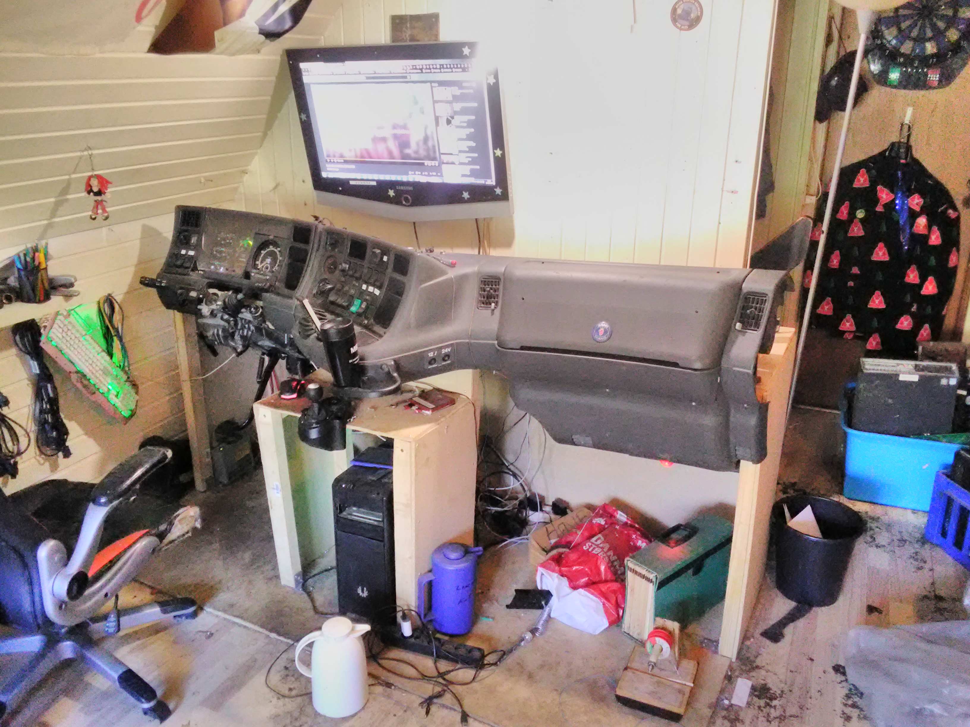
Almost Completed
05/26/2019 at 18:06 • 0 comments![]()
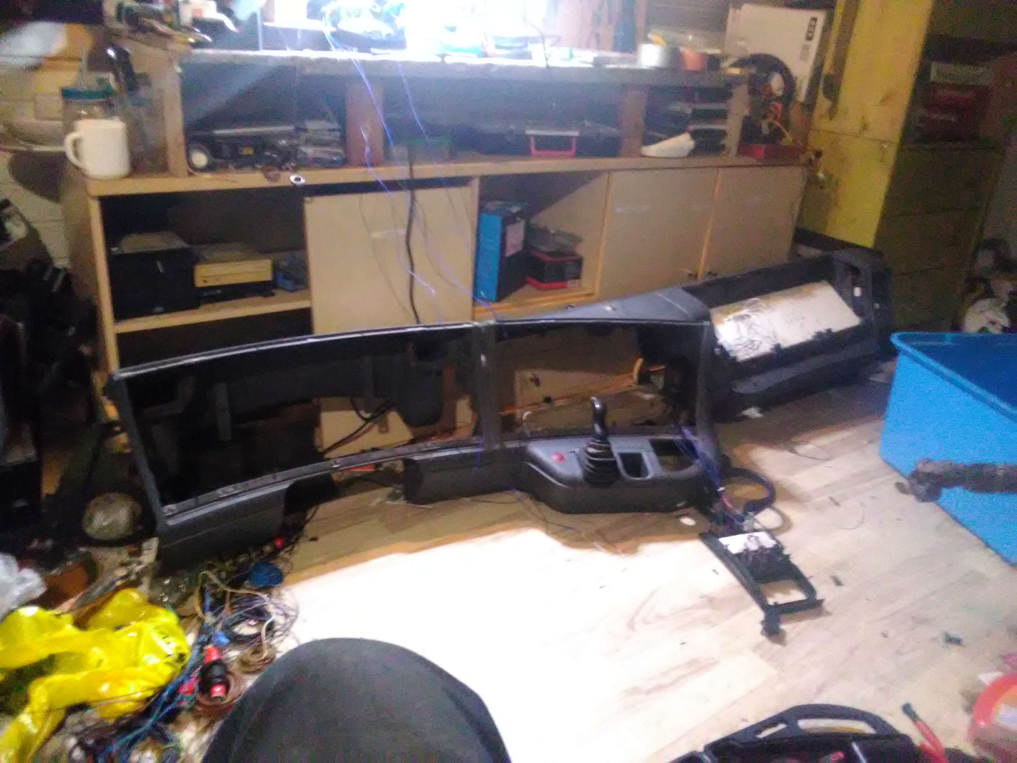
There is not much left to do on the project :) all instruments and buttons are functional.
The things that are left to do is : Sterring, clutch, ignition and getting a SKRS gearnob for the shifter and a scania seat![]()
![]()
-
Frame Building & mounting of the first parts
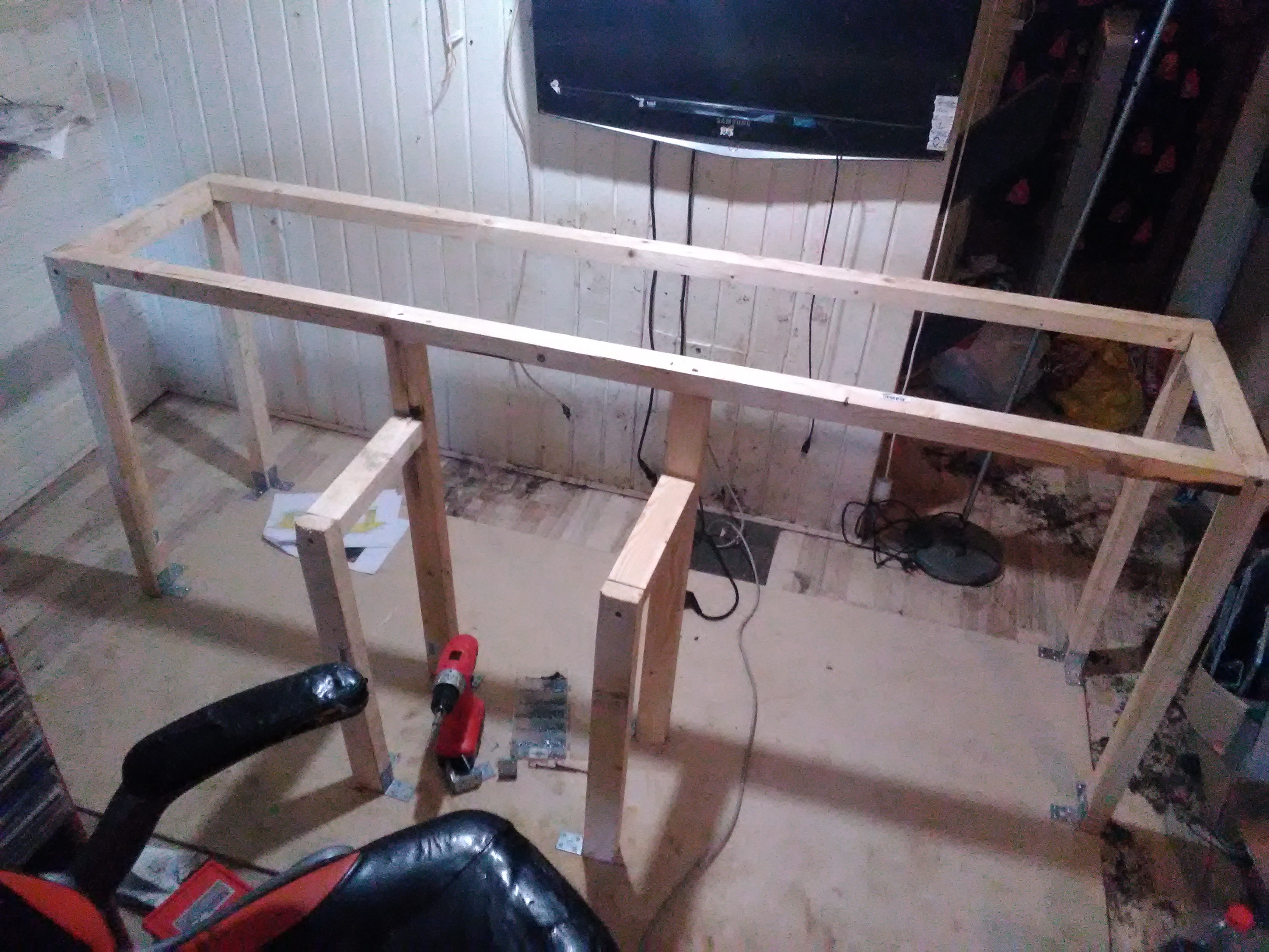
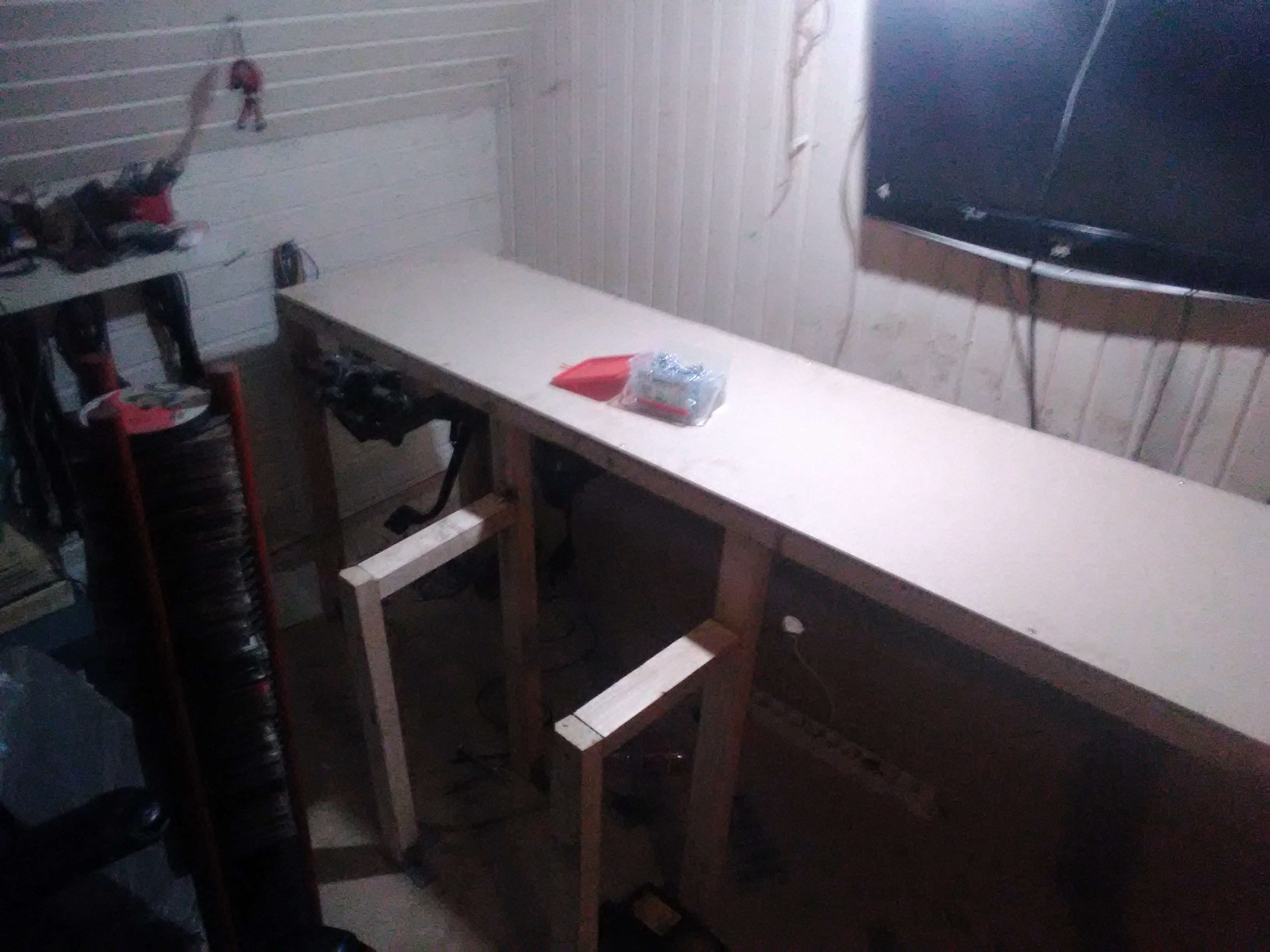
02/06/2019 at 20:48 • 0 commentsSo I finally got the wood I needed to start building the actual frame for the simulator.
For the buttom plate I used a big 1000X2000 cm particle board, the actual framing is made with 38X57 mm lathes.
The vertical lathes is attached to the buttom plate with angle brackets, then it was just a matter of filling in the gabs between them with the horizontal lathes making a square box to mount the parts on.
![]()
Then I started covering the frame with pices it partickel board , very simpel just cut to size with a jigsaw and screwed on to the lathes.
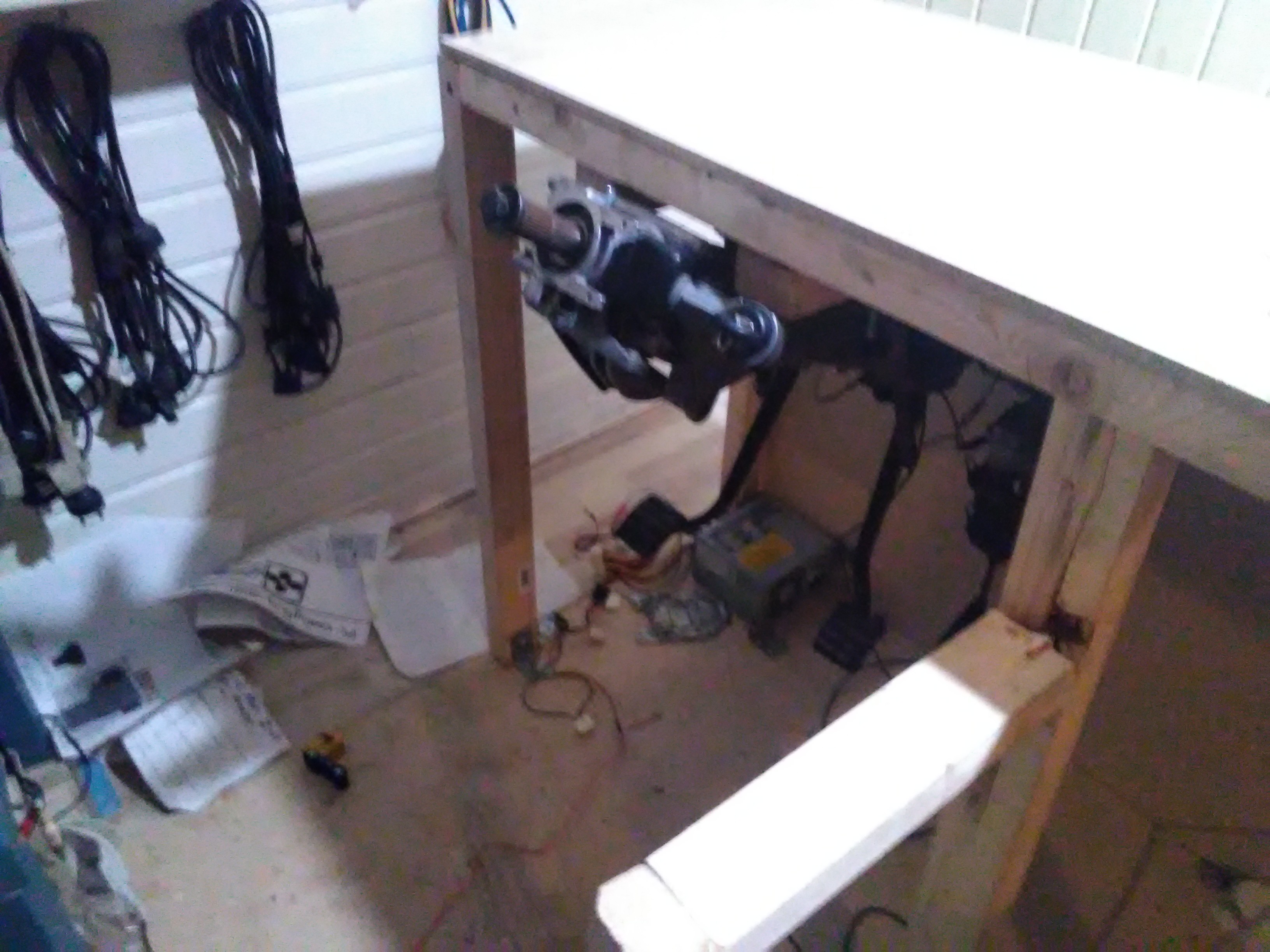
I then mounted the steering bracket / pedal assembly on to the frame, this was done using the original Scania mounting bracket by drilling holes in the lathes and screwing it all together with some big bolts I had leftover from a mailbox
![]()
![]()
-
Finished the prepping of the dash
01/26/2019 at 02:31 • 0 comments![]()
Finaly the prepping of the dashboard is complete :) Everything is solderet and connectet to the circuitboards. So now i am just wating on the wood i have orderd to build the frame :)
-
Prepping The dashboard
01/02/2019 at 16:35 • 0 comments![]()
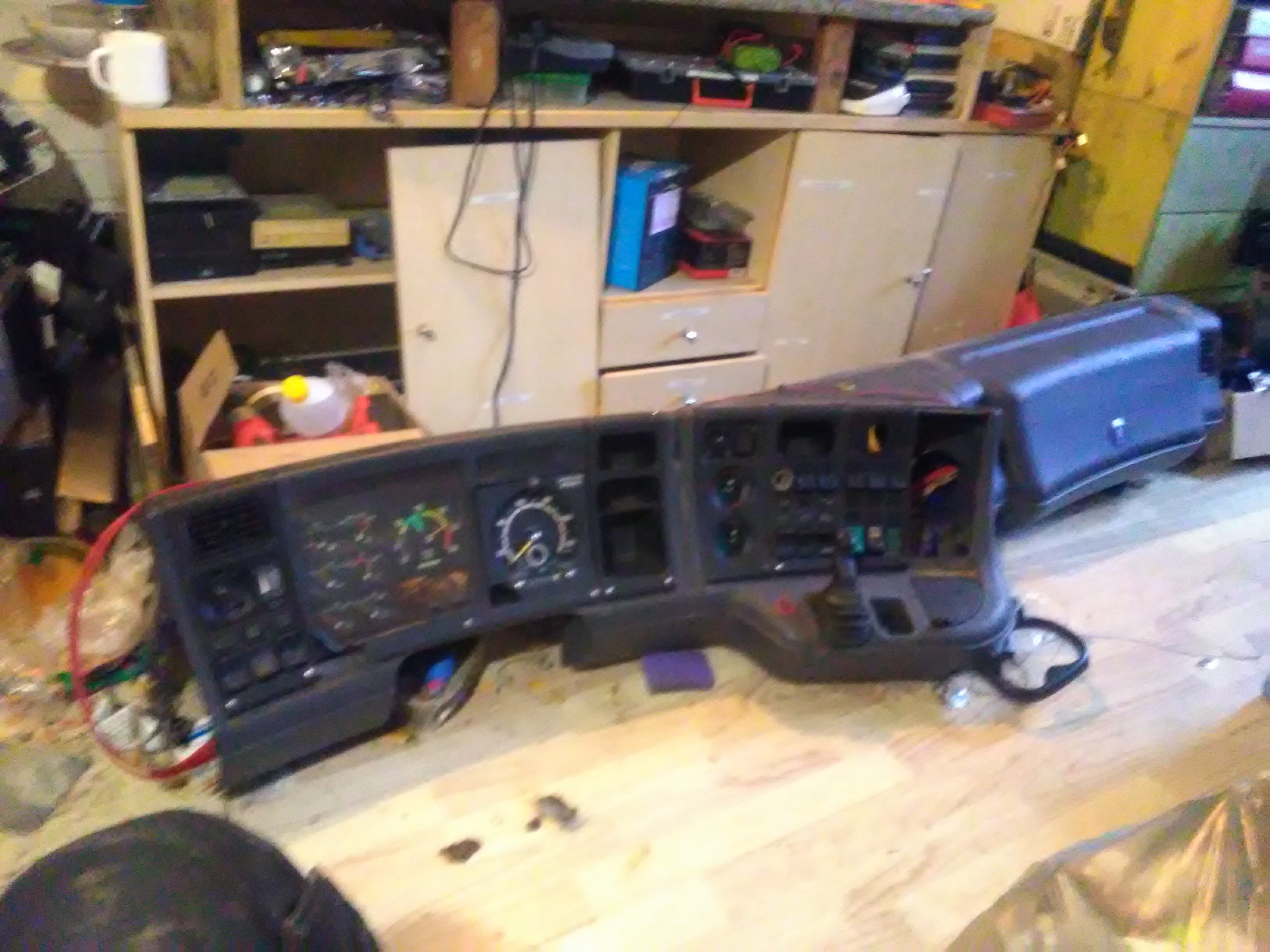
Finaly i got a hold of the dashboard, so now the project countinus :)
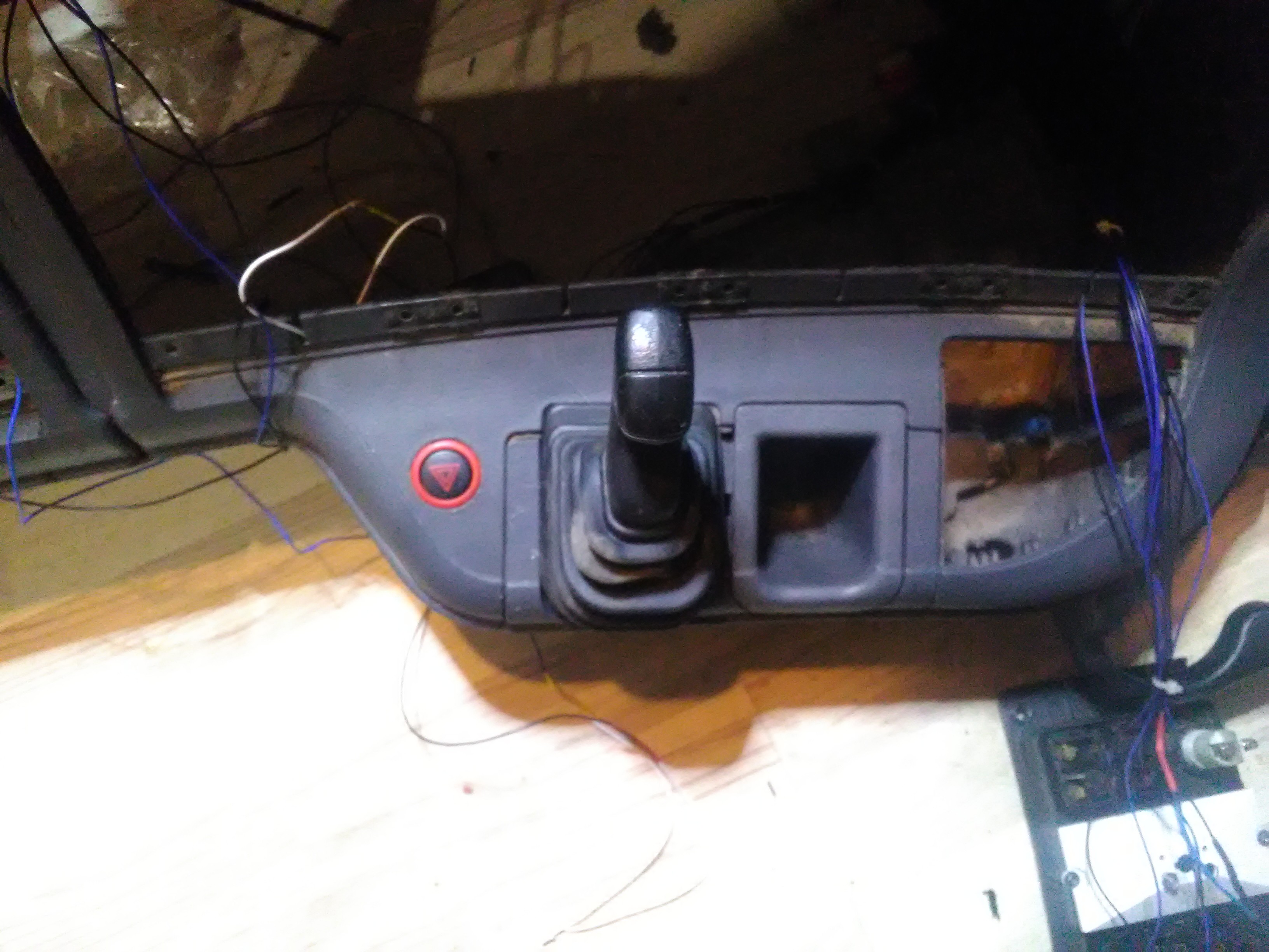
Started with unscrewing the handbrake (From underneath you unscrew the big monunting bracket ) and disasembling the handbrake. Got rid of moste of the parts and kept only the top.
I then screwed a srew in to the bottum of the handle so there was somthing to activate the microswitche.
I screwed som wood on to the big mounting bracket to have somthing to mount the microswiches to.
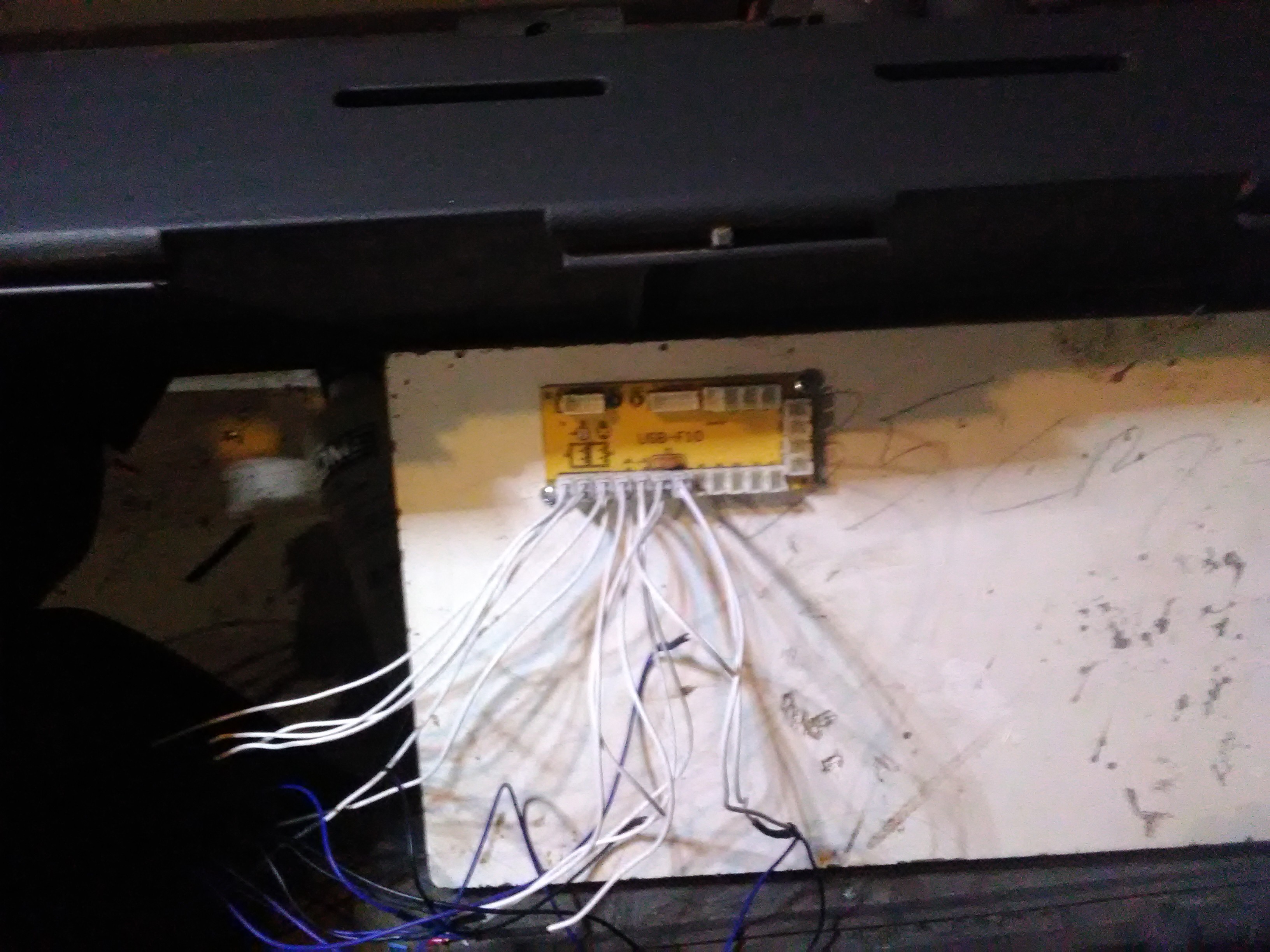
Then i mounted the handbreake handle back onto the bracket, alligend the 2 microswitche and mounted them on to the wood,. an put the hole thing back onto the dashboard and wired the microswitche and the emergency blink kontakt to the Zero Delay Usb Encoder that i have mounted in the glowbox on a pice of plywood.
Now it is just a matter of soldering the rest of the contactpanels and the cluster and wire them to the usb encoders and arduino
![]()
![]()
-
Testing the rev-counter is working in ets2
12/01/2018 at 19:37 • 0 commentsJust a little test of the newley installed servo's and the arduino programming
-
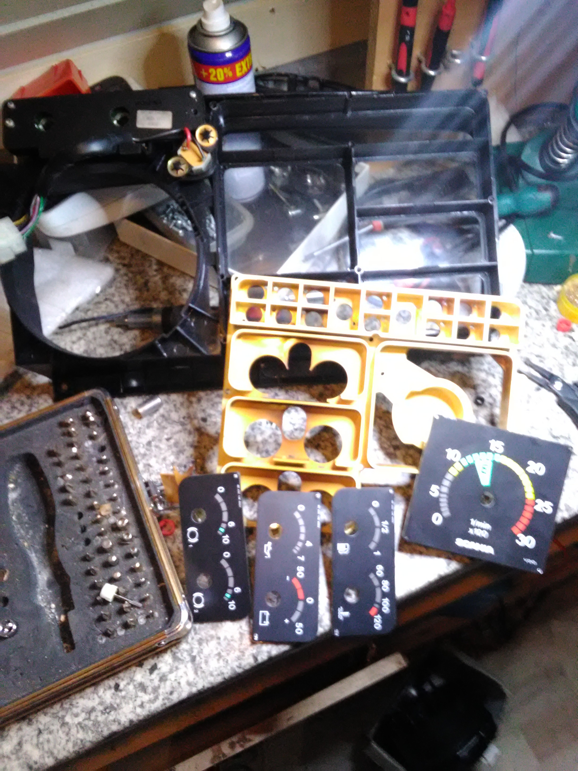
Starting to asemble the cluster
12/01/2018 at 01:31 • 0 comments![]()
![]()
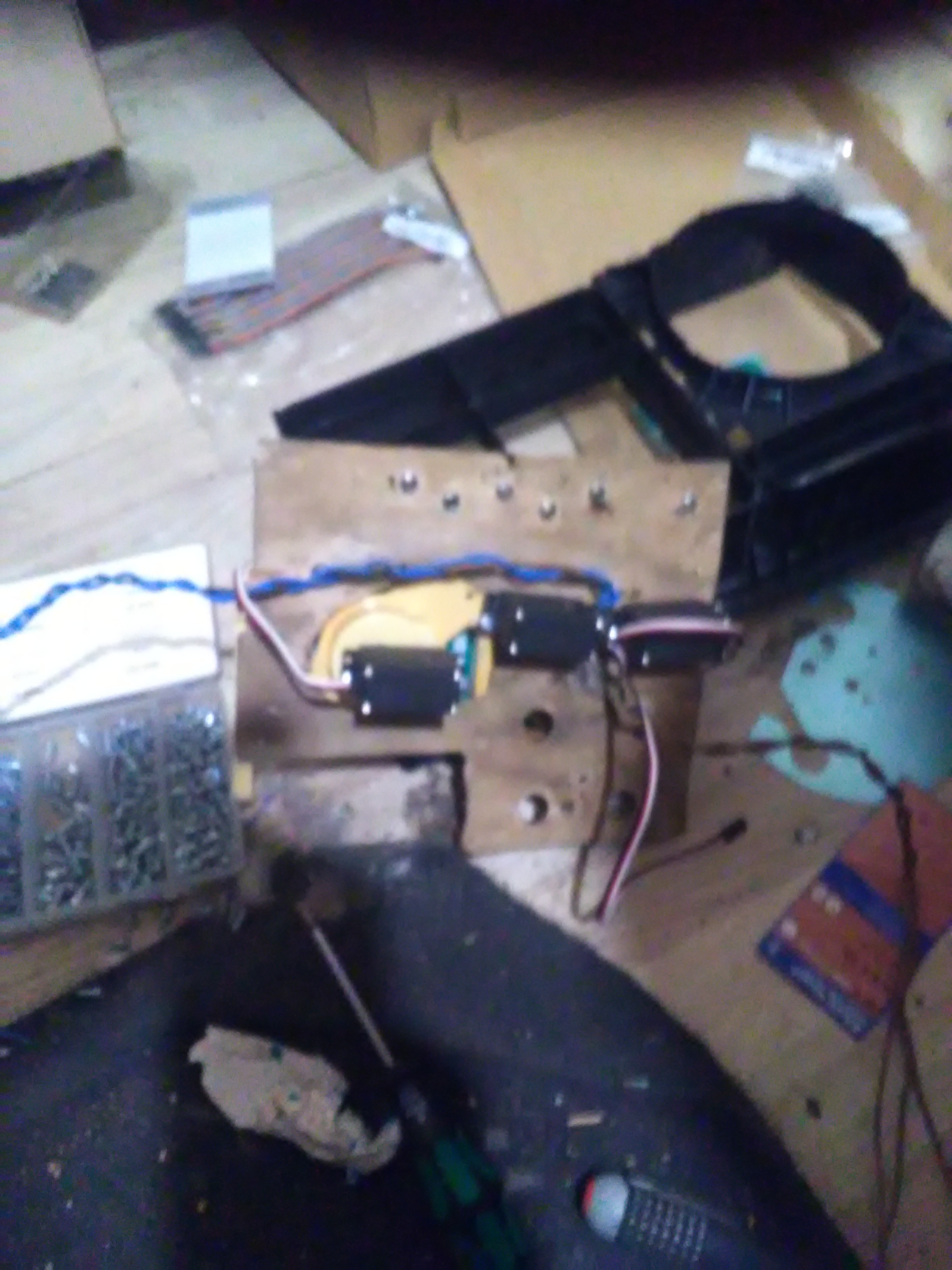
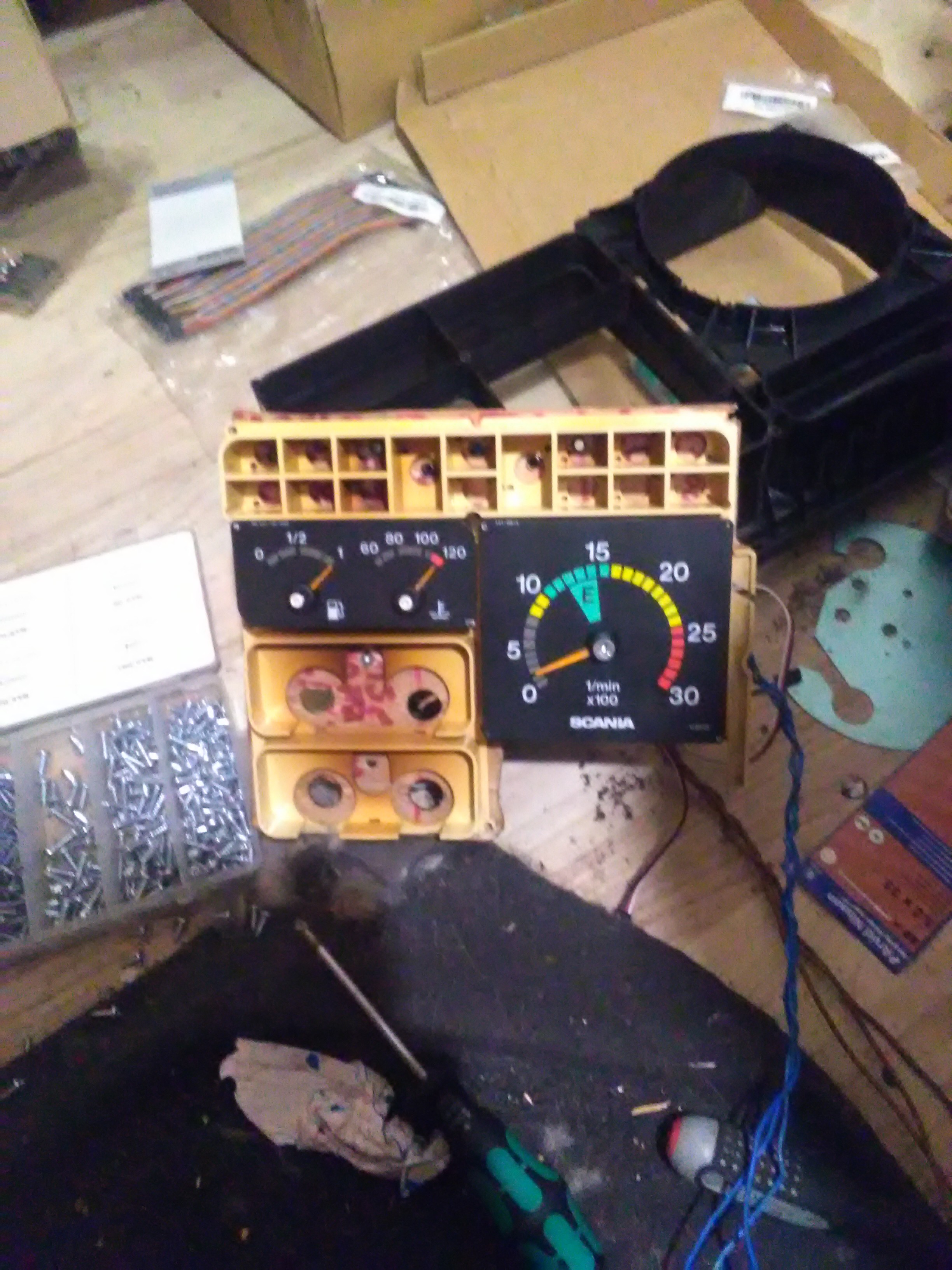
Today i recivede some of the servo's so i thought i would start asembeling the cluster again :)
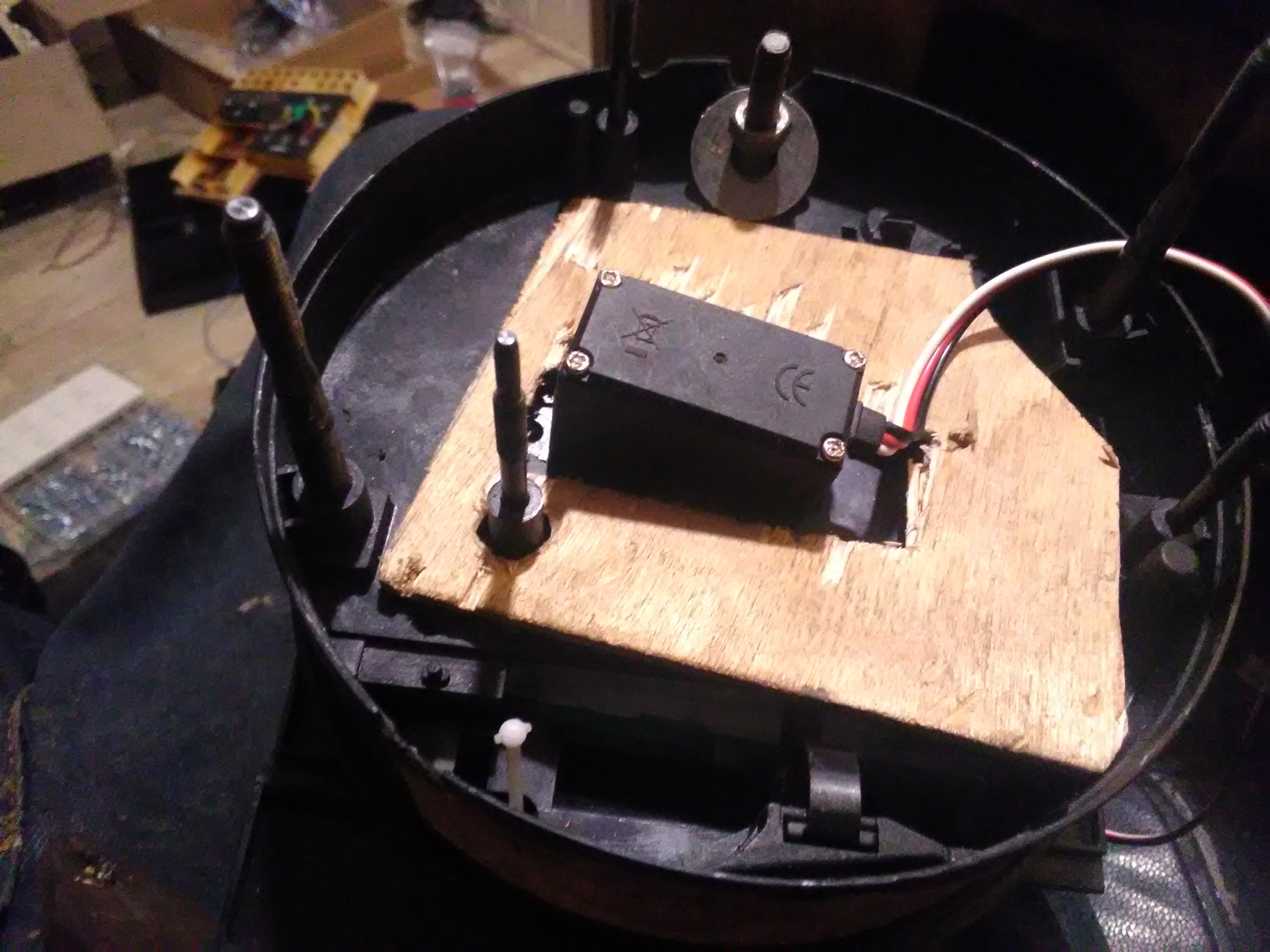
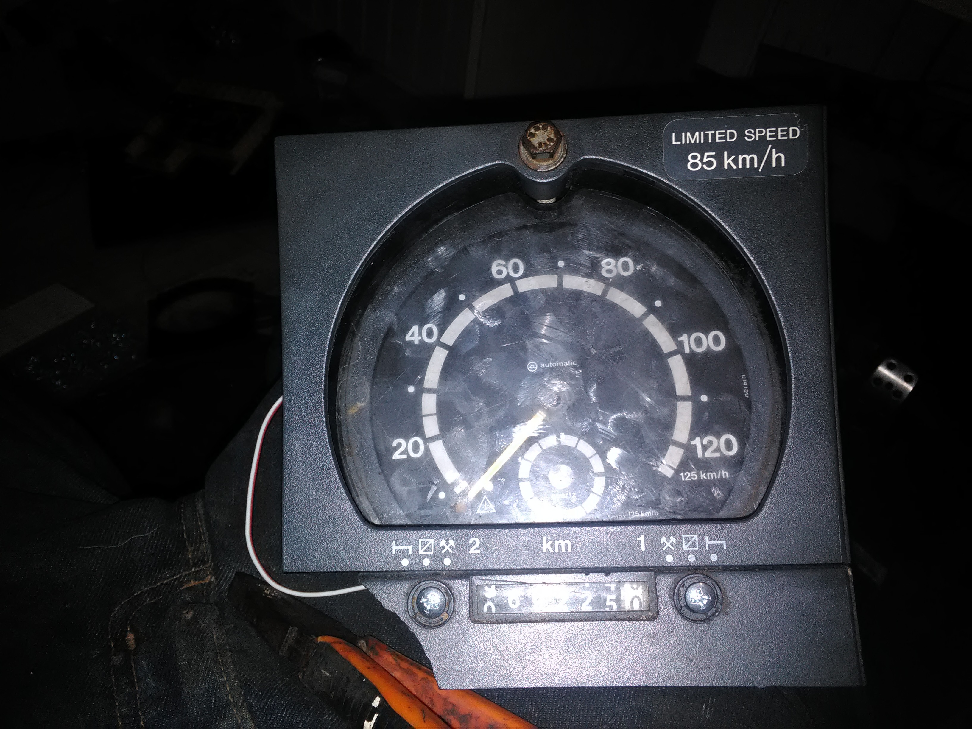
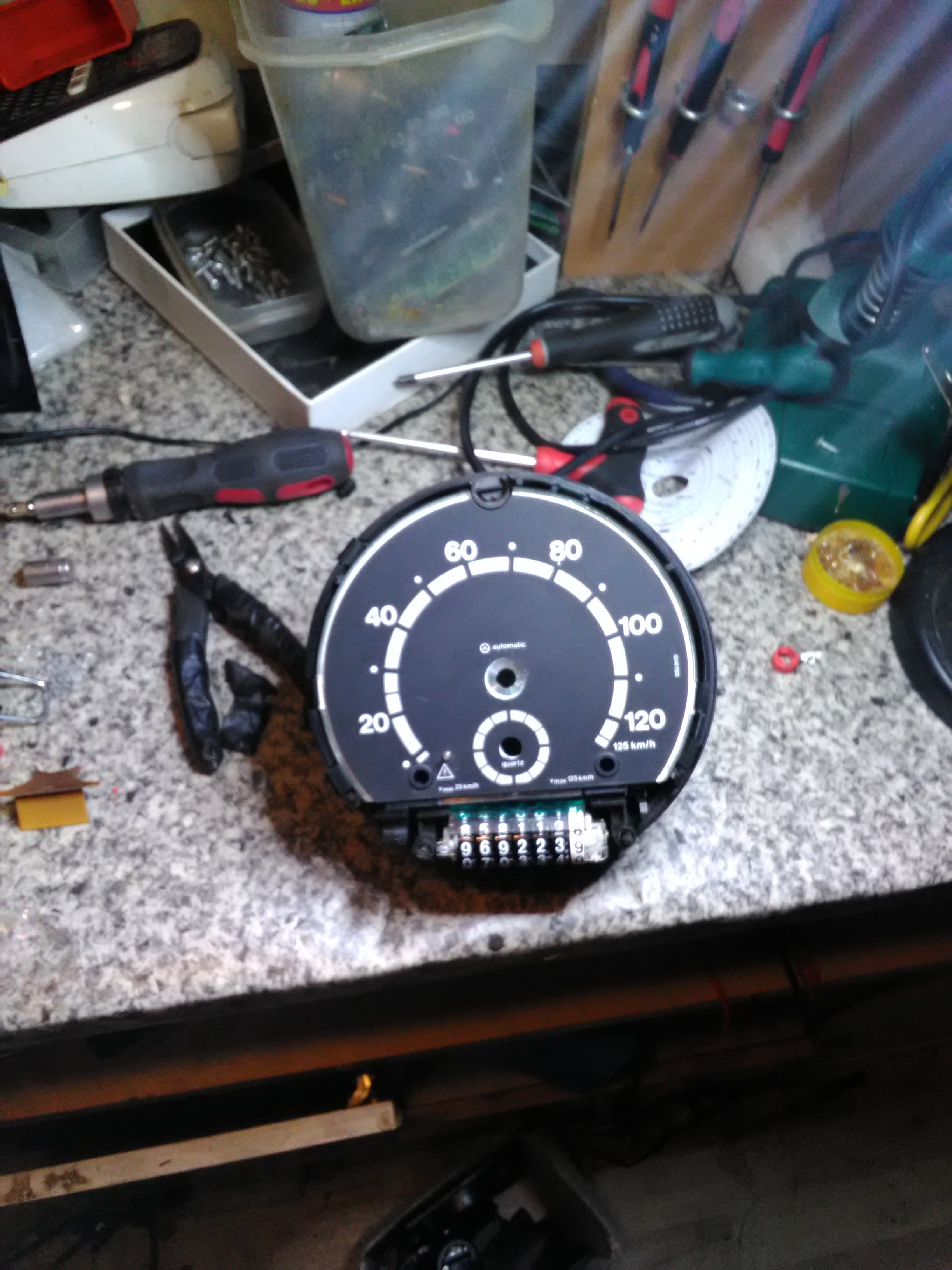
I started out with drilling and grinding a hole in the back of the rpmcounter, and fitted the servo, then i drilled a small hole in the needel and found a screw that was long enough to reach from the needel to the servo.Then i just put the revcounter dial back in place and screwed the needel on to the servo the same thing with the fuel gauge and water temp gauge.
With the speedometer i started out wirh cutting out a hole in the backplate the servo would fit throug, then mounted the servo with a couple of short screws, drilled a small hole in the needle and assembled the hole thing.
I also made a small wooden plate to mount on the backside to mount the background light diode to.
![]()
![]()
-
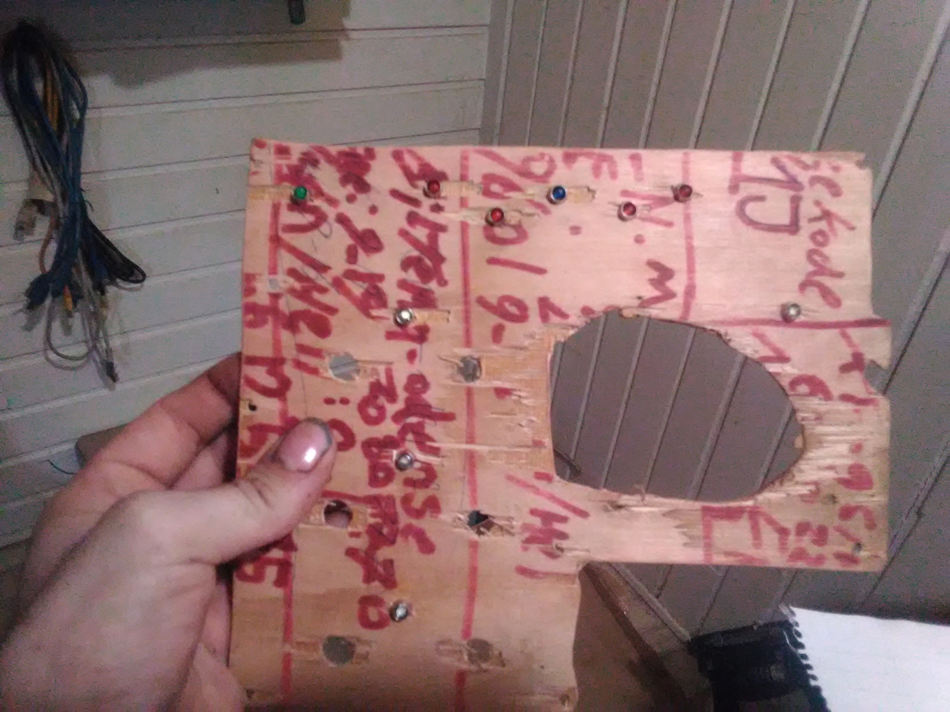
Starting To Prep The Cluster
11/16/2018 at 02:05 • 0 commentsGot some more parts yeastaday (Light diode's, diode mounts an the zero delay usb encoders)so now we move on with prepping the instrument cluster
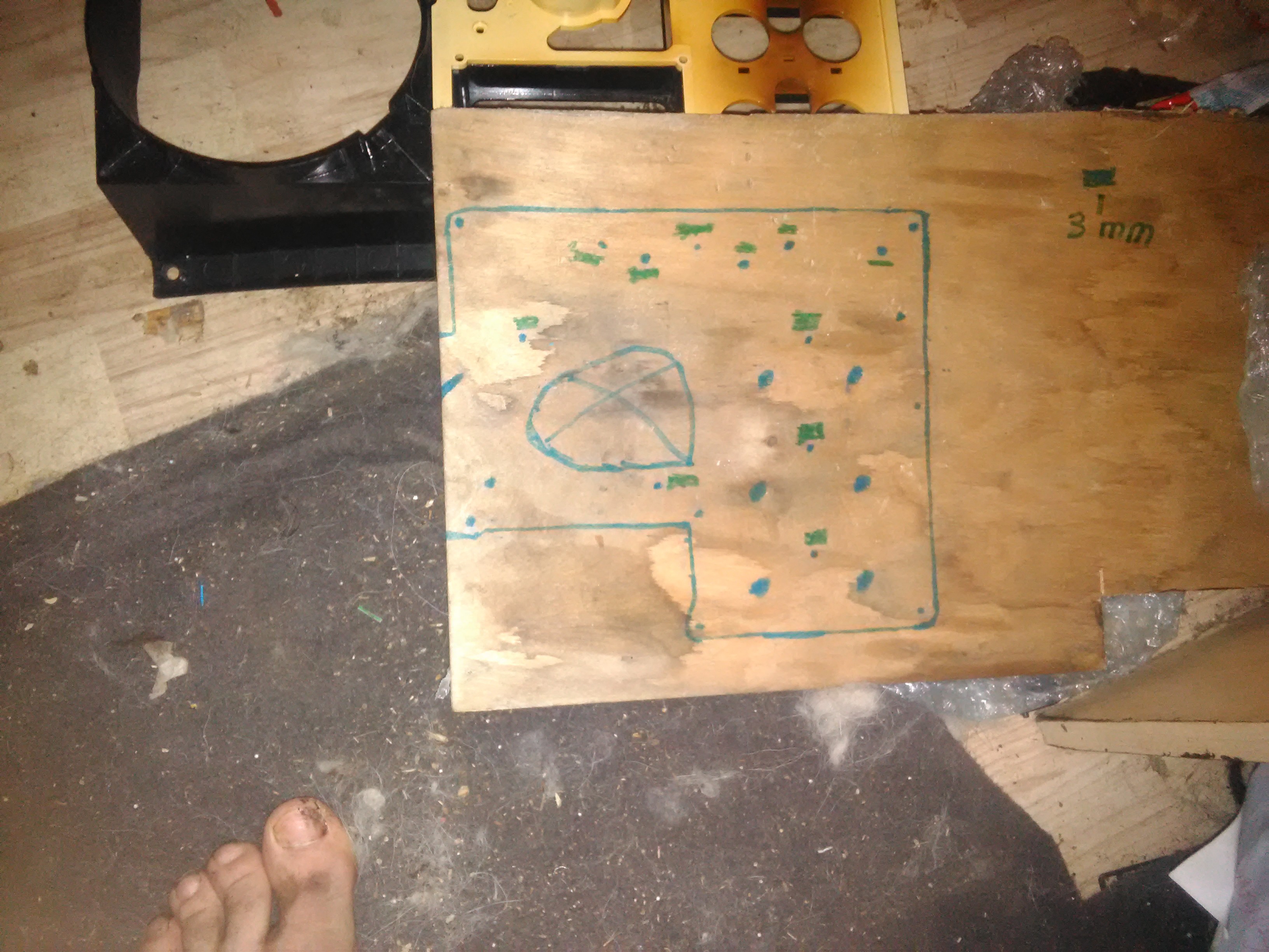
Now we need something to actualy mount the servos and diode mounts to, so i laid a pice of paper over the backside of the cluster an made a paper template of where the diffrent holes should be. I then transferred it to a pice of old thin wooden plate i had laying arround
![]()
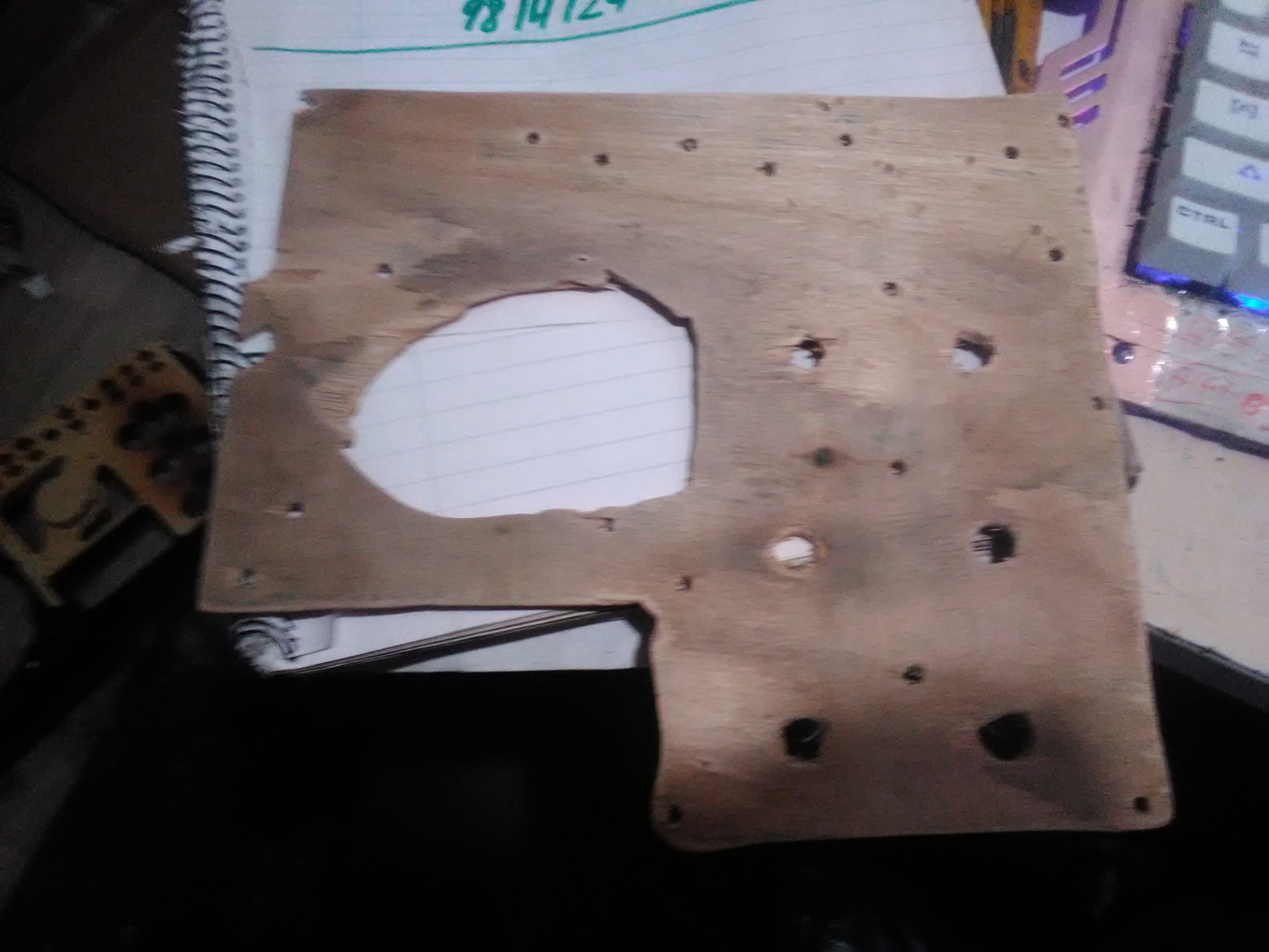
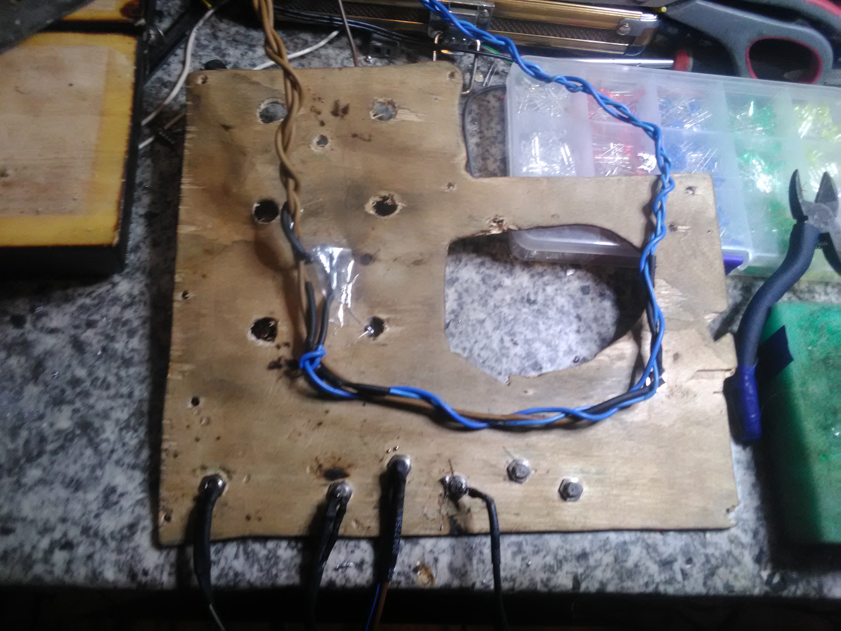
Then it was just a case of grabbing the drill, the Jigsaw and some sandpaper to make the cluster backplate
![]()
When that was done i test fitted the backplate on the cluster to see if everything fit, an fortunately it did :) Then i skrewed the diode mounts in place (Unfortanley i diden't buy quit enough of them) and put the different diode's in the mounts
![]()
![]()
Then i started the soldering work and got a few diode's finished before my soldering iron gave up, here is what it looks like so fare
![]()
So now we are at kind of a stand still until i get a new soldering iron an get some more parts, wich will be around the 1. december. I'm planing on that the next big part i will get is the actual dashboard of a scania 4 series so that we can start building the structure
-
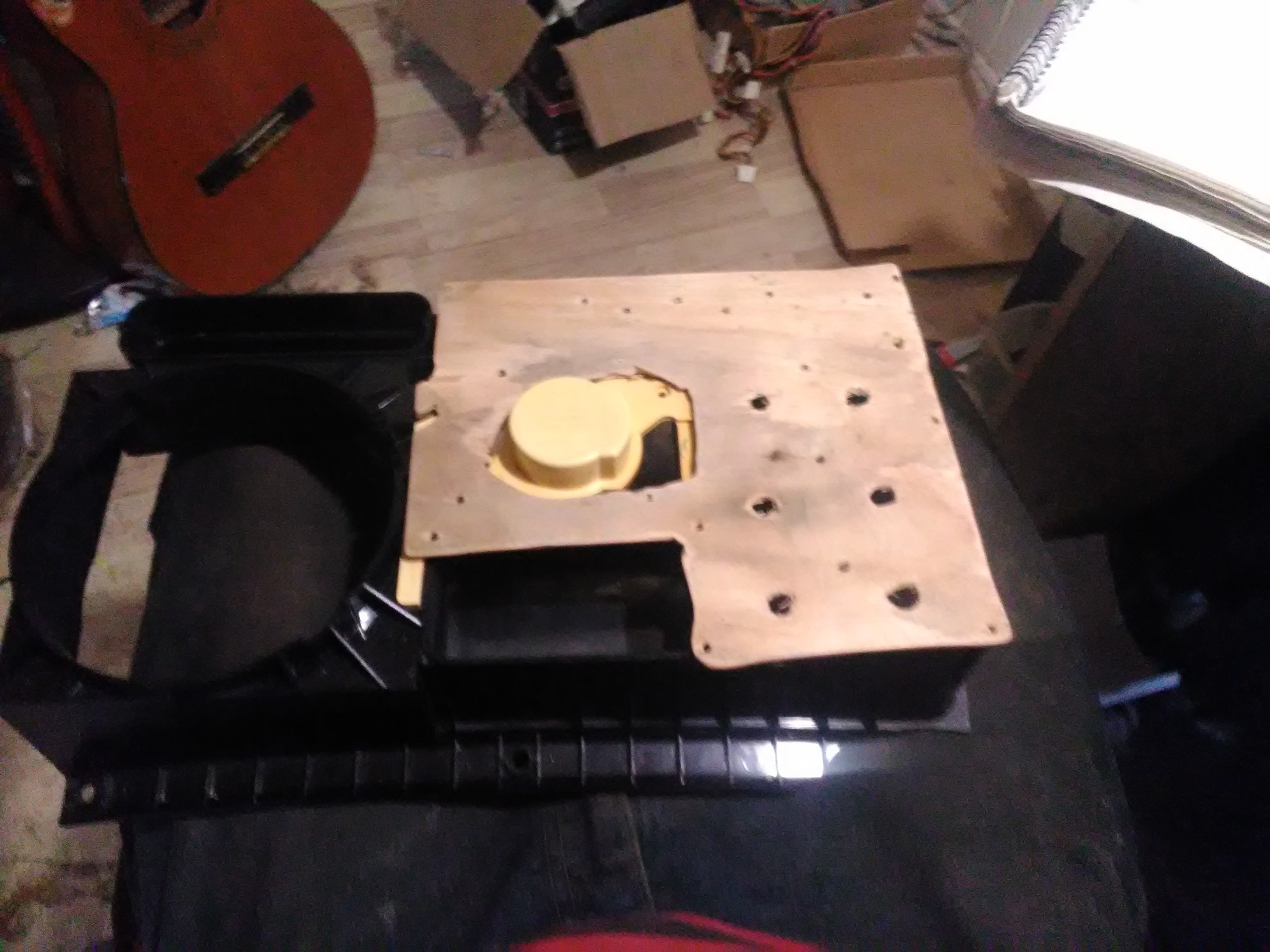
Prepping the first parts
11/13/2018 at 03:43 • 0 comments![]()
![]()
![]()
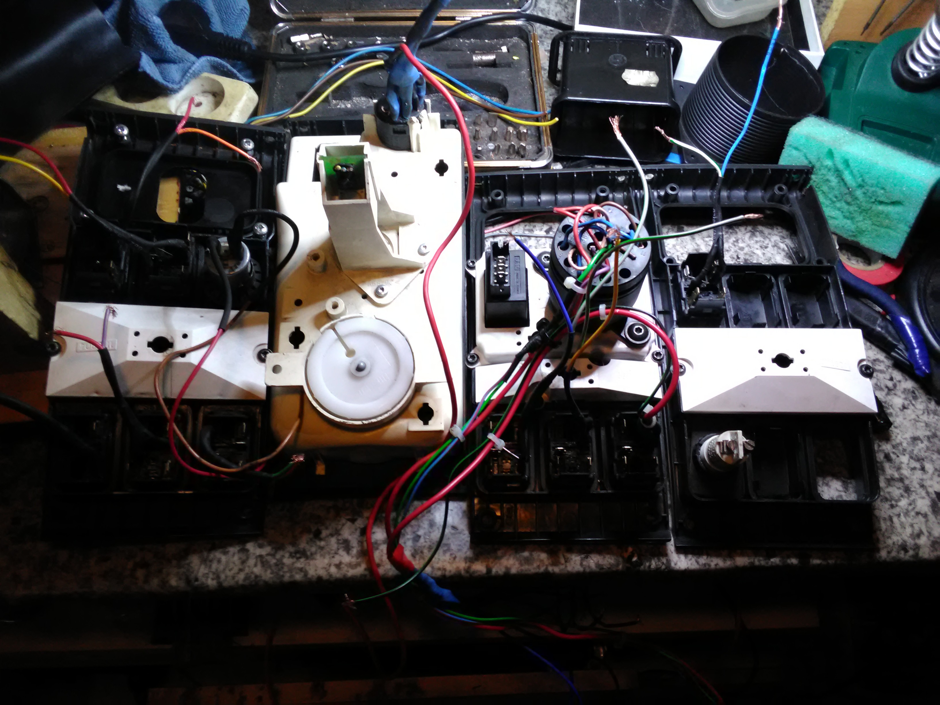
I have now finished prepping all the parts i have so fare.
. The instrument cluster - Disasembled ready for mounting of light diods for the warning lights and servo engines for the dials
. The speedo-drive - disasembled ready for mounting the servo engine
. All the button panels - i have mesured out wich connectors that are connectet on the buttons with a multimeter tool (set on OhM, when it shows 0 ore you hear a biiiiiip sound you got the right connectors) and have solderet wires on these connectors so they are ready to be connected to the zero delay usb encoder
So now im just wating for more parts to arrive
DIY Homemade Scania Truck Simulator
This is my first big project building a homemade truck simulator with real scania 4 series parts