Teardown
I won’t explain. Just YouTube it if you’re having trouble.
There are a few gotchas on the way however.
One, mine has drivers with inverted aluminium domes. Aluminium is SOFT. Combine it all with a freshly undone screw that I’ve failed to catch, and we have dents in the dome. Oops! (see project gallery).
Phew, it was a small screw. Larger ones that hold the drivers will probably make it all the way through, be careful. Drivers from older revisions of Flip 4 seem to be plastic, much more impenetrable.
Another gotcha: it looks like the speakers are connected to PCB with connectors, but these are not connectors, you can’t undo them. The only way to get the pcb out is to desolder the wires from the drivers.
The pcb
Says “FLIP4_MAIN_PV2.0”.
Contains:
· Bluetooth subboard, based on CSR8675 specialized SoC by Qualcomm. It looks like it is possible to reconfigure the firmware. I haven’t found a full datasheet for the chip yet, it’s all horribly proprietary =(
· MX25U3235 15MB SPI flash on BT subboard. There is very little communication going on, makes me wonder what is it being used for.
· Amplifier based on TPA3130 from TI. It’s a fairly powerful stereo class-D amp, capable of up to 15W per channel.
· The amp is powered from a boost converter, that converts single Li-ion cell voltage to 5-11 V. The voltage is dynamically adjusted to match for signal level, probably for improving battery life at low loudness. Boost converter chip is probably MP9428 (says MPHM9428 on the IC itself). The chip looks very similar to MP3428A by Monolithic Power Systems. If that is the chip, it can go up to 22 V, and can potentially give this amplifier quite a power boost. So, JBL Flip 4 can be considered as a nice board that can be easily hacked into a high power amplifier powered by a single Li-ion cell.
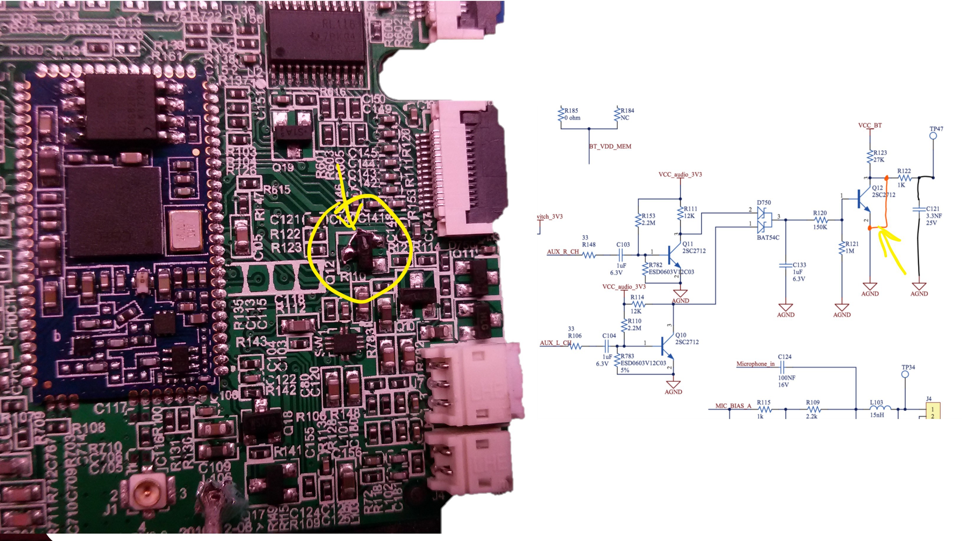
· A li-ion charger based on MP2637. Also can work as 5V boost converter, but this functionality is unused. Standby power is provided by a 3.3V LDO straight from Li-ion, and main power for peripherals is connected through a mosfet, and a bunch of other stuff.
· An IO expander chip.
· A bunch of opamps, with unclear purpose. I suspect, they are used as signal level detectors, to control the amp power supply.
The service manual for Flip 3 is available here: https://elektrotanya.com/jbl_flip_3_sm.pdf/download.html
I know I know, it’s not Flip4. But, it has full schematics, they are reasonably similar, and will help you trace out the pcb should you want to.
Drivers
Who knows what they are... probably something custom by JBL. They look very beefy. (see photos in project gallery)
I have measured their motor performance (BxL), got 3.0 newtons of thrust per amp of current. DC resistance is 3.52 Ω, so it’s 1.6 N rms thrust at 1 W input power. It’s an incredibly powerful motor for this small a speaker, which is obviously there to push some bass from a small enclosure. From this value, I can suggest a replacement driver – a very comparable one can be extracted from Blitzwolf BW-3 bluetooth speaker... If you can buy one – they appear to be obsolete, and no longer available.
Passive radiators
They are tuned to 65-71 Hz (the value I get depends on amplitude, not sure why).
DSP
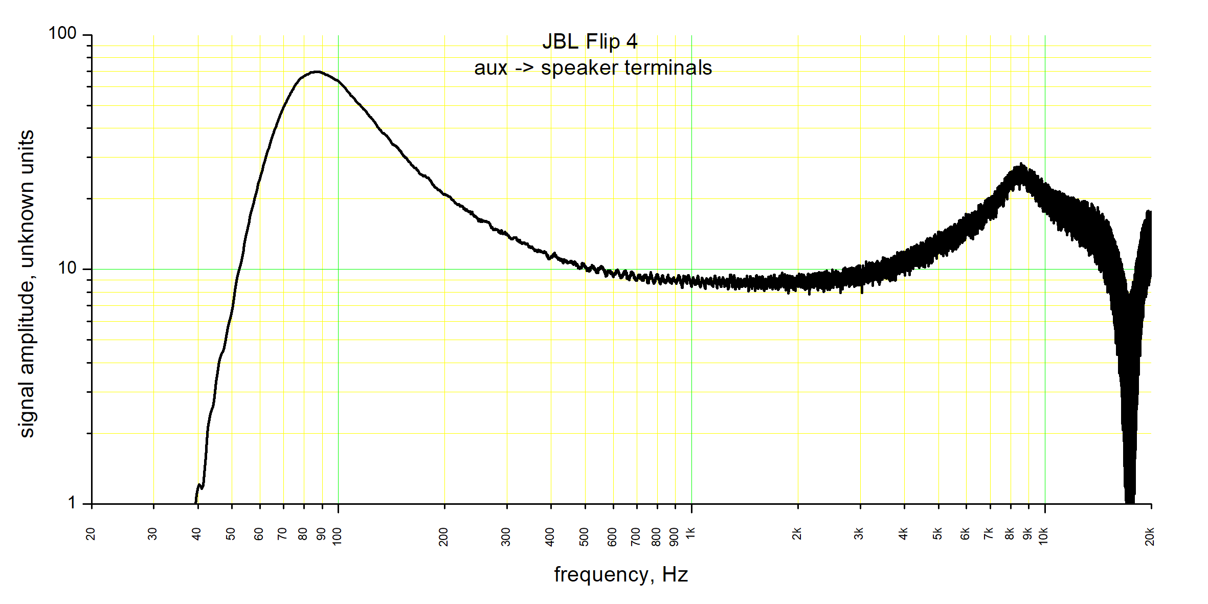
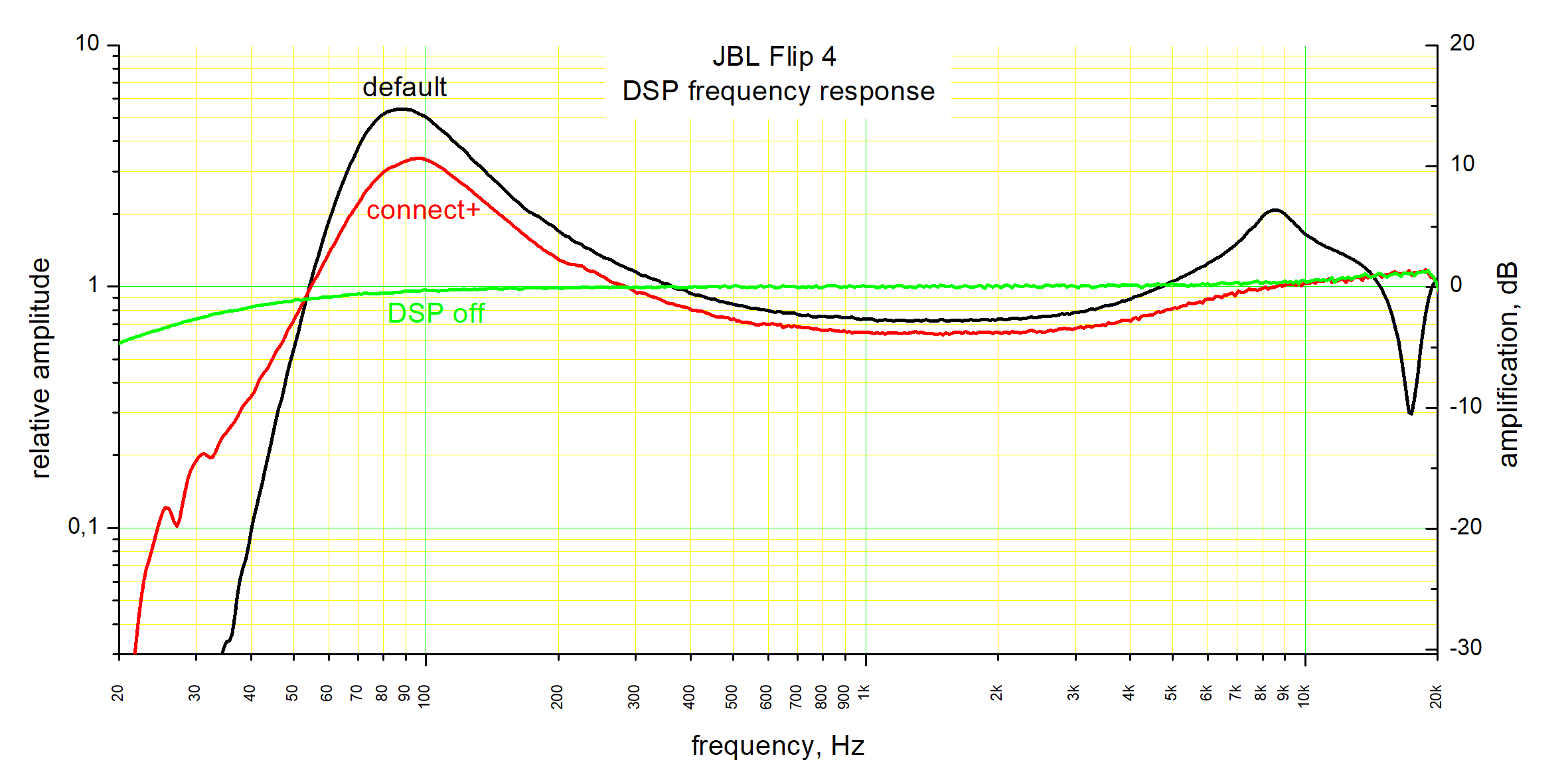
The input-to-amplifier-output frequency response of this speaker is not flat. That is how they achieve that impressive bass – there is built-in...
Read more » DeepSOIC


is possible way to change JBL FLIP 4 batter status LED color from white to purple ?