-
[Component Choices] All things i2c
06/29/2020 at 13:02 • 0 commentsi2c - along with SPI - are two protocols that allow communication between controllers. I2c (inter-integrated-circuit; it’s pronounced I-squared-C I believe) is a simple to use protocol allowing two way communication between a master device and multiple minion devices. These devices can be any sort of circuits - sensors, actuators, even other Arduino’s - and each can receive data from or send data to the master device. All this is achieved with just two wires; a data line and a clock line.
I won’t go in to much more detail here, but check out Sparkfun’s great guide to i2c for more info.
As already mentioned in the project log on the displays chosen for this project, I had chosen to use Adafruit’s 14-segment alphanumeric backpacks which communicated with the micro-controller using i2c. As such I was already setting up an i2c bus and so it was easy to integrate some more devices in to STJORN.
Proximity Sensor
One of the main reasons I went for the Line 6 enclosure is that it had a built in expression pedal, meaning I didn’t have to drag along a separate unit when I wanted volume or Wah control. I had, perhaps naively, assumed this was controlled with a potentiometer of some sort, but on opening the Line 6 controller up I discovered it actually used an IR based proximity sensor. Initially I tried to work out if I could somehow rig the pedal up mechanically to a potentiometer but after realising that could end up quite complex, I started to look for a way of using a sensor instead. My first though - coming from an automotive engineering background - was possibly a Hall effect sensor with a magnet mounted to the proximity ‘arm’ on the back of the expression pedal. This would undoubtedly have worked, but my searching lead to a better solution - Adafruit make an IR based proximity sensor board which would essentially replicate what the pedal was already designed for.![]() This board incorporates the IR LED, the receiver, plus all the associated electronics to send the data from the receiver over i2c to the micro-controller. Along with the library that goes with it, this means that in the program it is simply a case of requesting the current proximity and you get a nice, unitless, value back to work with. Easy peasy.
This board incorporates the IR LED, the receiver, plus all the associated electronics to send the data from the receiver over i2c to the micro-controller. Along with the library that goes with it, this means that in the program it is simply a case of requesting the current proximity and you get a nice, unitless, value back to work with. Easy peasy.Rotary encoder
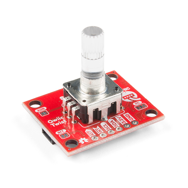
This was a very last minute addition when, on removing the PCB standoffs from the Line 6 enclosure, I inadvertently made an ‘additional ‘ hole in the enclosure,... The hole was fortuitously located and so I decided to fill it with a rotary encoder. I had previously thought about having some sort of menu system and with the addition of the encoder this would be possible.The encoder I chose was the Sparkfun Qwiic Twist. This little board mounts an ‘endless’ rotary encoder which incorporates a push button (by pushing down on the encoder knob) and also an RGB LED so that, along with a clear knob, the encoder can also be used to display information in colour.![]() All of this connects over i2c and the associated library spits out how many ‘ticks’ the encoder has moved so that readings can be made easily, and allows very simple control over the RGB colour.The ‘Qwiic’ part of the name of this board refers to a connector system Sparkfun use - it is a very small, push fit connector - you can just see on the right of the board above - that can be used to link multiple boards by carrying the data, clock, ground, and power between them. The board also incorporates normal solder points for these signals, but the connectors make it very easy to use, especially for prototyping.
All of this connects over i2c and the associated library spits out how many ‘ticks’ the encoder has moved so that readings can be made easily, and allows very simple control over the RGB colour.The ‘Qwiic’ part of the name of this board refers to a connector system Sparkfun use - it is a very small, push fit connector - you can just see on the right of the board above - that can be used to link multiple boards by carrying the data, clock, ground, and power between them. The board also incorporates normal solder points for these signals, but the connectors make it very easy to use, especially for prototyping.I2C Differential Breakout
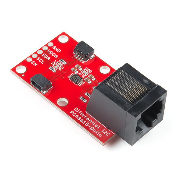
This, again, was a last minute addition and came about by accident whilst browsing through Sparkfun’s ‘Qwiic’ catalog after choosing the encoder board above. Having an RJ45 shaped hole in the STJORN enclosure I had nothing to fill with the sight of an RJ45 connector sparked my interest. On closer investigation this little board would open up some great expansion possibilities.That board is Sparkfun’s i2c differential breakout and what it does is take the i2c data and clock signals and ‘convert’ them to differential signals that can be sent over CAT5/6 cable. Standard i2c has a very short maximum distance it can send and receive data as it is designed for commas between circuits within a particular unit. By converting to a differential signal and sending over Cat5 to another of these circuits in another device allows two devices to communicate with i2c but at distances of hundreds of feet from each other.![]()
Although this wouldn’t immediately add anything to the STJORN controller, I have some uses for it which could really expand the possibilities of this controller:
- ‘Remote’ control - Where I will be using STJORN most, it is often useful for another member of the band to be able to have control over clicks and tracks. By using this device to link to another, simpler, foot controller, this ‘remote’ can send signals to STJORN via i2c and be able to control in the same way STJORN does. As the communication is bi-directional it also means statuses can be sent back the other way. This is a really exciting possibility for my use case and will be the next thing to be developed!
- FX Switcher - another possible use is to hook STJORN in to a remote FX switching system. The receiving device would be a set of relays allowing switching in and out of analog FX units in to the signal path going to the audio interface. As the range of the i2c comes using this board is long, the FX switching board could be located close to the interface rather than having to take up floor space on stage.
- MIDI converter - a very simple one, but this port could be used to add MIDI I/O to STJORN. This is already present in some way on the audio interface I use, but by incorporating it in to the STJORN controller means that external MIDI can be processed by STJORN before it is sent on to my laptop (or wherever). A device such as this could also be used to turn any MIDI capable controller in to a ‘remote’ as described above.
Nothing firm for the use of this yet and, at minimum, it just fills a hole in the enclosure - but hopefully interesting things to come!
-
[Component Choices] Light-up Bits
06/29/2020 at 12:19 • 0 commentsAdafruit’s ‘Neopixel’Along with plenty of footswitches to control a modelling rig, a good foot controller also needs some appropriate light-up bits to give the user feedback on what’s happening.
For STJORN, feedback from the software is displayed in two ways - RGB LEDs and Alphanumeric displays.
RGB LEDs
The most basic way of signalling feedback is with a simple LED to show an on/off status. A more interesting form is using an RGB LED to not only be able to show status with on/off but also by colour, and this is the route I decided to take for STJORN.The simplest form of an RGB LED is the four lead variant - these have either a common anode or cathode, and then 3 of the opposite; one for each colour; effectively three LEDs in a single case. By activating each LED you can obtain a mix of red, green, and blue. Simple to achieve but has some downsides - this form is only capable of producing 7 colours (red, blue, green, cyan, yellow, magenta, and white) without having to resort to using variable resistors or PWM, and also requires three output pins on the micro-controller for each LED.![]() (Image from a good article on how RGB LEDs work, here)STJORN was to have 14 LEDs so using the four-lead type of LED would have required 42 pins...The answer is to use addressable RGB LEDs. These are essentially a four-lead RGB LED along with a WS2812 controller. A commonly used version of these is Adafruit’s ‘Neopixel’ range which comes in a variety of forms. The version I am using is a generic 5mm through hole version but does exactly the same.What the WS2812 does which makes this type of RGB LED so easy is two-fold:
(Image from a good article on how RGB LEDs work, here)STJORN was to have 14 LEDs so using the four-lead type of LED would have required 42 pins...The answer is to use addressable RGB LEDs. These are essentially a four-lead RGB LED along with a WS2812 controller. A commonly used version of these is Adafruit’s ‘Neopixel’ range which comes in a variety of forms. The version I am using is a generic 5mm through hole version but does exactly the same.What the WS2812 does which makes this type of RGB LED so easy is two-fold:- The controller handles colour mixing and so hundreds of different colours are possible
- Each individual LED is addressed and controlled by a single wire bus - this means hundreds of LEDs can be controller using a single pin on the micro controller!
Although this form is slightly more expensive than a basic four-lead version, the advantages are huge when using more than a couple of LEDs and worth every penny!
Alphanumeric Displays
LEDs are great for showing a status of some particular feature, but for more detailed feedback an alphanumeric display of some form is usually required. There are many choices - LCD, OLED, multi-segement LED, LED matrix, etc - but what I settled on for STJORN was to use 14-segment LED alphanumeric screens.The reason I chose this form is that although the text display may be rudimentary compared to LCD or OLED, this can actually be a bonus as the text is big and clear. The STJORN controller doesn’t really need to show a huge amount of text, but clarity is key and so this form won.In a similar way to RGB LEDs, the ‘simplest’ form of multi-segment display is where each segment is treated like an individual LED. Each LED is assigned it’s own pin on the micro-controller and by turning each segment on and off you get your letters and numbers. However, here we have an even bigger problem than the RGB LEDs - the STJORN display is to have 12 characters, each with 14 segments in, and so requiring a grand total of 168 pins on the micro controller! This can be made less using matrixing etc, but there is a much simpler way...As RGB LEDs are available with a controller, so are multi-segment displays. The ones I am using are Adafruit’s 14-segment backpacks - these are a small circuit board which attaches directly to the display ‘segments’ and allows the display to be controlled using the i2c protocol.![]() Each display ‘block’ is two characters and each backpack controls two blocks, therefore STJORN required three backpacks. The i2c protocol is a two-wire system and like the RGB LEDs, each display is addressed so multiple displays can be used with the same i2c bus and only needs two pins total on the micro-controller! The other benefit is that using the Adafruit’s library for these displays they can be controlled as simply as telling each character to display an ASCII character rather than having to control each individual segment (although this can be done as well if required).By using both these forms, I was able to design STJORN with 14 RGB LEDs and 12 characters worth of alphanumeric display all whilst only taking up 3 pins on the Teensy controller and making them very easy to control.
Each display ‘block’ is two characters and each backpack controls two blocks, therefore STJORN required three backpacks. The i2c protocol is a two-wire system and like the RGB LEDs, each display is addressed so multiple displays can be used with the same i2c bus and only needs two pins total on the micro-controller! The other benefit is that using the Adafruit’s library for these displays they can be controlled as simply as telling each character to display an ASCII character rather than having to control each individual segment (although this can be done as well if required).By using both these forms, I was able to design STJORN with 14 RGB LEDs and 12 characters worth of alphanumeric display all whilst only taking up 3 pins on the Teensy controller and making them very easy to control. -
[Build Log] Chassis Finishing and Graphics
06/06/2020 at 11:49 • 0 commentsOnce the chassis modifications were complete, it was time to re-finish the chassis and apply some graphics to turn the old Line 6 controller in to Stjorn!
The chassis itself had no rust or other superficial issues and so preparation for re-finishing was pretty straight forward. An overall light sand with some 180 grit to provide a key for the undercoat and then cleaning with some white spirit to get rid of any grease or grime it had accumulated and it was ready for painting.
The paint I used was in rattle-can form and all sourced from Riolett Custom Aerosols in the UK (https://www.riolettcustomaerosols.co.uk/). The paints I used were:
- 1K Grey Primer
- 1K Acrylic Full Gloss top coat in BS 381C RAF Blue/Grey 633
- Fun fact: this is the blue/grey colour Neve use for their consoles - and is why I chose it!
- 1k Clear Lacquer
The '1K' refers to the hardness of the paint once dry - 1K and 2K are available but 2K is a bit overkill for this sort of project so I went with the 'standard' 1K.
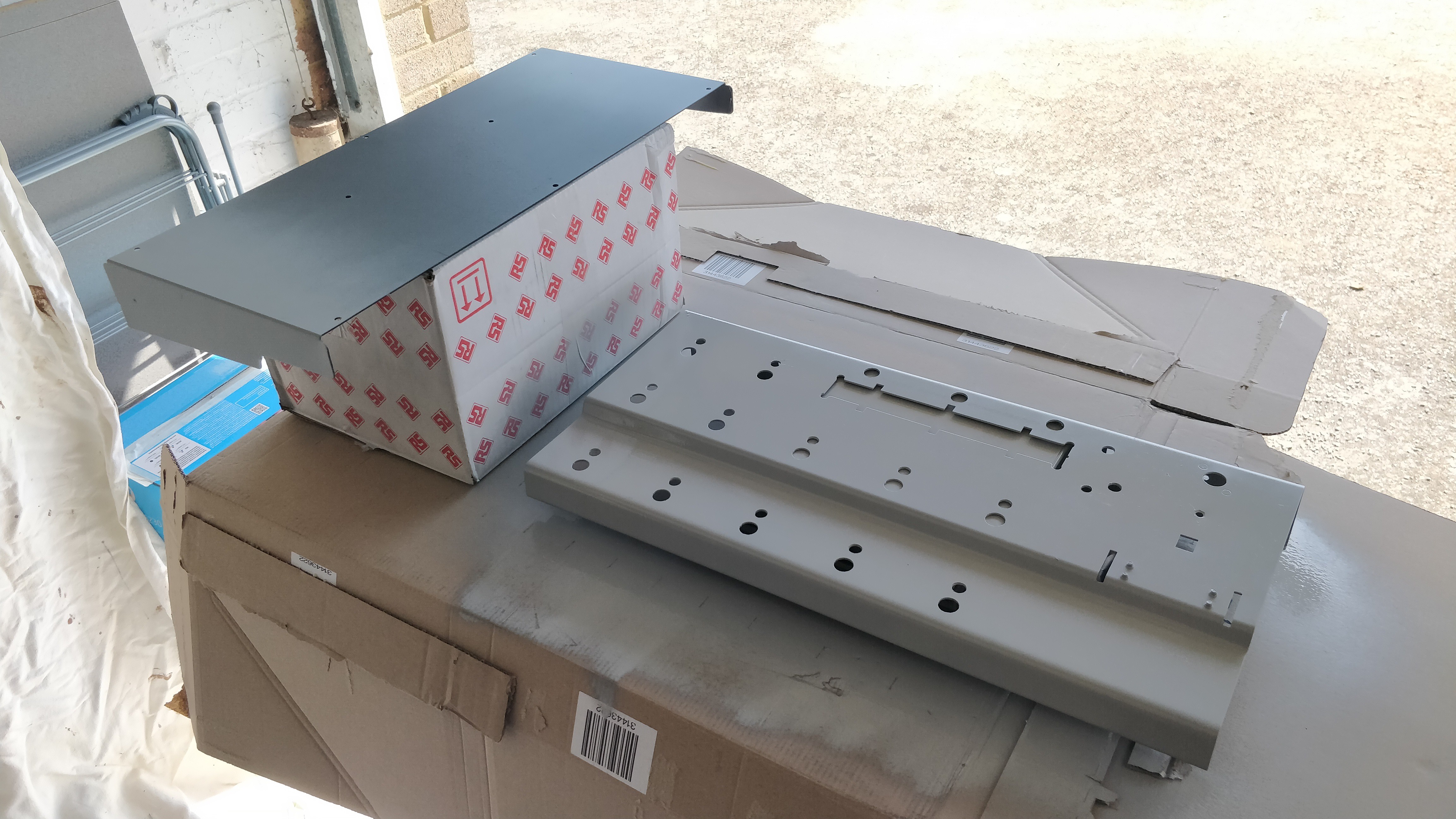
The primer went on beautifully, producing a very smooth coat.
![]()
(at first for some strange reason I wasn't going to paint the whole of the bottom..... I went back and resprayed that part though!)
The first layer was allowed to dry fully for 24hours, lightly sanded with some 600grit sandpaper, and then a second coat applied. With the second coat dry and lightly sanded again it was time for the top coat.
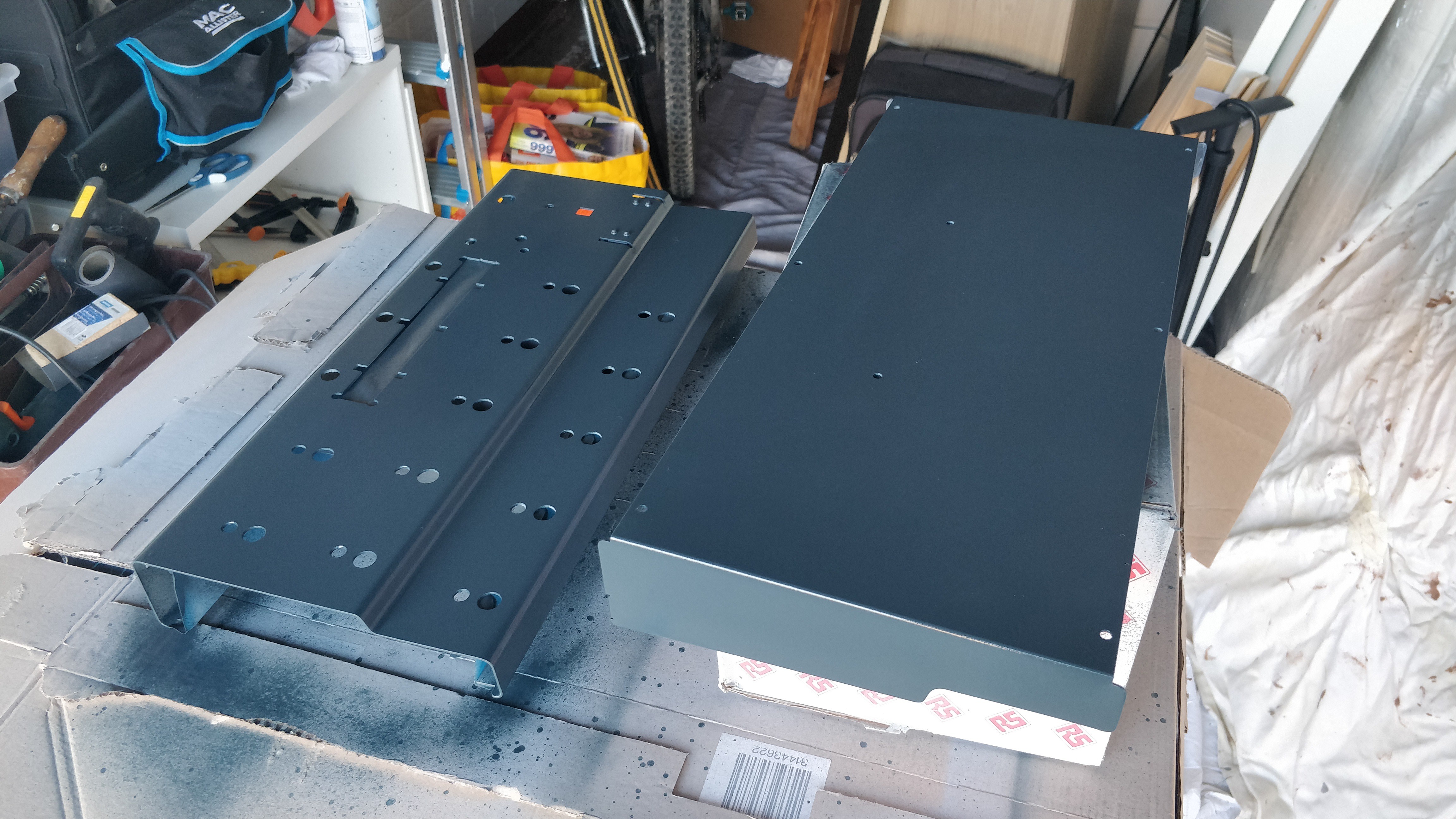
Again this went on very easily and once it was dry it actually didn't need a second coat at all as the coverage was very good.
![]()
Looking good in it's Neve grey/blue it was time to think about graphics...
I wanted the unit to have some good, high quality graphics on it and not just use some PVC tape and marker pen or some dodgy paper stickers - essentially I wanted it to look as much like a production device as possible.
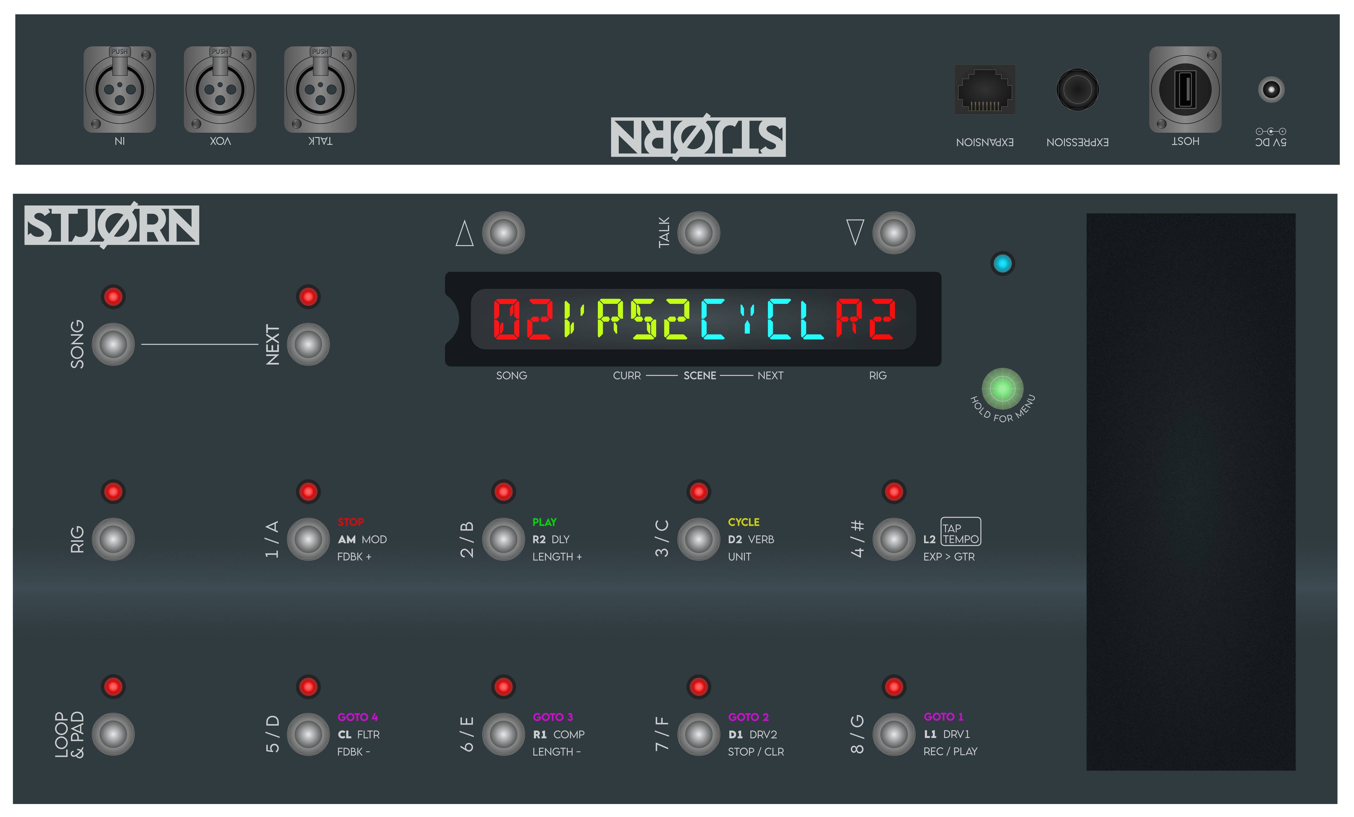
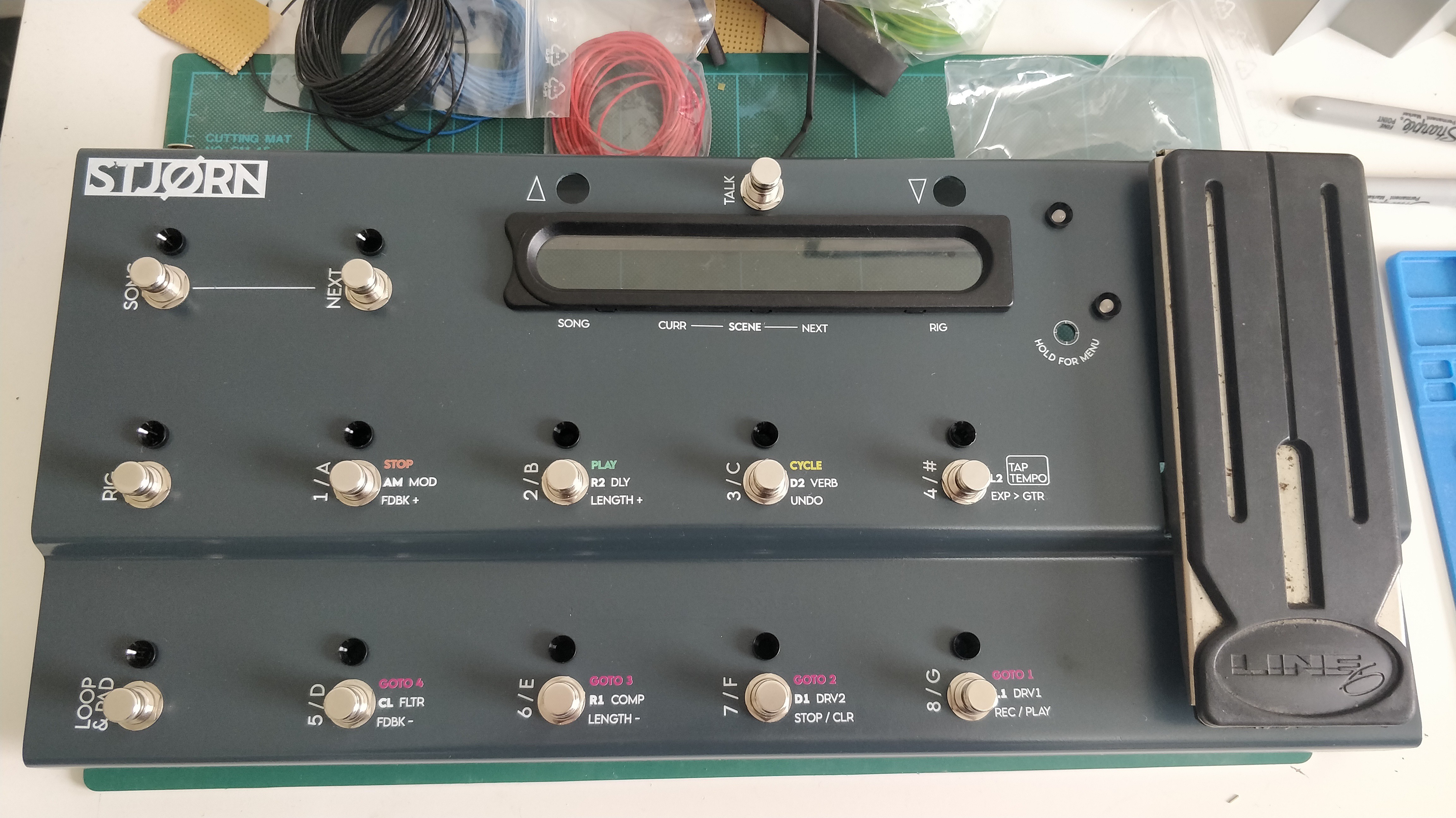
I fired up Affinity Designer and set to work trying to come up with a design. I'm not a graphic designer by any stretch but generally have a reasonably good idea for 'clean' design and - after taking cues from other controllers out there like the Line 6 Helix, Kemper, etc - think I have come up with graphics that are useful enough to show what everything does without cluttering the controller.
![]()
For each of the 8 main buttons, the text on each 'row' is applicable to the 3 modes - SONG, RIG, and LOOP & PAD - that are selected using the 3 buttons on the left. On the second row of text the text in bold - e.g. AM, R2, D2, etc - determines the patch that is selected in one of the RIG modes, and then the other text next to it is the FX selected in the other RIG mode. In another post I will go in to more details on the control scheme.
I like the primary use of White for most of the labels with just a small amount of colour used for the SONG transport controls.
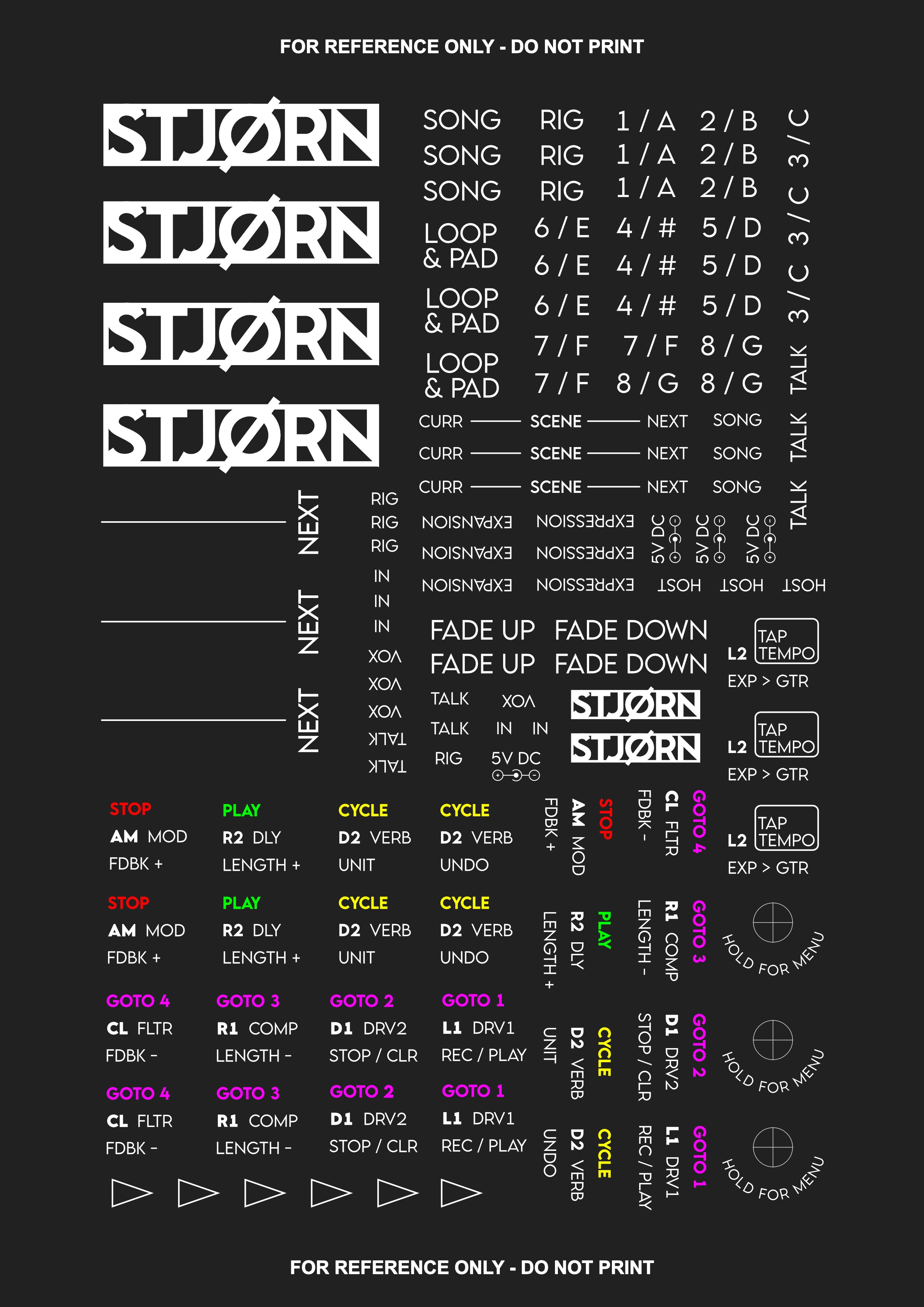
As the text is mostly white with no background, I needed to find a way to replicate that in a medium I could apply myself to the unit.
The answer came from a company who mostly make waterslide decals for minature railway modellers - Precision Decals. They are able to print completely custom decals and, most importantly, have the ability to print in white; something that is not possible using a home inkjet printer and transfer paper.
The graphics were prepared according to the instructions they provide and sent off. I included multiple repeats of each graphic so that when I inevitably screwed up placing one I had a few attempts!
![]()
When the graphics came back they already looked superb on the paper and I couldn't wait to apply them to the unit.
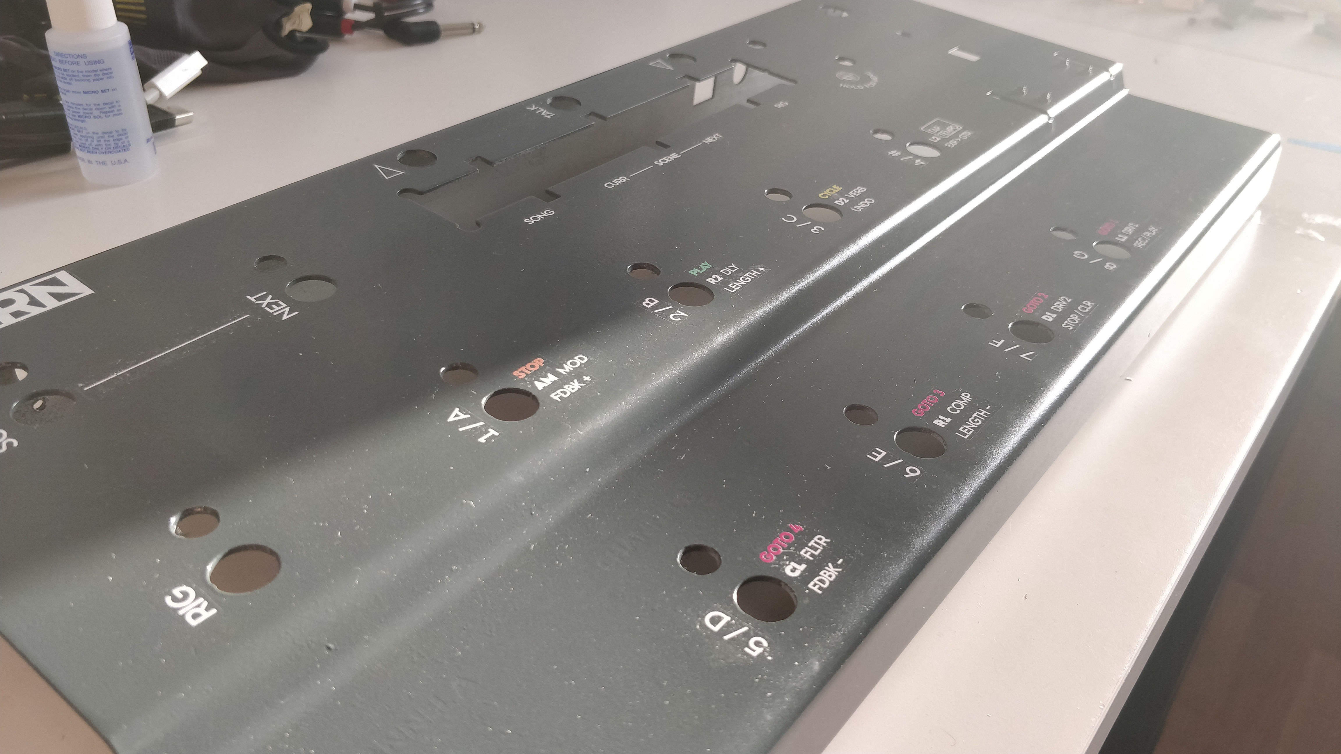
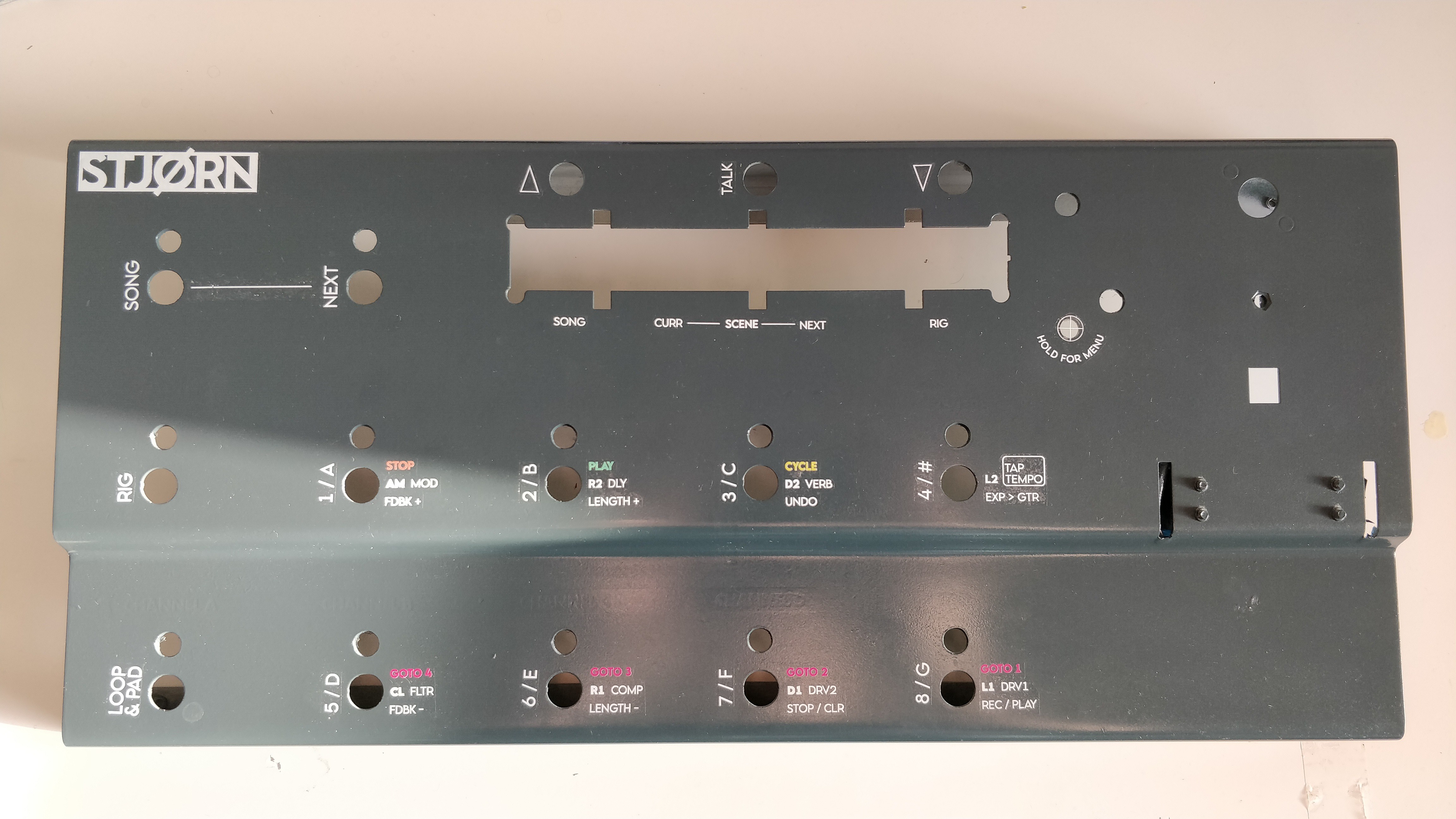
For those who haven't used waterslide transfers before they are applied by soaking the graphic in water for a minute or so and then sliding the decal from the backing paper in to position. Generally normal tap water can be used but I also purchased some Microscale Microset to help. This solution is applied to the surface the decal will be laid on and then also brushed over the decal once it is in position, and it helps to soften the decal to conform to any irregularities in the surface and also provide better adhesion to the surface. The whole process is a bit of a faff, but a Sunday afternoon later it was done!
![]()
![]()
In the photos above, you can see some 'silvering' of the decals - this is where tiny air bubbles are trapped behind the clear part of the decal. The Microset helps get rid of this, but clearly the surface wasn't as smooth as it could be and so trapped some air bubbles. It is most noticeable on the line between SONG and NEXT on the top left - this took three attempts to lay the decal and required a large width of clear backing to be left so that the decal didn't break. I used some Microset and a craft knife to try and scrape away as much as possible, but there was still some left annoyingly.
Final step was to let the decals set properly for 24 hours and then apply the clear lacquer. This was applied in two thin coats with 24 hours in between for each coat to dry. When I went down to the garage after the second coat had dried I was very very pleased to see that the lacquer appeared to have dissolved pretty much all of the clear parts of the decals, just leaving the text behind! This was most noticeable on the HOLD FOR MENU graphic - the circle with cross you can see above that was used to position the decal over the hole had all the backing dissolved away just leaving a very thin cross covering the hole. The main upshot of this though was that all the silvering - especially on the line mentioned above - had gone!
The end result, I think, looks superb and I am really REALLY happy with it!
Here it is with pretty much all the hardware in place and looking great!
![]()
(The Line 6 on the expression treadle will be changing by the way!)
-
[Electronics] Mic Switcher
05/22/2020 at 06:37 • 1 commentThe main 'scene' that I play in is at church where we will almost always use IEMs for monitoring. In order to be able to communicate with the band I need a talkback microphone - a mic that is routed to all the musicians IEMs but not Front of House so that I can talk to them without the congregation hearing.
We have been making great use over the last few years of a Radial Hotshot mic switcher - this allows a single microphone to be used for both vocals and talkback.
![]()
The output of the mic goes in to the hotshot which then has two outputs - one to the vocal channel of the mixing desk, the other to the talkback channel. When the button is not pressed the Hotshot routes the microphone to the vocal channel and when it is pressed it goes to the talkback channel. Simple and really useful.
Part of creating the STJORN controller (and system around it) is to try and remove as many complications when actually playing as possible. One way is to cut down on the number of different footswitch devices at my feet - currently three; a controller for my guitar rig, one for tracks, and the hotshot.
As such, the idea came to include a mic switcher within the STJORN footcontroller - that way I would have all three pedals in a single unit.
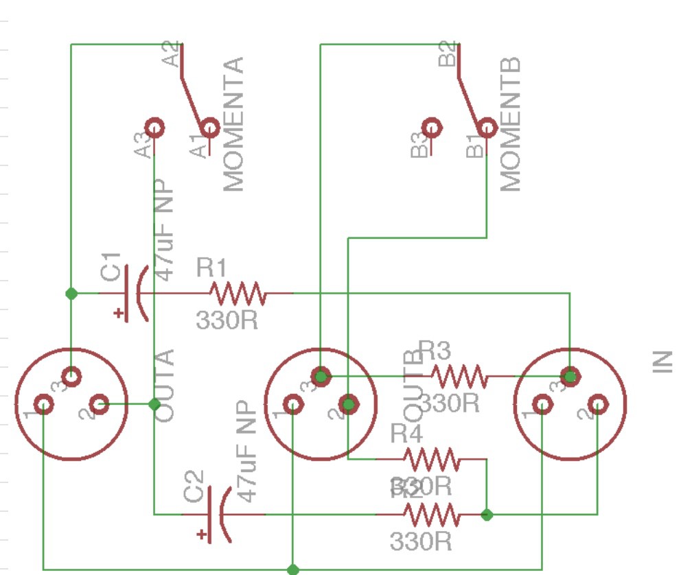
It took a little bit of searching, but I eventually found a circuit diagram for a mic switcher that had some good comments that it worked well. That circuit is thusly:
![]()
It's a pretty simple circuit. A DPDT switch is used for the switching and the circuit works by shorting out the two hot signals of the 'unused' mic channel. NOTE: The capacitors are NOT polarised as is shown - I can't find where I got the diagram from, but the comment was that when the creator made the diagram he couldn't get it to add non-polarised symbol. I've made this with non-polarised caps and it works!
In the hotshot the switch is a mechanical footswitch and initially this is what I was going to use. But then the thought came that I could use a footswitch through the Teensy to control the mic switcher via a relay. This then opens up some interesting control possibilities such as using a double tap to latch the relay if I need to talk for extended periods, indicating the status of the switch using one of the NeoPixels, controlling the switch via MIDI, etc.
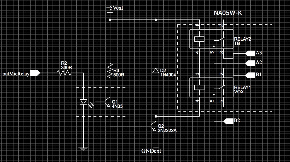
A bit of reading up on the design of relay circuits and the following was designed:
![]()
To start with, I wanted to ensure that the audio was kept as noise-free as possible. As such, the circuit design is fully isolated from the rest of the electronics within the STJORN controller. The first part of the isolation is that the signal from the Teensy to control the circuit goes through an opto-isolator. The second is that the +5Vext and GNDext which power the relay are from a 5V-5V DC-DC converter. This provides an isolated 5V and GND just for the relay circuit. Thirdly is, of course, the relay itself which separates the audio circuit from the others. This is most likely overkill but for the sake of a few extra components it was easy to design in and should help keep the signal nice and clean.
The circuit itself is pretty simple:
- The signal from the Teensy comes in to the 4N35 opto-isolator via a resistor - the resistor is required as the opto-isolator has an LED inside so, as always, a resistor is required to limit the current
- Note: the schematic shows a 330R on the input to the 4N35, I actually used a 470R in the end; either is fine; just run the calcs using V=IR
- An opto-isolator works by using the input signal to light an LED within the opto-isolator IC
- On the 'other side' of the IC is a photo-transistor which reacts to the light from the LED.
- When light is present, the photo-transistor base allows current to flow from the collector to the emitter and current flows around the circuit.
- When the light turns off no current is allowed to flow and the circuit is turned off.
- As there is a literal air-gap between the LED and the photo-transistor, this component allows complete physical isolation between circuits.
- The 500R resistor on the input to the photo-transistor is there to limit current; again, I actually used a 470R here
- For the relay circuit itself, the emitter of the opto-isolator is connected to the base of an NPN transistor
- When the opto-isolator is active, the current in the circuit opens the base of the NPN transistor and allows current to flow from +5Vext to GNDext
- The presence of the 1N4004 diode means that the current from +5Vext to GNDext flows through the relay
- Thus, when the opto-isolator is active, current flows through the relay and energises the coil - when the opto-isolator is off the relay opens
- The 1N4004 diode is there to protect the circuit against 'flyback' voltage when the relay opens
- This can cause very high voltages in the circuit and the diode creates a loop circuit to protect against this
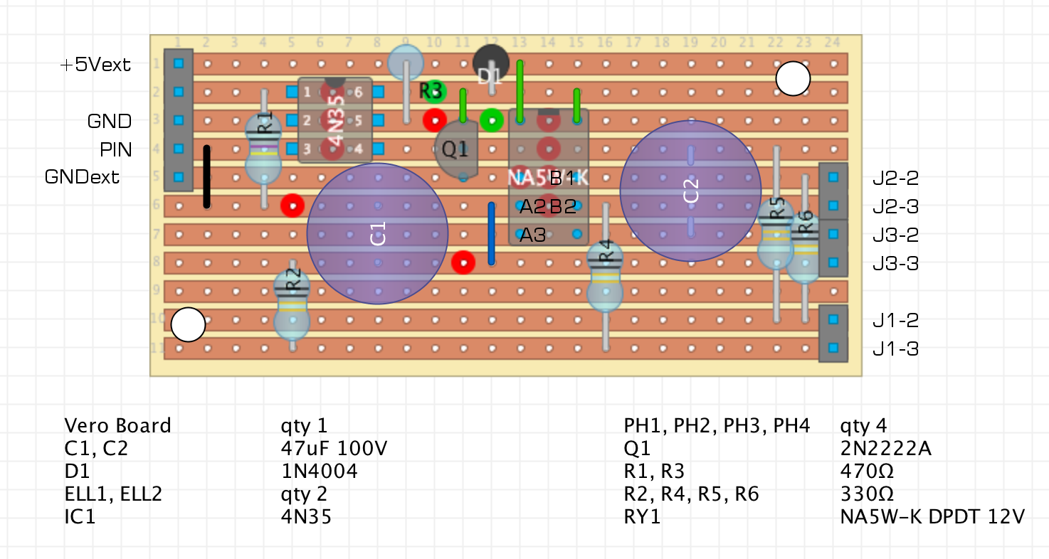
With the two circuits designed, it was time to put them together in a stripboard layout. I used the excellent DIY Layout Creator to do this :
![]()
A note on the design - it all was nice and clean until I soldered it up and realised I had the +ve and -ve of the relay the wrong way round.... This lead to the modifications shown in green at the top of the board to reverse this; fortunately a relatively straight-forward task. The takeaway from this is ALWAYS READ THE SPEC SHEET PROPERLY!
The 4N35, 2N222, and relay are all socketed so that I didn't damage them when soldering. The rest is hard-soldered to the board.
As part of trying to work out why it wasn't initally working (due to the relay being inverted...) I also added an LED to the relay circuit. This is driven by the transistor in the same way the relay is so gives good indication if the circuit is working. The LED is socketed as I didn't need it in the circuit all the time but is useful for debugging. It fitted nicely in the space at the top left - I shall leave you to work out the mods needed to fit it in if you want to do the same :)
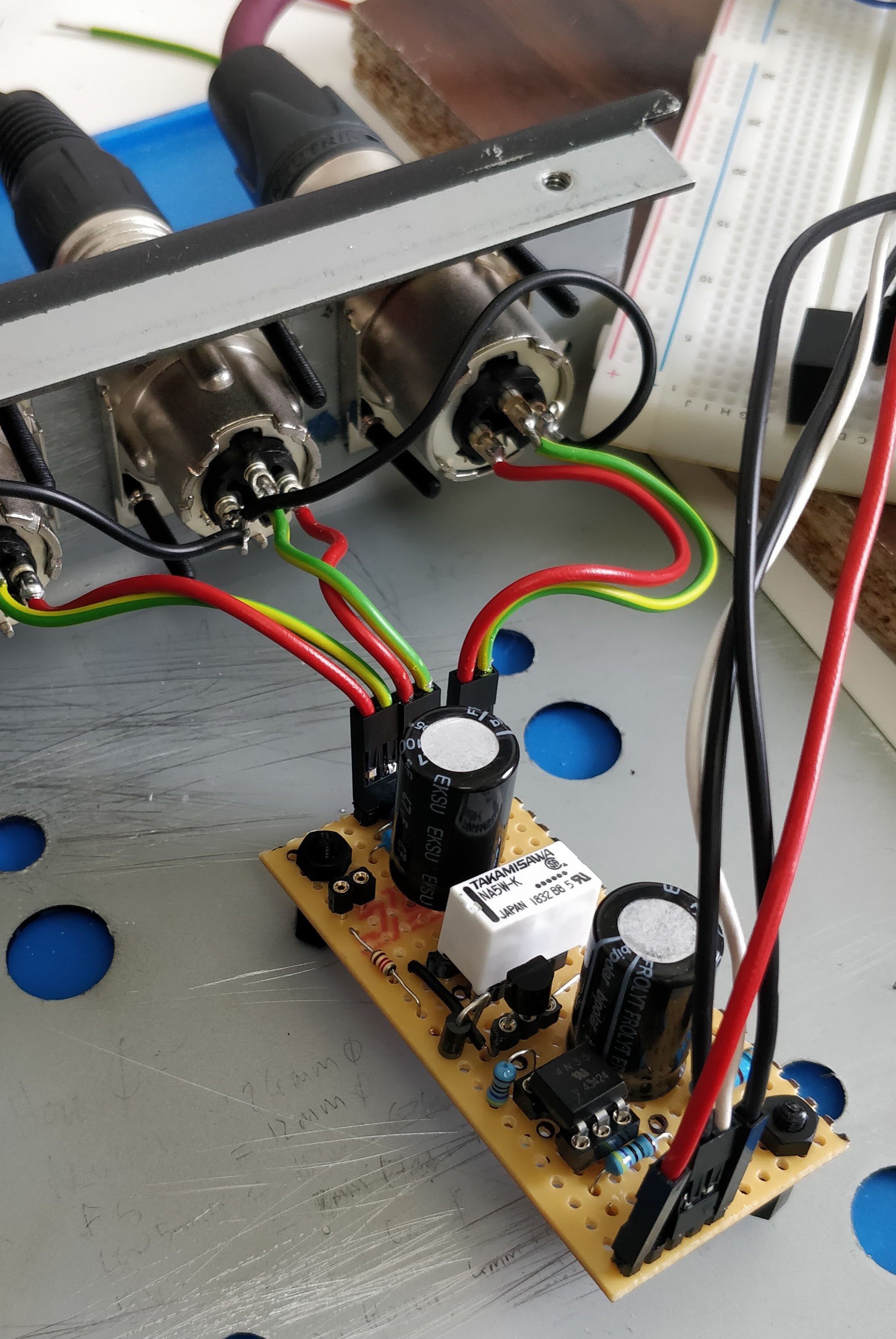
And here is the circuit all wired up to be tested:
![]()
Once the initial kerfuffle with the relay was sorted it worked brilliantly. I tested it by hooking it up to my interface and using a modification of the simple Arduino 'blink' code to turn the relay on and off every few seconds and it works really well. Nice and clean and quiet.
This should be a really useful addition to the controller once it is fully plumbed in and coded up and I am glad I decided to add it in.
Splendid.
- The signal from the Teensy comes in to the 4N35 opto-isolator via a resistor - the resistor is required as the opto-isolator has an LED inside so, as always, a resistor is required to limit the current
-
[Build Log] Chassis Modifications
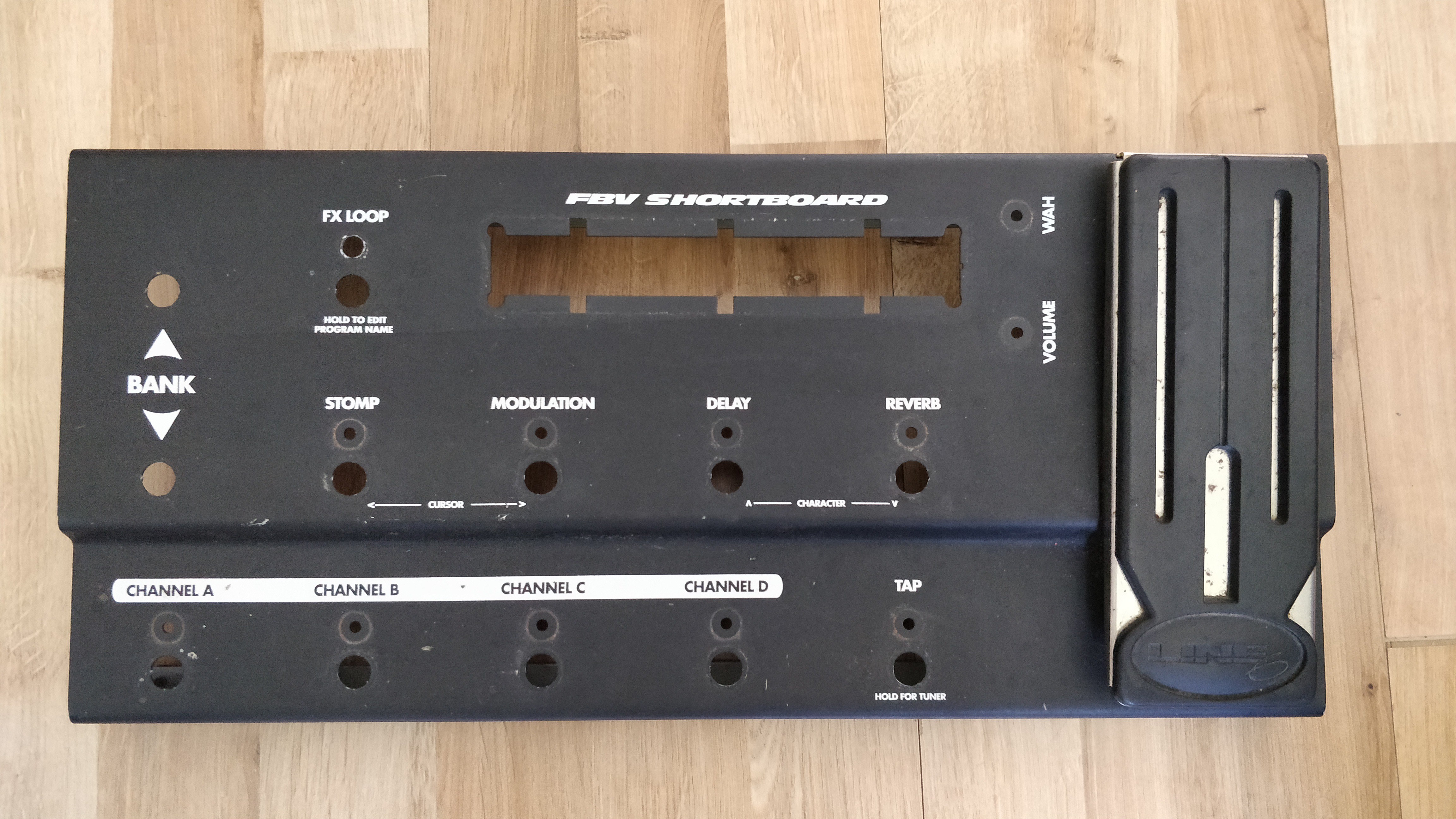
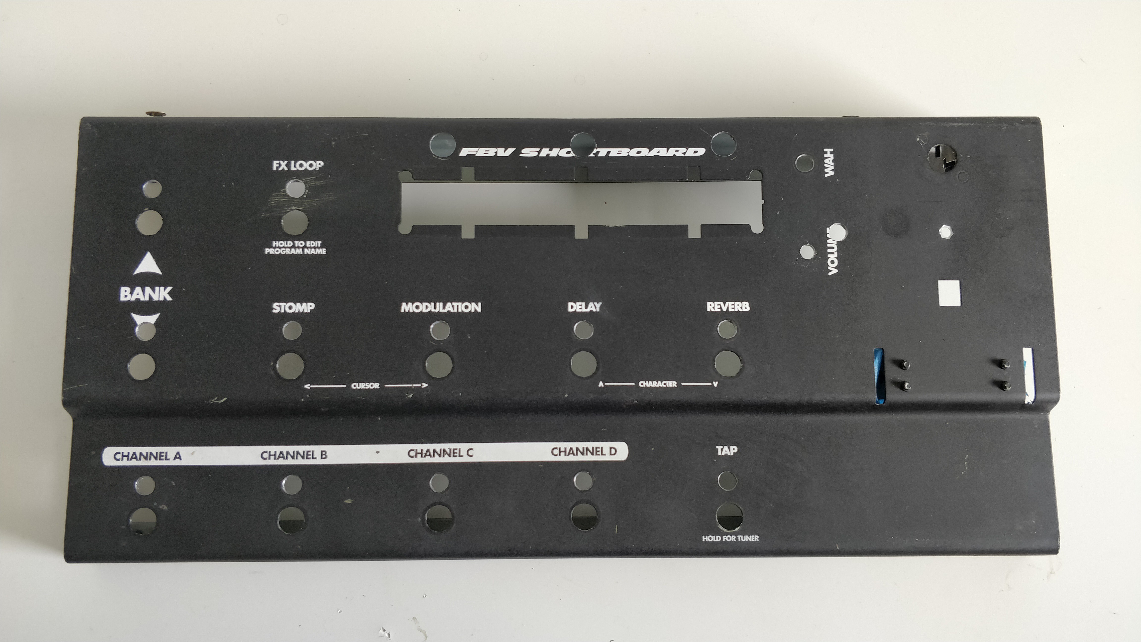
05/14/2020 at 12:08 • 0 commentsFirst task for the STJORN build was to rip the guts out of the Line 6 FBV Shortboard chassis. I wouldn't be re-using any of the internal components so out they all came. In hindsight I probably could have made use of the footswitches but prefer the 'non-clicking' ones I will be using.
![]()
![]()
(Internal view showing some initial sketch thoughts of where components might be placed)
Step 2 was then to modify the chassis to accomodate the additional switches and sockets that I would be adding.
From the base chassis, the modifications I needed to make were:
- Drill holes for the three additional footswitches above the display
- Drill holes for the additional LEDs (one above each footswitch)
- Widen the current LED holes to accomodate 5mm through hole LEDs in sockets
- Remove the PCB standoffs
- Punch out the holes on the rear of the chassis for the XLR and USB Neutrik D size connectors
- Drill a hole on the rear for the DC power connector
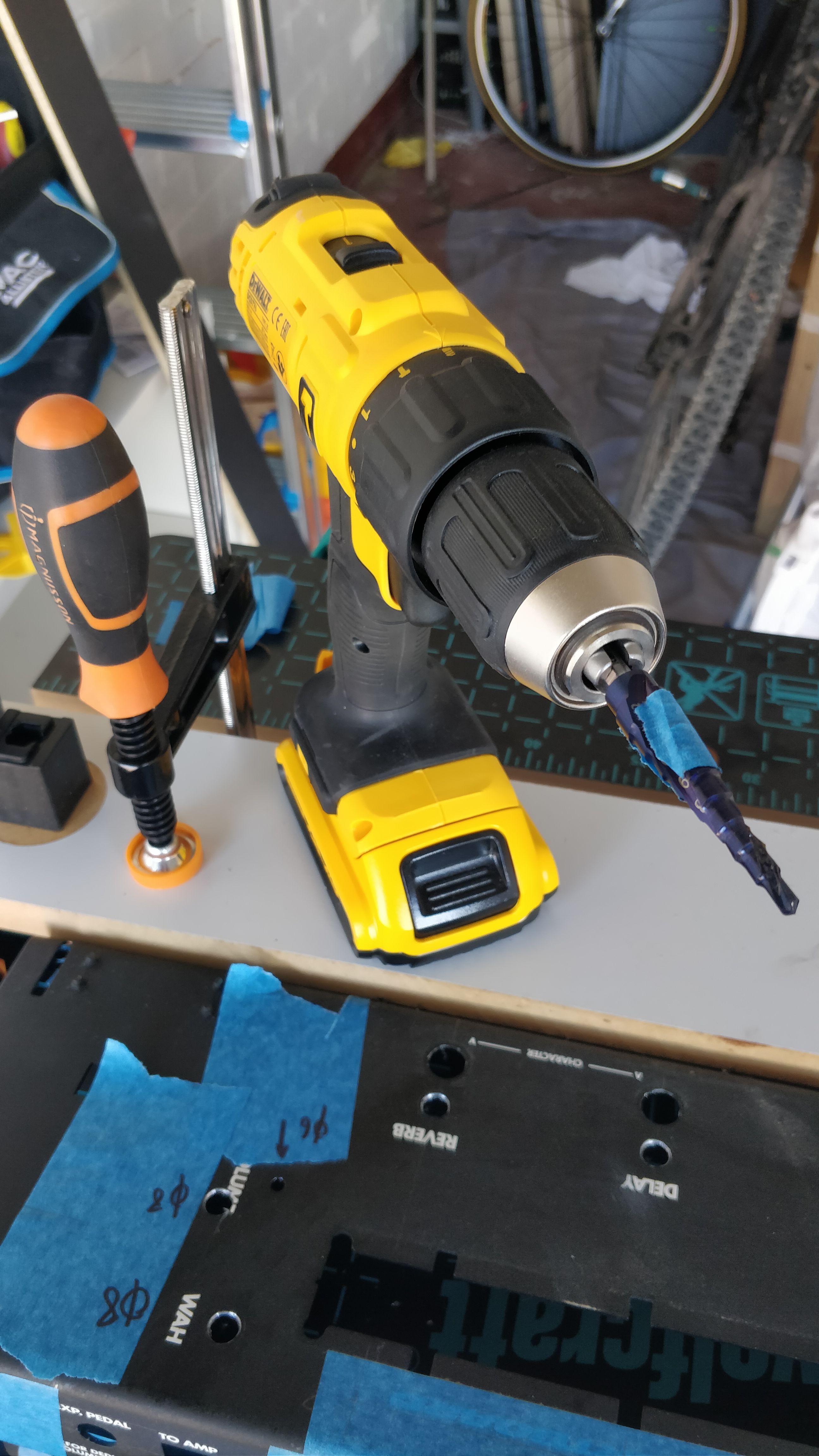
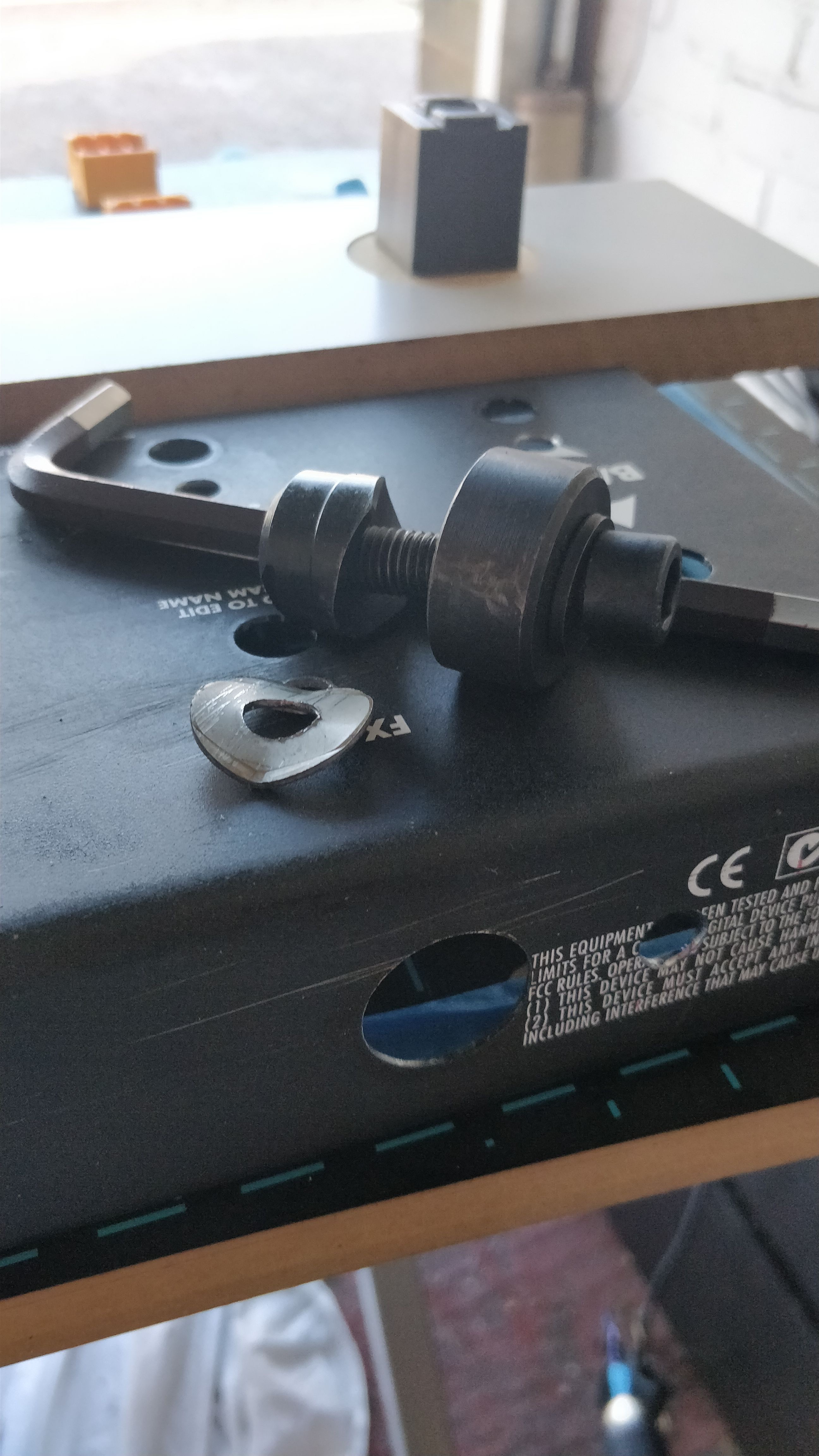
Not a particularly large or arduous list but made even easier by two purchases I am very glad I made - a step drill bit and a Q-Max knockout punch.
Even though I have made various FX pedals and other similar projects in the past I have never invested in a step drill and have just used successively large drill bits to drill footswitch holes etc. Step drills are just so much better! Within literal minutes of marking up and centre-punching I had drilled all of the new footswitch and LED holes (I did use a 3mm drill as a pilot first) and enlarged the existing LED holes.
![]()
A quick once over with a hand-reamer and all the holes were good to go.
Next up was drilling the holes on the rear for the various connectors. The main ones were four Neutrik D sized connectors for the mic-switcher XLR sockets, and the main USB socket. Neutrik D connectors require a 24mm diameter hole for the main chassis and then 2off 3mm holes for the mounting screws. Second best purchase so far made this very easy - the Q-max knock-out punch.
Using the Q-max is a piece of cake - you simply drill a 10mm hole and then push the threaded part of the punch through. You then attached the cutting half of the punch to the other end and just tighten it with an allen key. The punch easily munches through the chassis leaving a perfect 24mm hole.
![]()
Four-off 24mm holes created in about 5 minutes - simple!
The only annoyance of this whole procedure was when I removed the PCB standoffs. I had a thought that I could just wrench them off the inside of the chassis with brute-force and ignorance. Sadly the latter part of that phrase came in to play when I realised that doing so now left a hole in the top of the chassis...
However, I turned an annoyance in to something useful and drilled out the small hole to accomodate another LED - I had actually removed one of the LEDs from teh design when I decided to add a rotary encoder in it's place and fortunately the accidental hole was right next to where the encoder would sit and provides a good location to have another LED. So disaster averted.
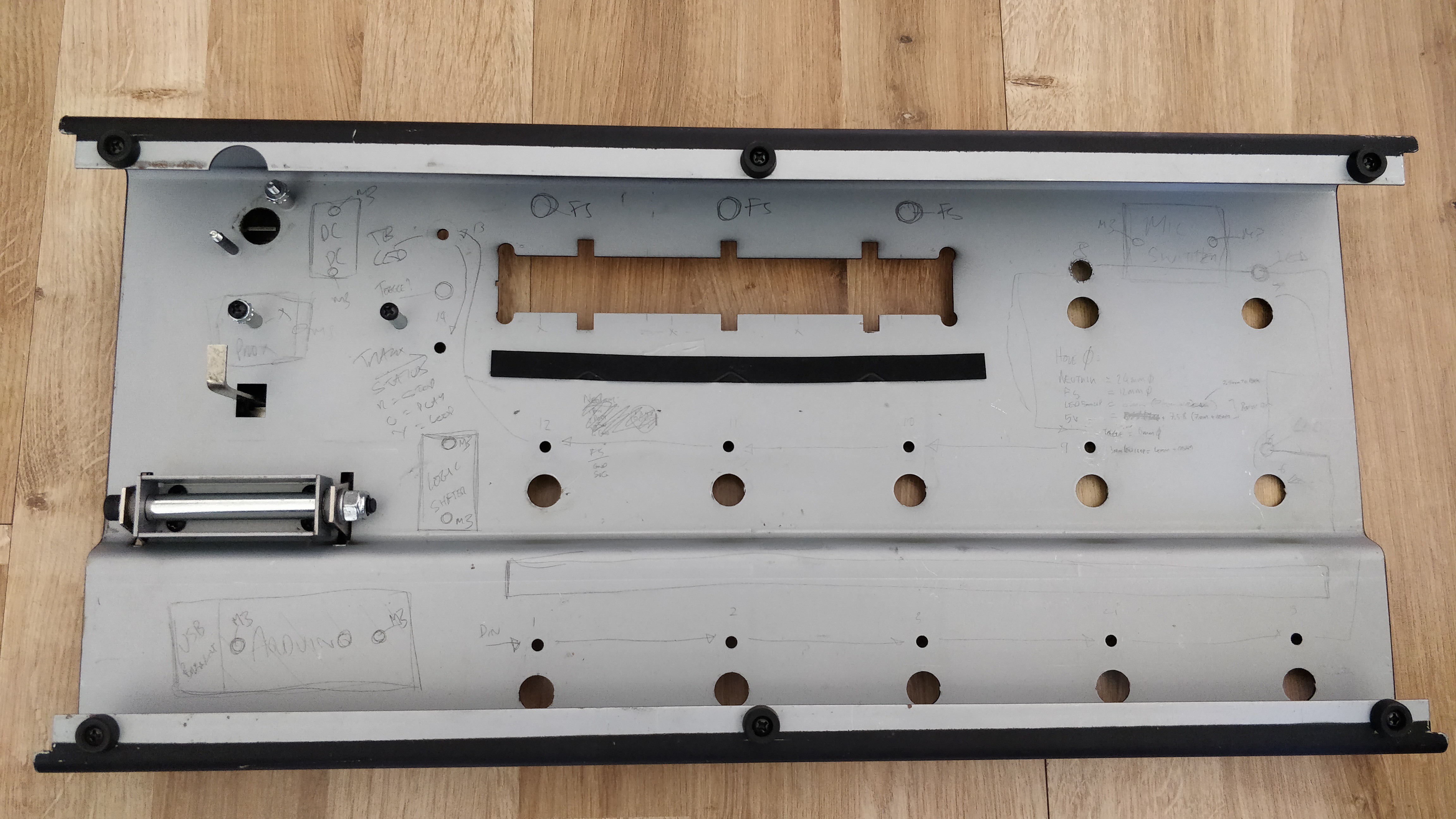
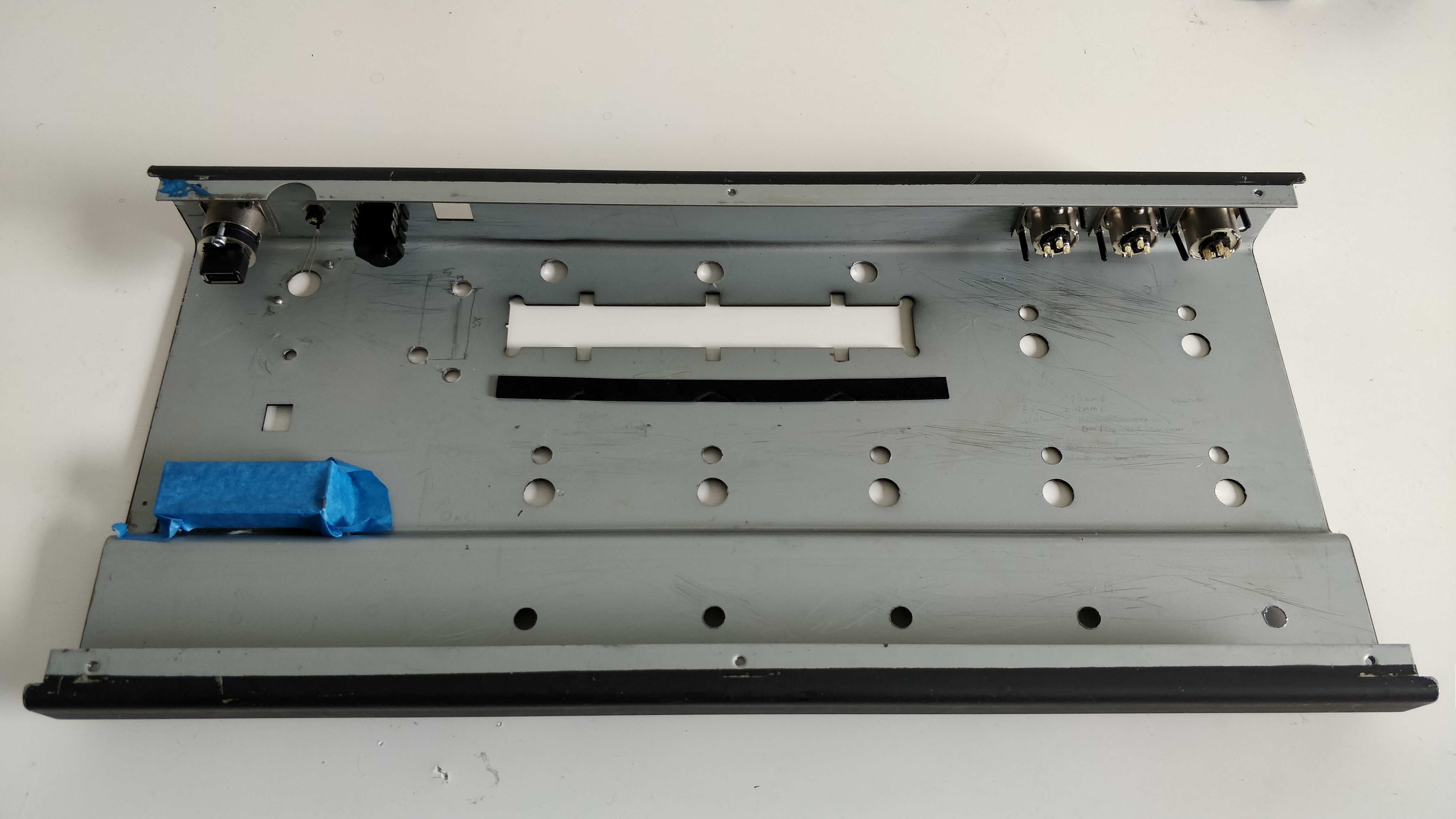
I test fitted the rear chassis hardware and everything fits great so on to the next stage - painting!
![]()
(The additional, accidental, hole can be seen to the right of the screen cutting in to the word 'volume')
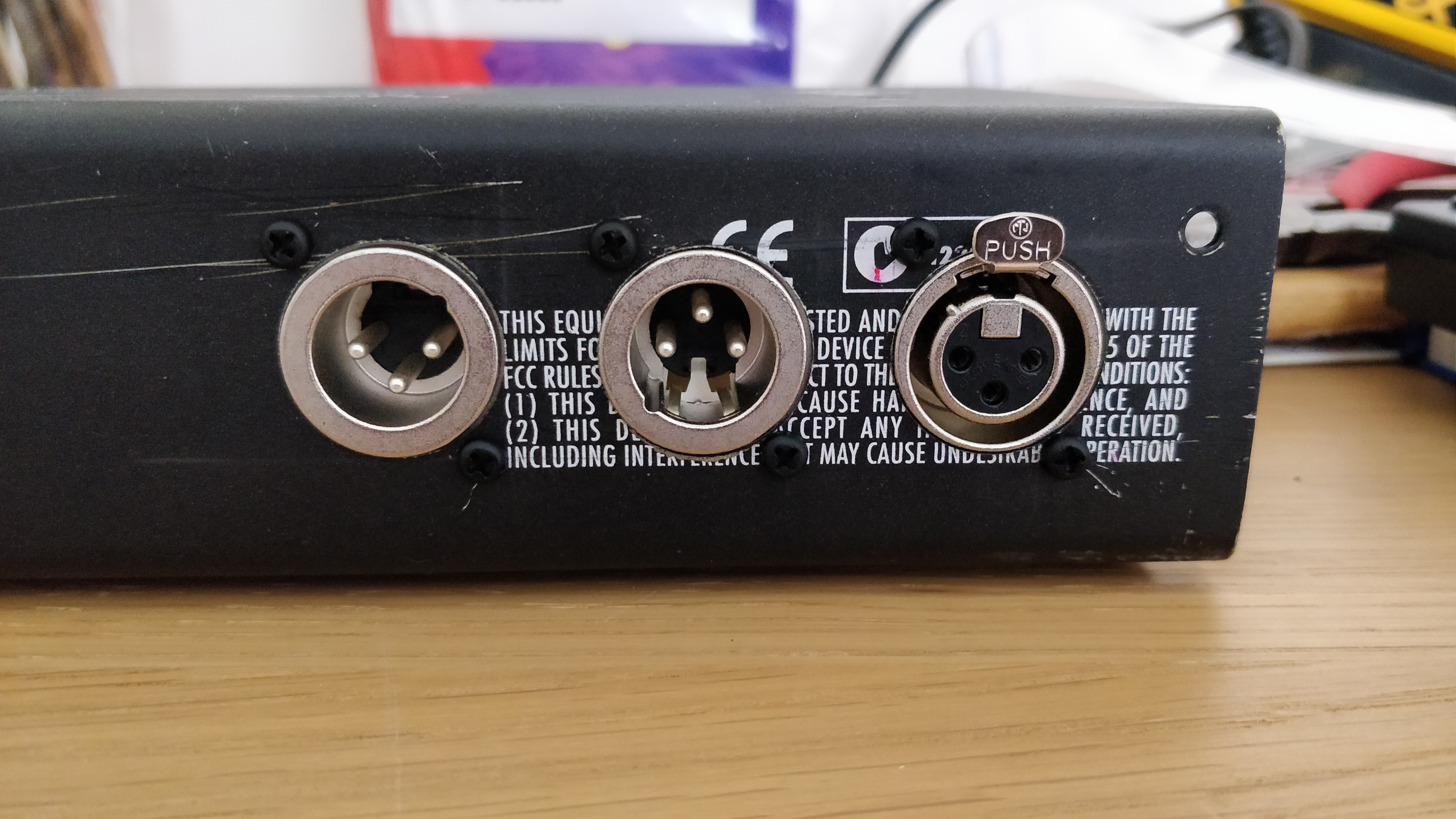
![]()
![]()
(The Neutrik D XLR connectors - and yes I realise I have one inverted....)
![]()
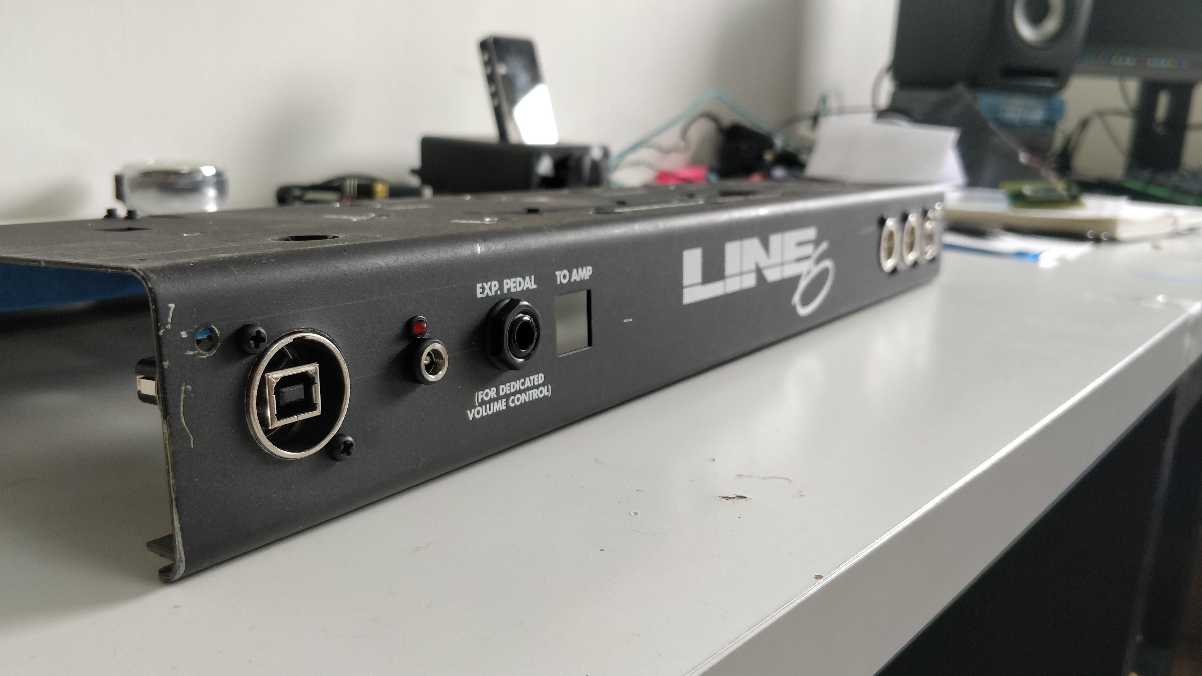
(USB, power, and external expressions jacks - the expression jack hole was actually already there. The square hole previously had the Line 6 RJ45 connector to go to the amp it was controlling, this slot will now also have an RJ45 socket in it which is part of the Qwiic i2c differential breakout to act as an 'extension' socket)
-
[Component Choice] Chassis
05/14/2020 at 11:42 • 0 commentsThe choice of a chassis to which everything would be mounted was initially one of the most difficult choices, but looking back my choice of chassis seems incredibly obvious and I'm not sure why I didn't go down this route from the start!
The chassis requirements were:
- Large enough to hold at least 10 footswitches
- Robust enough to withstand being stomped on
- Straight-forward to cut all holes etc in using hand tools/hand power tools at home
Not a particularly complicated list, but finding a chassis which was large enough for at least that many footswitches without them being over-cramped was tricky.
Drilling holes for footswitches and LEDs wasn't an issue, but the chassis was going to either large or non-round holes cut in it for access to the USB port, XLR sockets (a later addition), and screens. The large holes I would be able to do with either a hole-saw or knock-out punch but it was the non-round holes that was causing me issues.
I resigned myself to having to seek some assistance from a local machine shop to cut the non-round holes when a thought occurred - why not just 're-cycle' an existing foot controller?
An existing unit would:
- Be already ergonomically designed - and large enough - for a large number of footswitches
- Generally have pre-cut holes for USB connections and - more importantly - displays
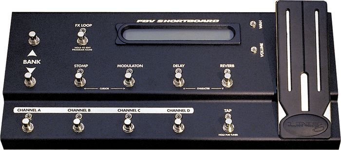
A short search lead me to what I have ended up with - a Line 6 FBV Shortboard MK1
![]()
This ticked all the boxes and even had an expression pedal built in!
I managed to find one on eBay for about the same price I was going to pay for a generic sheet metal chassis so snapped it up.
The layout of the footswitches is perfect for what I have in mind for functions and - as a total co-incidence and not planned at all - the 14-segement displays I was planning on using fit perfectly within the display 'window' of the unit so this would not have to be altered at all!
The rear of the unit is the perfect height to accommodate some Neutrik D sized connectors for XLR and USB, and already included a few socket holes I could use for other ports.
All in all, with a few relatively minor modifications I now have an excellent chassis for which to build STJORN upon.
-
[Component Choice] Teensy 3.2 Micro-controller
05/14/2020 at 11:27 • 0 commentsThis whole project started when, after hearing the name for a long time, actually realised what an Arduino micro-processor could actually do. A short investigation lead to the discovery that lots of people were creating MIDI controllers using these controllers and that is was a fairly straight-forward thing to do.
The huge number of Arduino boards available was initially a little overwhelming, but on narrowing down what I actually wanted the STJORN controller to do a clear choice rose above the usual UNOs, Leonardos, etc.
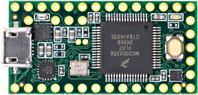
The choice was a PJRC Teensy 3.2.
This tiny tiny board had everything I required for this project:
- Tonnes of digital inputs for footswitches (34 inputs to be precise)
- Plenty of analog inputs so I could use external expression pedals
- Built in, ready-to-go, USB MIDI
- This was probably one of the main reasons for choosing the Teensy to be honest
- Plenty of processing horsepower so that I didn't need to really worry about it
- i2c and SPI
- Very small form factor
- Cheap! (around £18 in the UK)
![]()
One was purchased and within hours of really using an Arduino controller for the first time, I was already able to send and receive MIDI over USB!
I now have two Teensy 3.2s - one is on a breadboard and is used for testing circuits and generally playing around, and the other is for the STJORN itself.
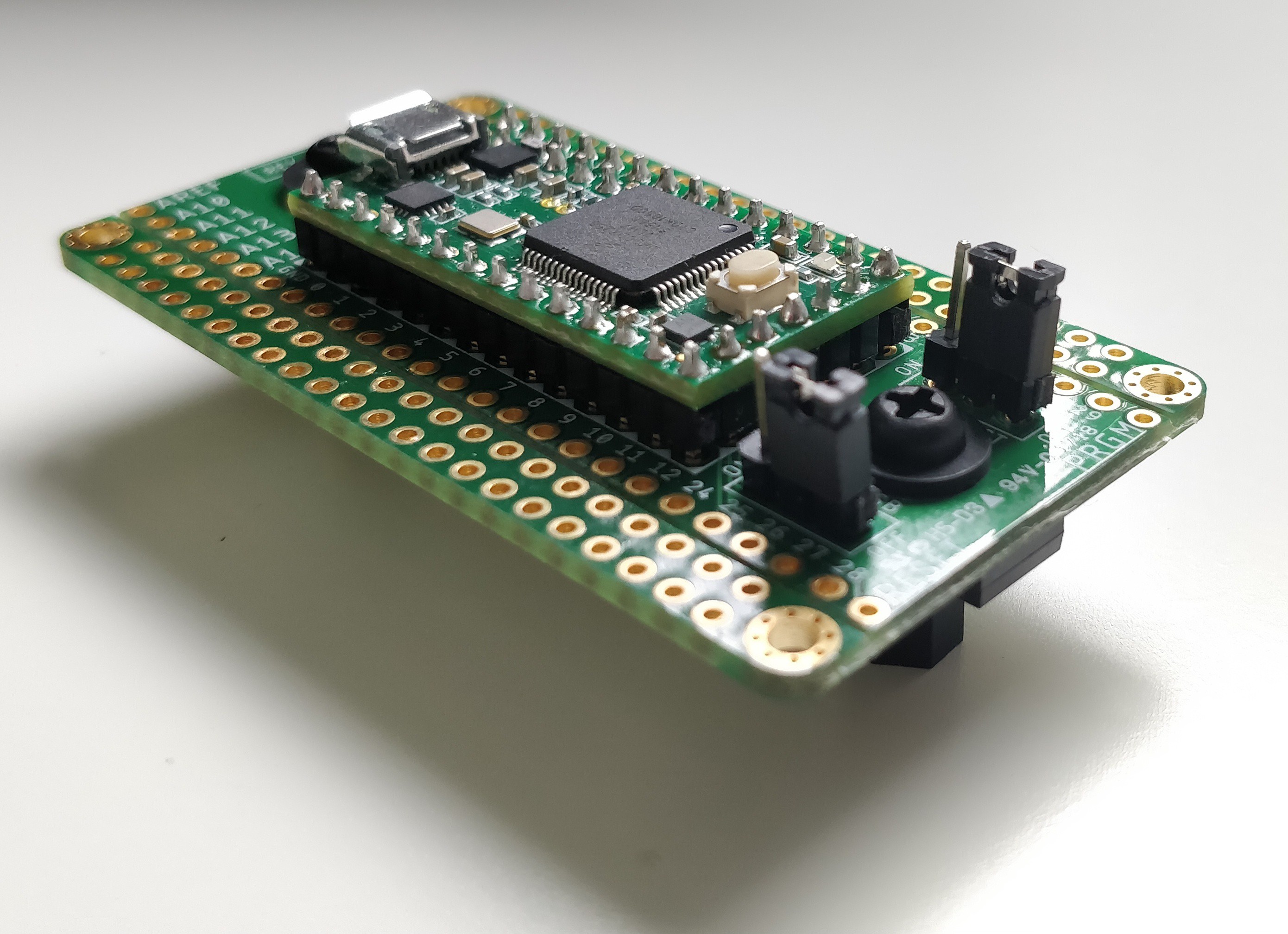
For the board to be mounted in the STJORN, I have used a Tall Dog Teensy 3.2 Breakout to mount it. This not only provides easy access to all of the pins - some of which on the Teensy 3.2 board are located underneath with no direct access - but also some handy mounting holes to attach the board to the chassis. Here is the - actual one to be used in STJORN - Teensy 3.2 mounted to the breakout:
![]()
This little workhorse is going to do perfectly for this project.
STJØRN
Custom MIDI controller for a live, VST based Guitar and Tracks rig