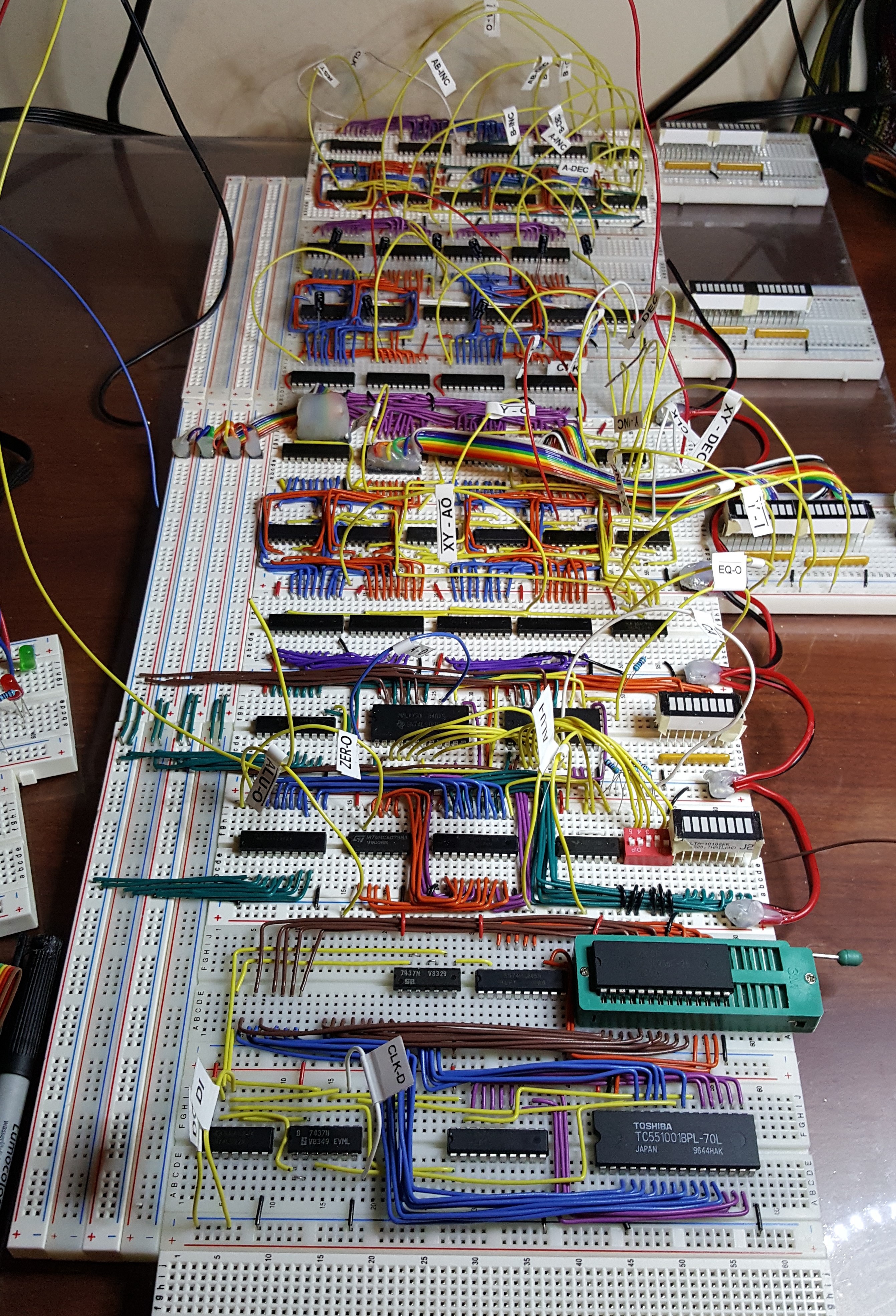
I'm back from my little vacation in Vegas and have been busy building. I bought a sheet of 1/4" acrylic to mount all the boards together. I was tired of trying to clip them together with wires or headers. It's working nicely. I wanted to start running all my control lines into their positions so I can get rid of all those big loopy wires. I couldn't do that until I had a place for them all to go (the empty board at the bottom). I have room for another column of breadboards on the left side of the data bus.
I finished the RAM / ROM module and tested it. I used a ZIF socket for the 32K ROM chip to make reprogramming quick. I have more of them for the microcode ROM's. The address bus is removed in the picture as well as the data bus connections to the RAM ROM module. The RAM / ROM module is technically "external" to the CPU and my DI control line would be the R/W output. The DI control line would control the tri-state buffers between the internal and external data bus.
 2-Zons
Discussions
Become a Hackaday.io Member
Create an account to leave a comment. Already have an account? Log In.
looking really good!
Are you sure? yes | no
Wow! Looking nice! 8^)
Are you sure? yes | no