 Jude Frie
-
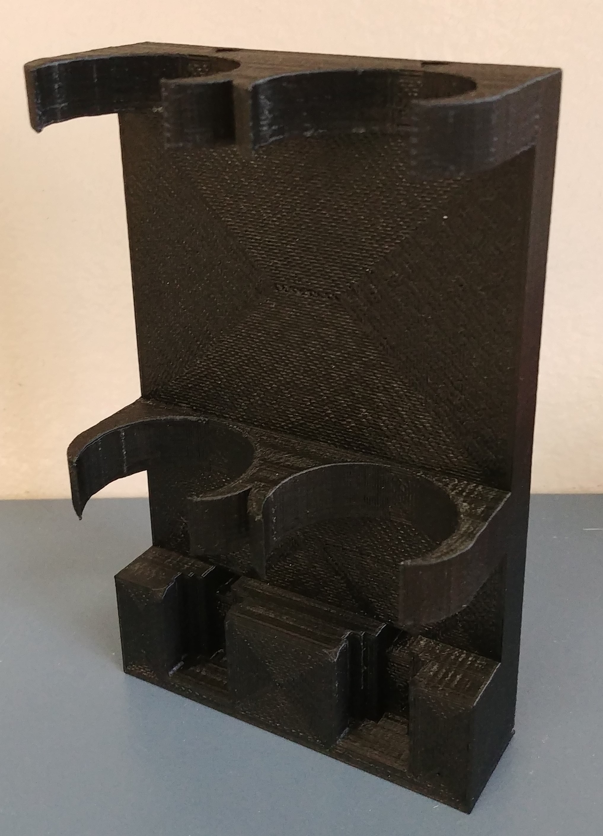
13D print the bottle housing
The housing should be printed on its back, that is, on the side opposite to the bottle slots. No structural supports are needed for this print. The printer filament used for this design was PLA, however, any filament should work equally well. If the 3D printer being used is too small to print the housing in one piece, the housing can be sliced, printed in several pieces, and epoxied together. The choice of triangular wire channels was made so that no structural supports would be required for the print.
![]()
-
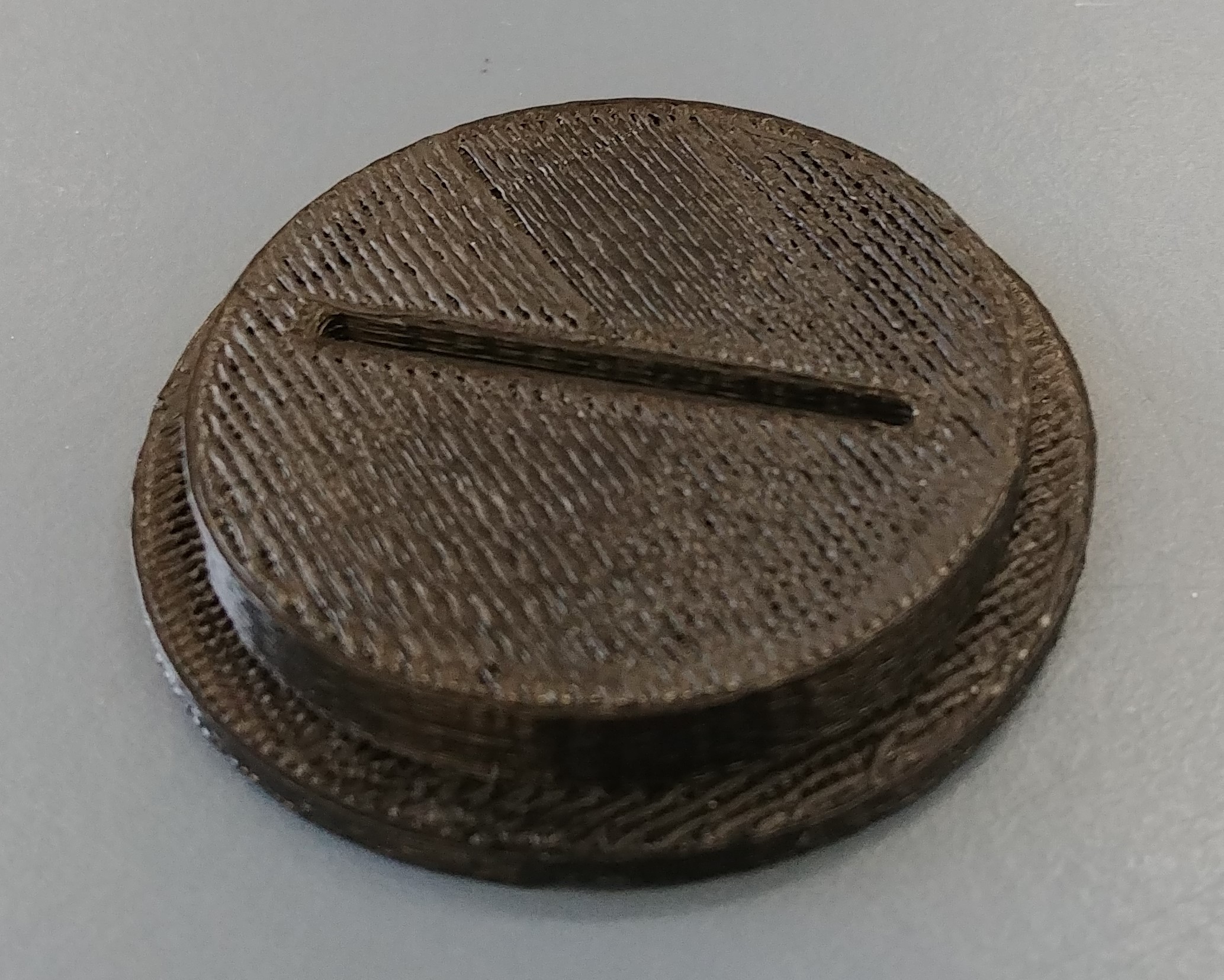
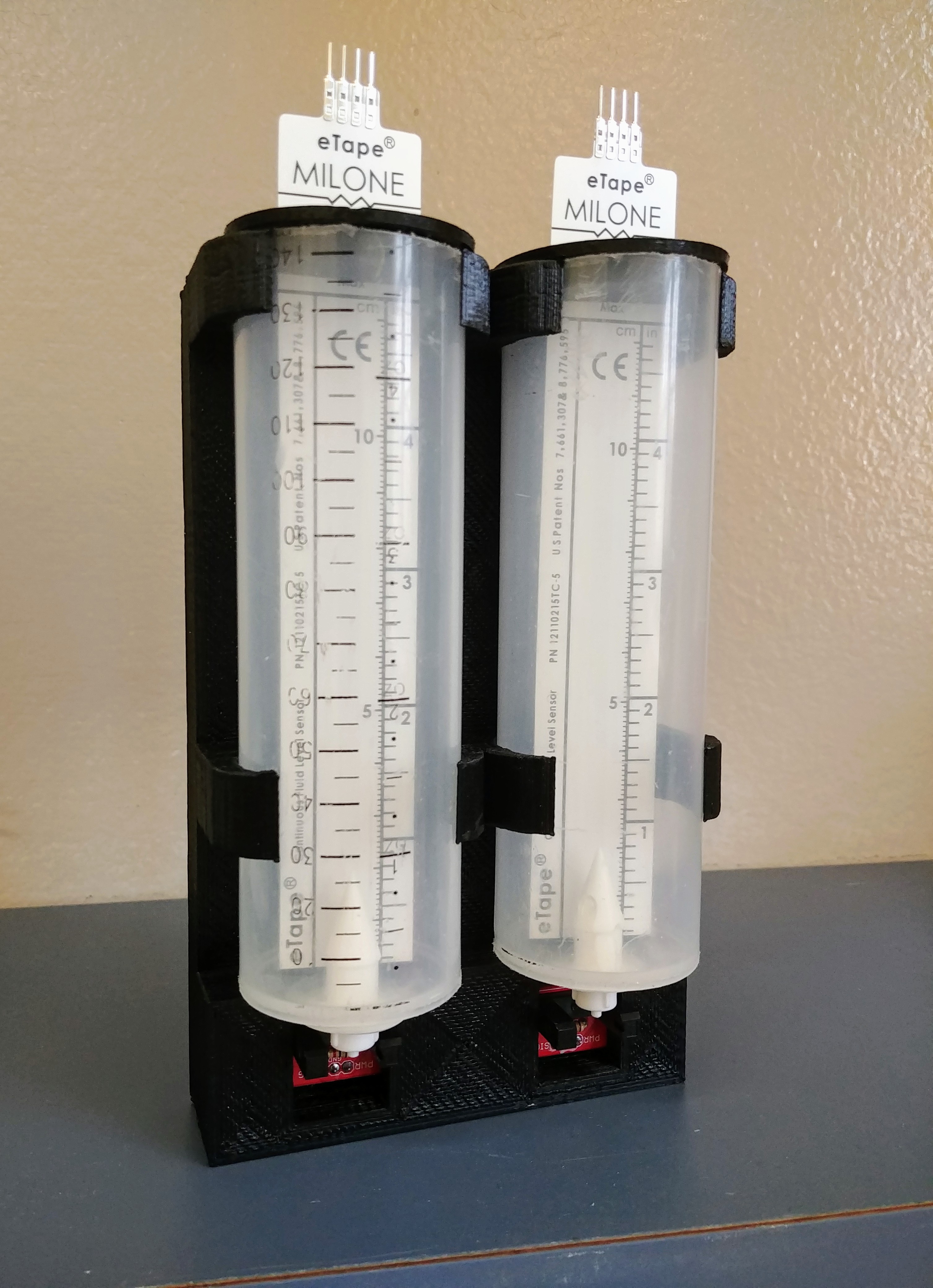
23D print two of the bottle caps
These are designed to keep the hydrostatic depth sensors straight as they are highly error prone when bent.
![]()
-
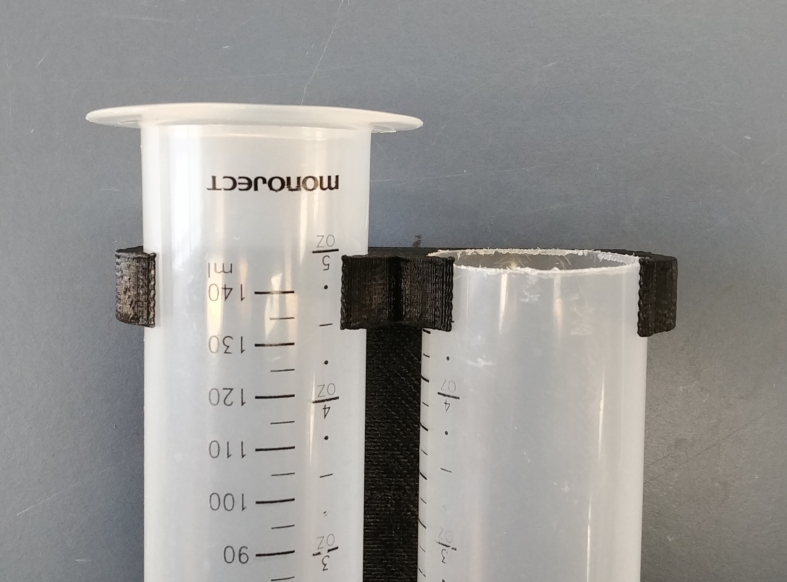
3Cut syringe tops
Remove syringe plungers and cut the top of the syringe off to be flush with the top of the housing.
![]()
-
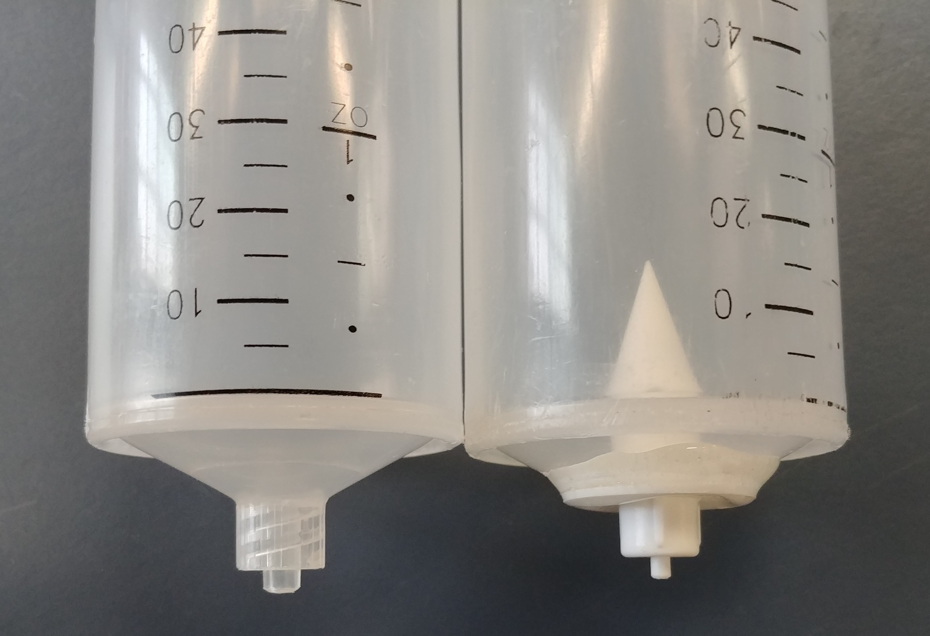
4Cut syringe bottoms and replace with valves
Cut the bottom of the syringe off and use epoxy to attach a plastic valve and let dry.
![]()
-
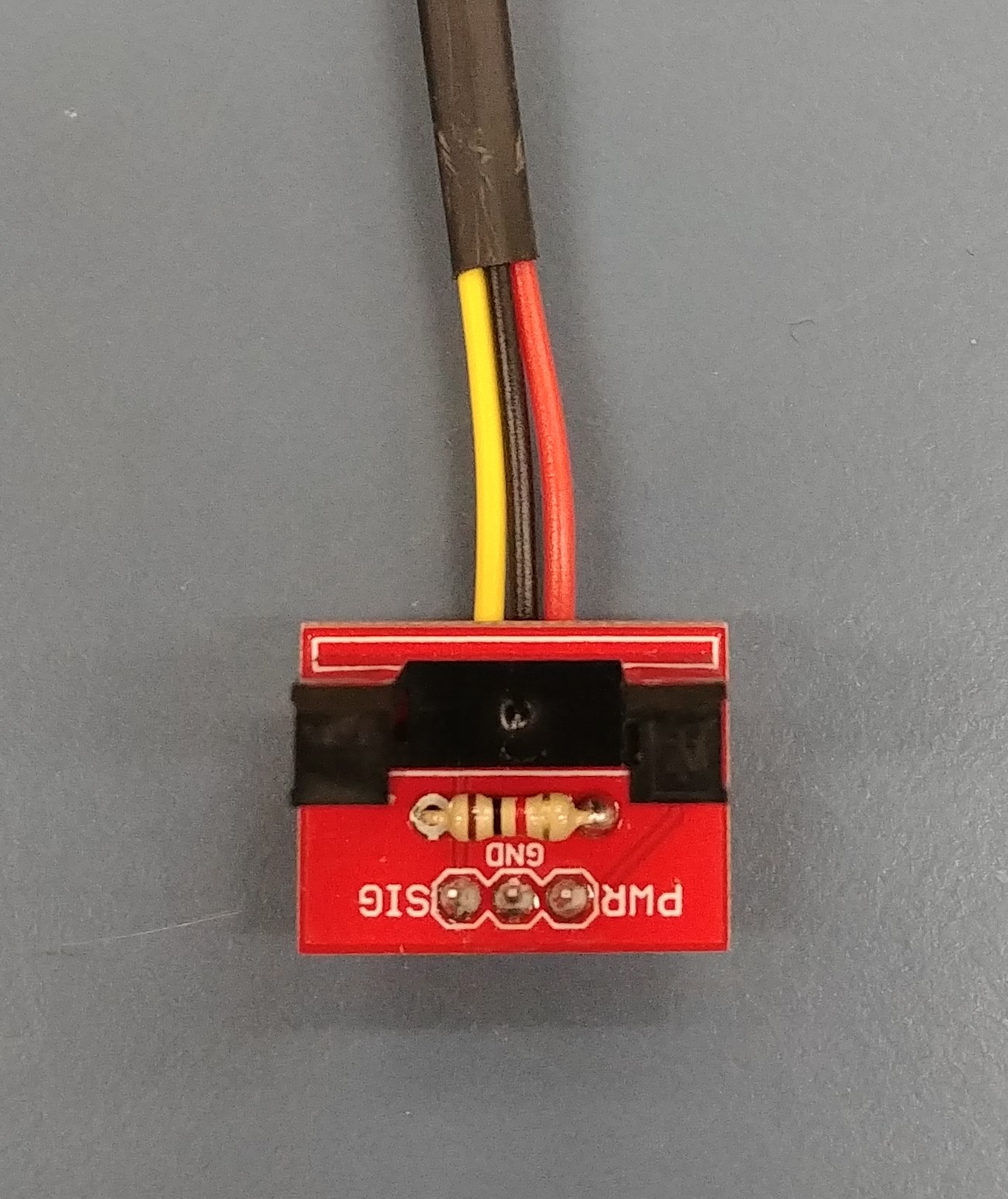
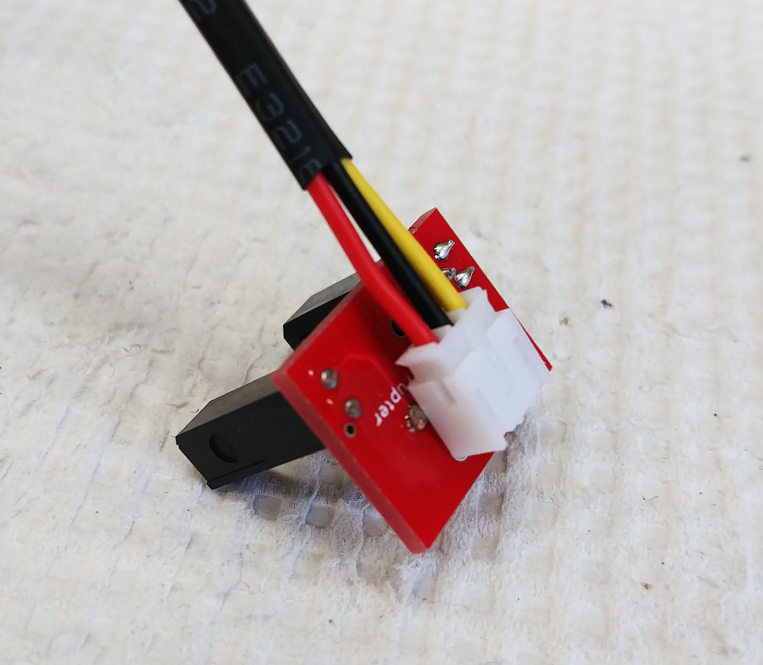
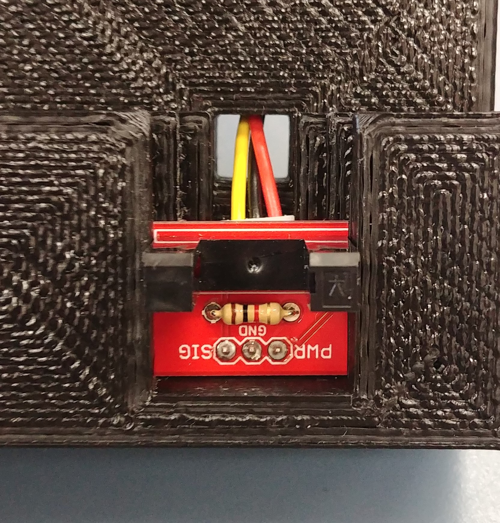
5Assemble photodetectors
Solder the photo interrupter, a 1K Ohm resister, and the JST Jumper 3 Wire Assembly to the photo interrupter breakout board.
![]()
![]()
-
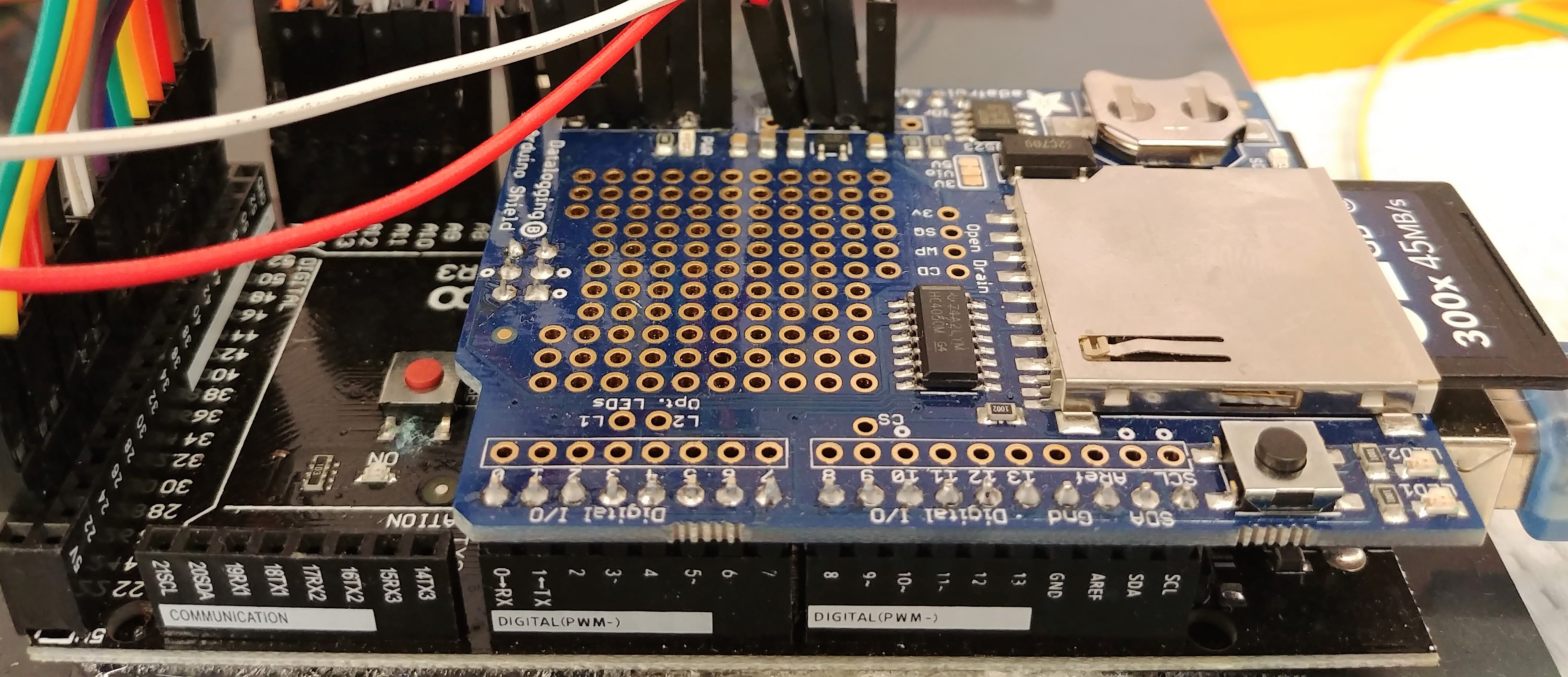
6Attach SD shield to Arduino
Place the male headers that are provided with the shield into all the Arduino’s female headers (long side down). Also place the 2x3 female header provided into the 2x3 pins in the center of the board. Line up the pins with the SD shield and press together. Now solder the pins to the SD shield.
![]()
-
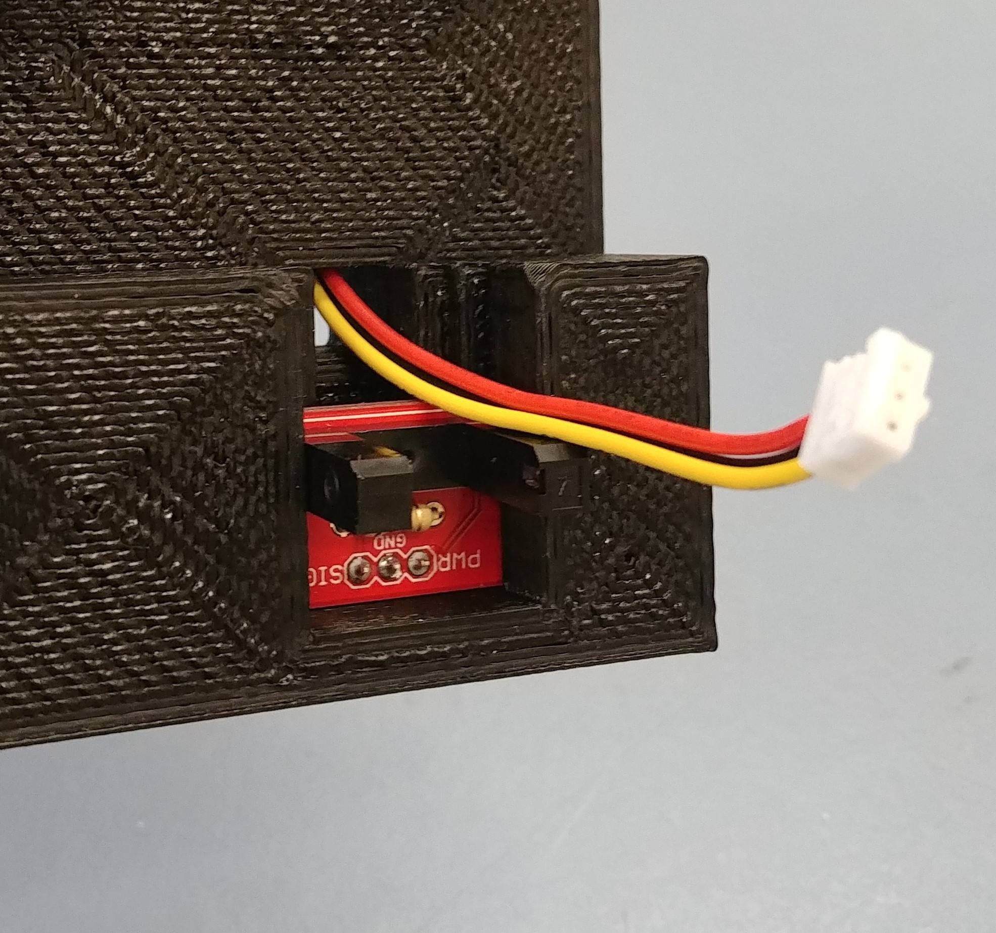
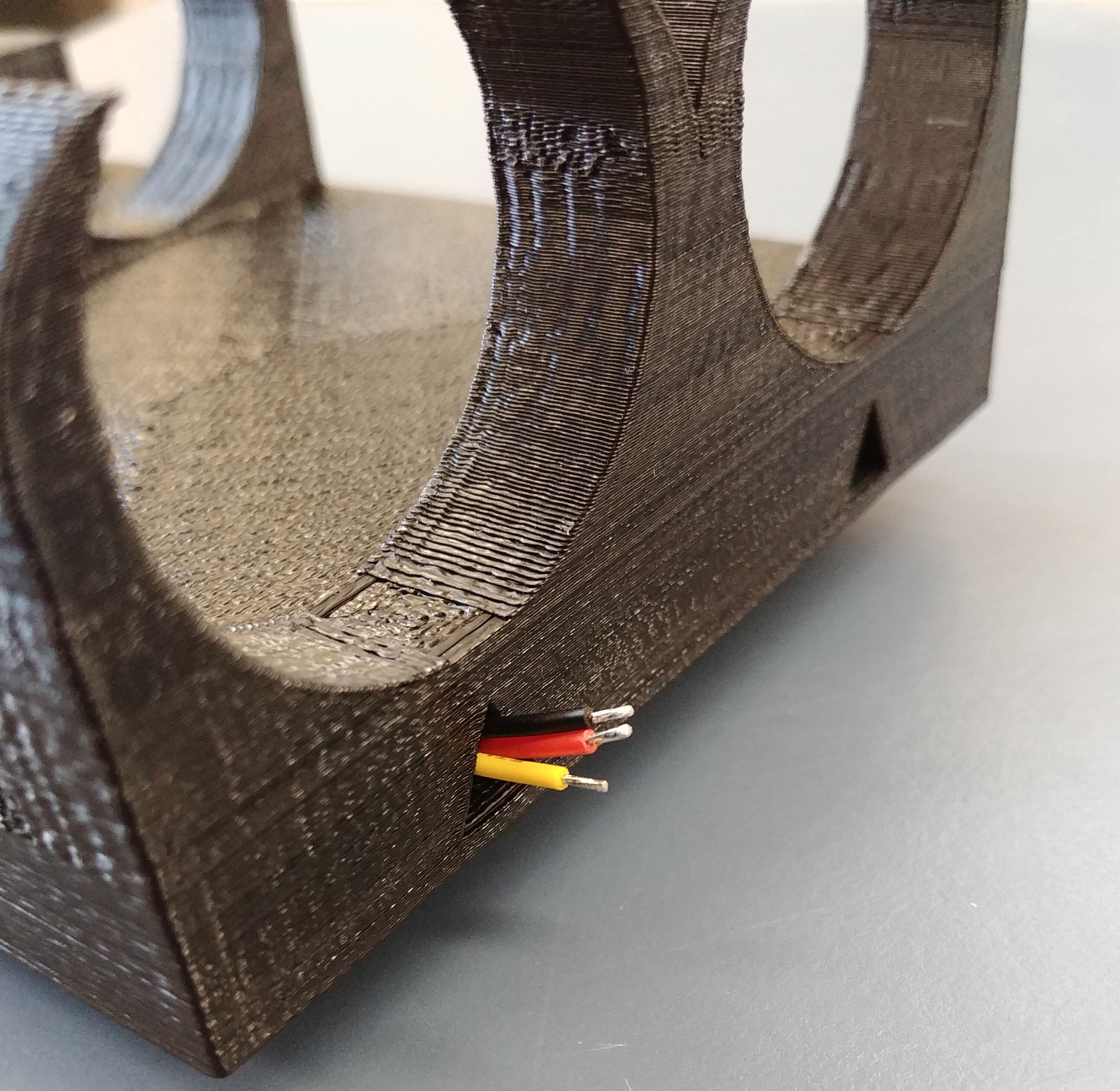
7Connect the photodetectors to the Arduino
Place the photo interrupters into their slots on the bottle housing. Run the 3 wires up through the triangular channel of the housing and out the top. Solder additional wire to extend these wires as much as desired (this will dictate how far the bottle housing can reach away from the Arduino, something to consider when powering several assemblies off a single Arduino). Attach the red wire to the Arduino’s 3.3V power output, the black wire to ground, and the yellow wire to any of the 54 digital channels. For several assemblies, it is a good idea to organize the inputs and outputs on a solderable breadboard.
![]()
![]()
![]()
-
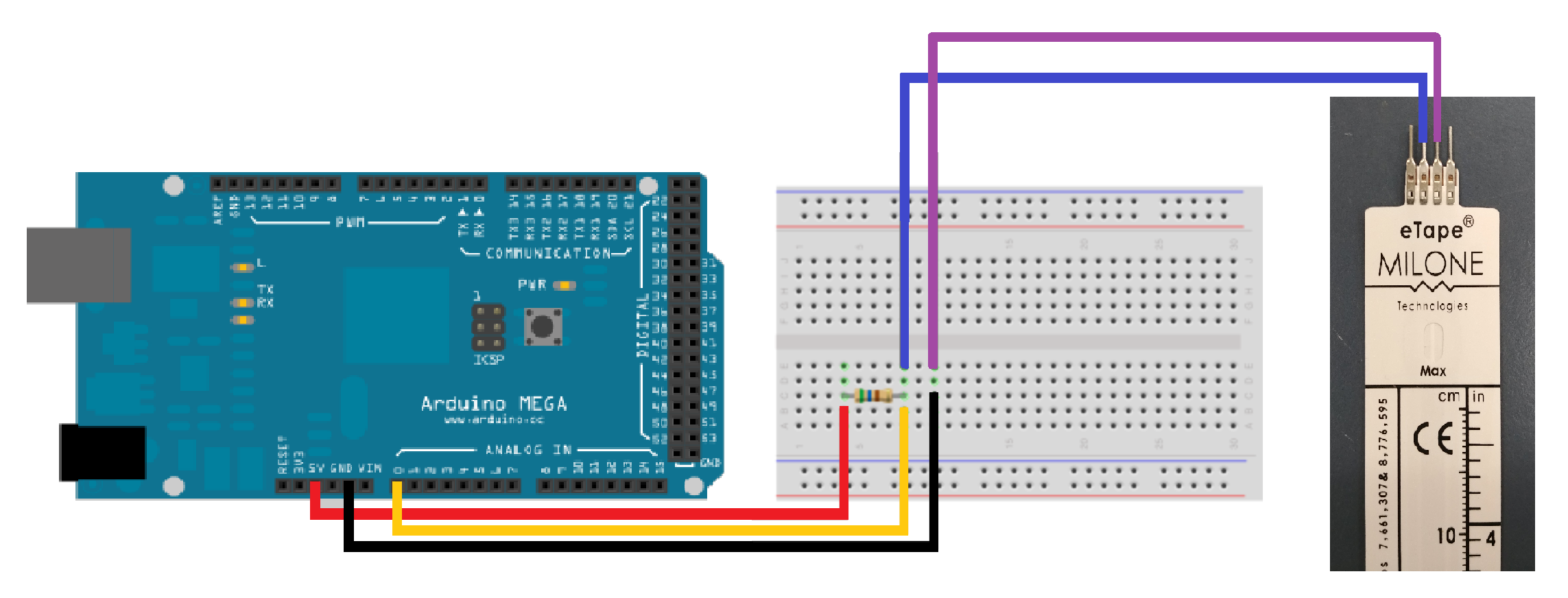
8Connect the depth sensors to the Arduino
Connect pin 3 of each depth sensor to ground. Connect pin 2 of the depth sensors to one of the 16 analog inputs. Place a 1K ohm resistor between the Arduino’s 5V output and the analog pin chosen.
![]()
-
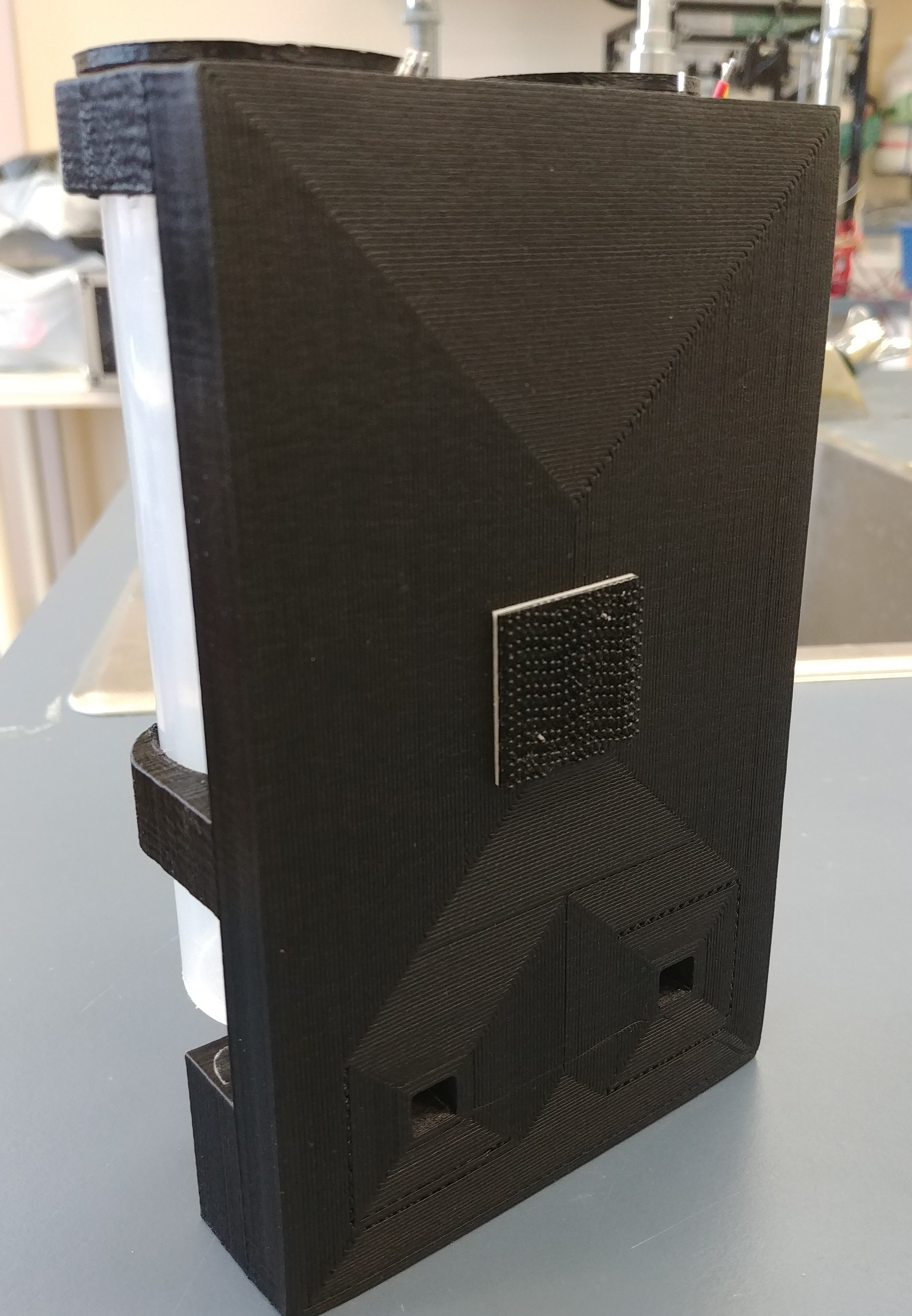
9Assemble
Place bottle caps on bottles and bottles into the housing. Slide depth sensors into bottle cap slots. Put one half of a picture hanging strip on the back of the housing and attach the assembly to a cage with the second half. Hanging strips were chosen as an attachment method to make the Automated Two-Bottle Choice Test compatible with as many different cage-types as possible.
![]()
![]()
-
10Calibrate depth sensors
Flash the calibration.ino code onto the Arduino and follow the commented instructions. Fill the calibration values for each sensor into the TwoBottleChoice.ino code i.e. ZERO_VOLUME_RESISTANCE, CALIBRATION_RESISTANCE, and CALIBRATION_VOLUME. The TwoBottleChoice.ino program includes the code to run the maximum number of assemblies that one Arduino mega can handle (Max is 8). However only the code for one assembly is uncommented. That is, all that needs to be done to run additional assemblies is uncomment the additional portions of code for each.
An Automated Two-Bottle Choice Test for Rats
An open source testing apparatus that uses photodetectors and depth sensors to measure and record rat drinking microstructure.
Discussions
Become a Hackaday.io Member
Create an account to leave a comment. Already have an account? Log In.