A Controller for a SCARA Arm
To make the experience fit your profile, pick a username and tell us what interests you.
We found and based on your interests.
SCARAAreaCals.odsapplication/vnd.oasis.opendocument.spreadsheet - 27.29 kB - 02/18/2019 at 00:25 |
|
|
Final.pngPortable Network Graphics (PNG) - 29.84 kB - 02/18/2019 at 00:25 |
|
|
TestSCARA.ctext/x-csrc - 1.90 kB - 02/18/2019 at 00:25 |
|
|
ControlTest.hx-chdr - 1.71 kB - 01/28/2019 at 12:24 |
|
|
ControlTest.fdfd - 14.88 kB - 01/28/2019 at 12:24 |
|
|
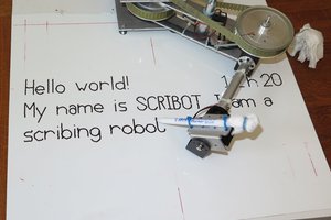
Now that I have a SCARA machine (okay its made of MDF and wobbles like a clock spring), I can actually test the code.
Based on today's hack getting the SCARA working there are a few things I need to do:
This is the GUI at the moment:
The Motor 1 and Motor 2 parameters are now only used for the SCARA graphics. In general use (of the GUI) it is probably not of interest. You can always create a custom program for this.
The code at the moment turns the Spindle On and Off (i.e. M3 and M5) as if it is the Laser. But GRBL uses PWM (as does my Laser module) which is controlled by Spindle Speed (i.e S####). GRBL assumes a S0 is off and S1000 (or higher) is maximum power. So the initialisation code should set the Spindle Speed if the gCode does not set it.
GRBL also complains if the Feed Rate is not set in the initialisation Code.
At the moment my initialisation code is "G17S1000F600".
Serial speed is based on the xForms' idle call back. If the GUI is not busy then the idle call back is called at least once every 10 ms. While this is not slow with regard to gCode movements, it does look like its is slow when (say) checking GRBL's settings with "$$".
Perhaps a separate thread would be a better approach.
So still quite a lot of coding work to do.
AlanX
Created a GUI version of gCode2SCARA, call SCARA2gCodeTest (I seem to have messed up the name!). The GUI has the added advantage of communicating via a serial port (real or USB) to talk directly to Grbl:
Here is a typical input gCode file (that can been filtered using the input tolerance slider):
And the output (SCARA) gCode (that can also be adjusted to smoothness):
Note, I have deliberately set the offsets so that port of the file is out of bounds.
Just for fun, the stepper motor steps per revolution can be reduced (from 19200 to 3200):
Some minor bugs. with the filter code. Exporting some blank lines.
---
More bugs!
Implemented a Feed Speed control for the SCARA (it is a laser engraver after all). UV space is non-linear so need to issue an updated SCARA feed speed more often.
I have assumed Grbl is set to 100 steps per mm for each axis, so his needs to be added to the GUI interface.
---
If I abort Grbl while running, it locks it self. Even after soft-reset it needs a $X to unlock.
---
Updated the serial code to accept ttyACM0-7 as the AtMega2560 Pro-mini uses a different RS232 chip.
---
Otherwise, all good, AlanX
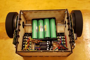
Here is the Stepper Motor Driver Board:
Almost no documentation in the Internet on this board! It is cheap and I have used it before.
Mapping/tracing the Nano pins I get:
There are also:
One fault with these boards is that the shunts to control the micro stepping does not work. I added these 10k pull-ups to fix the problem:
Pre-processing "cartesian" gCode with gCode2SCARA allows the use of Grbl for a SCARA arm (UVZ type). This what I would recommend to get started.
Is some code that I wrote that will also do the job.
Is some more code that I wrote (but needs some work of the interpreter) that could also do the job. I intend to finish this code off to work with gCodeFilter and gCode2SCARA at some point of time.
If you have not realised, gCode2SCARA is a command line program program designed to be used via a batch file. Here are the current options:
-i Input File
-o Output File
-t XY Space Tolerance (mm)
-s UV Space Tolerance (full steps)
-xc gCode X Offset (mm)
-yc gCode Y Offset (mm)
-L1 Arm 1 Length (mm)
-L2 Arm 2 Length (mm)
-M1 Motor 1 Steps
-M2 Motor 2 Steps
This project could benefit from a "Visual Windows" programming approach, so probably time to look at what is available for Linux that is simple to use.
AlanX
The code is basically done, some check work remains.
Here is the XY space (filtered from 45984 points down to 2029 points, i.e. -t 0.01):
And here is the UV Space (-s 0.01 and 2029 points, no additional inserted point):
The UV plot (i.e. the output) however does not consider the step resolution (i.e. UV space is floating point). The plot seems to be in the wrong quadrant (it is possible as I have changed the reverse kinematics mathematics).
I will will have to create another plot window to show the effect of step resolution.
So just some tidy up remains.
Yesterday I was helping my partner clean her house after the floor boards were sanded and varnished. So no work!
The code checks out, need to do something better for when the arms will not reach, currently just set the location to (0,0). Better to make it obvious in the imagery.
Checked that the reverse kinematics works in all quadrants. Here is an example with the arm movements shown:
Added a Bressenham trace (yellow/green), in this case for M1 and M2 equal to 400 steps each (note, the image has been shifted to exceed the limits of the reach of the arms):
Here is the case for M1 and M2 equal to 1600 steps (1/4 micro-stepping):
And finally M12800 (1/32 micro stepping):
Note that G0 (rapid movement is an arc rather than a straight line).
So other than modifications required (discovered) when I actually use the code on a machine, it is done.
AlanX
Its a rather "long road" to write a Grbl replacement (perhaps later), but converting gCode from XYZ to UVZ is not. I have seen that someone has already done this on the Internet (sorry I have lost the link). So basically after conversion you can use Grbl instead.
Perhaps I am wrong but Grbl does not appear to handle UVZ coordinate systems.
I already have a gCode Filter project that can be co-opted into service.
After filtering the gCode to remove "redundant" segments (i.e. the main function of gCode Filter), I only need map the UVZ space and to insert the critical points.
I have made a start, set up two graphical results windows, one for XY space and the other for UV space. Still about a days coding left to complete (wishful thinking perhaps?).
One of the issues for construction of a SCARA is the bearing. Nearly all the projects I have looked at are DIY. It would be nice to get something reasonalbe (lazy susan bearings are pretty bad!) off the self.
For a big project a car one piece stub axle looks like an option (~AUD50):
After a bit of searching I found good candidate, a bicycle front wheel hub:
Are you excited yet? AlanX
After playing with the Options presented in my first post, I have decided Option 1 is the best. Why? It should have the least number of the expensive reverse kinematic calculations. Consider a very coarse tolerance (=128):
Note that the UV space (blue lines) has only 6 points (the straight lines between them are Bressenham lines).
Now the medium tolerance case (=32):
Here there is only 13 reverse kinematic calculations.
Now the very fine tolerance (=8):
Here there is only 25 reverse kinematic calculations.
Finally ultra fine tolerance (=1), has 67 calculations:
Although the number of reverse kinematic calculations are a minimum, there still may be advantage is fast (integer?) methods. The CORDIC algorithm comes to mind, especially for the ATAN2() and sqrt() functions. ArcSin/ArcCos should also be possible.
Here is my version of Rect2Polar (i.e ATAN2() and sqrt()) using short (i.e int16) integers:
// Include libraries
#include <stdio.h>
#include <stdlib.h>
#include <stdint.h>
#include <string.h>
#include <math.h>
#include <stdbool.h>

void rect2polar(short X,short Y,short *R,short *A)
{
  // ATAN_Table is the values of ATAN(1/(2^i))*400*32/2/Pi micro-steps
  short ATAN[12]={1600,945,499,253,127,64,32,16,8,4,2,1};
  short i,Xnew,Ynew;

  (*A)=0;
  if (X<0) {
    (*A)=200*32; // 180 degrees
    X=-X;
    Y=-Y;
  } else if (Y<0) {
    (*A)=400*32; // =360 degrees
  }
  for (i=0;i<12;i++) {
    if (Y<0) {
      // Rotate CCW
      Xnew=X-(Y>>i);
      Ynew=Y+(X>>i);
      (*A)=(*A)-ATAN[i];
    } else {
      // Rotate CW
      Xnew=X+(Y>>i);
      Ynew=Y-(X>>i);
      (*A)=(*A)+ATAN[i];
    }
    X=Xnew;
    Y=Ynew;
  }
  // Adjust for gain (=X*0.607252935)
  X=X>>1;
  (*R)=(((((((((((((((((X>>2)+X)>>2)+X)>>1)+X)>>1)+X)>>2)+X)>>1)+X)>>2)+X)>>1)+X)>>3)+X;
}
int main(void) {
  short A,R,X,Y;

  X=-439*32;
  Y=-439*32;
  // R=621*32 max
  rect2polar(X,Y,&R,&A);
  printf("Rect2Polar x %8.3f y %8.3f ang %8.3f hyp %8.3f\n",X/32.0,Y/32.0,A*360.0/400.0/32.0,R/32.0);
  printf("atan2()    x %8.3f y %8.3f ang %8.3f hyp %8.3f\n",X/32.0,Y/32.0,360+atan2(Y,X)*180/M_PI,sqrt(X*X+Y*Y)/32.0);

  return 0;
}
Here is the result:
$ ./ShortCAtan
Rect2Polar x -439.000 y -439.000 ang 225.028 hyp 620.812
atan2() x -439.000 y -439.000 ang 225.000 hyp 620.840
$
So about 4 digits of accuracy with 16 bit integers.
I reworked the mathematics to suit CORDIC:
Here is my ArcSin CORDIC:
// This version works properly but has a multiplication in the main loop
short arcSin(short R, short S) {
  // ATAN_Table is the values of ATAN(1/(2^i))*400*32/2/Pi micro-steps
  short ATAN[12]={1600,945,499,253,127,64,32,16,8,4,2,1};
  // SEC[i]=(int)((1/COS(ATAN(1/(2^i)))-1)*(2>>14)+0.5);
  short SEC[15]={6787,1935,505,128,32,8,2,1,1,1,1,1,1,1,1};
  short i,Rnew,Y,Ynew,A;

  Y=0;
  A=0;
  for (i=0;i<=11;i++) {
    if ((Y<S)&&(A<100*32)) { // 90 degrees
      // Rotate CCW
      Ynew=Y+(R>>i);
      Rnew=R-(Y>>i);
      A=A+ATAN[i];
    } else {
      // Rotate CW
      Ynew=Y-(R>>i);
      Rnew=R+(Y>>i);
      A=A-ATAN[i];
    }
    Y=Ynew;
    R=Rnew;
    S=S+((S*SEC[i])>>14);
  }
  return A;
}
The down side of my ArcSin CORDIC is the multiplication inside the main loop. I remember I had to do the multiplication to avoid instability.
AlanX
Here is an example of the type of SCARA that I want to model:
Two X and Y arms and linear Z (say):
L1 = 200mm
L2 = 150mm
Z = 150mm
Two stepper motors:
M1 = 400 steps (assume direct drive for the moment)
M2 = 400 steps(assume direct drive for the moment)
Also I want to use an Arduino Nano for the motion controller.
Ignoring the Z axis for the time being, the forward kinematics represented by (U,V) to (X,Y), where (U,V) are polar motor steps and (X,Y) are the "real world" cartesian coordinates:
The forward mathematics is:
Ignoring the Z axis for the time being, the reverse kinematics represented by (X,Y) to (U,V):
or
I have reworked the equations to:
R=sqrt(X*X+Y*Y)
CosA=(L1*L1+R*R-L2*L2)
SinA=sqrt((2*L1*R-CosA)*(2*L1*R+CosA))
U=atan2(Y,X)-atan2(SinA,CosA)
CosA=(R*R-L1*L1-L2*L2)
SinA=sqrt((2*L1*L2-CosA)*(2*L1*L2+CosA))
V=atan2(SinA,CosA);
The reason is that sqrt() and atan2() is a well known for embedded applications.
Two issues:
For example:
Note how straight lines in XY space are curves in UV space, and motor step resolution (in UV Space) maps into jagged steps in XY space.
(The plotted square is 125 mm x 125 mm, the arms are 200 mm and 150 mm, and the motors are both 400 steps.)
Okay, the third problem is the need for gearing as the motor step resolution is too low.
---
I have tried three methods for accurate XY space to UV space.
Segment the UV space curves into straight lines (by inserting points) using a tolerance (i.e. if the tolerance is not exceeded then a point need not be inserted):
This works well for feeding the mapped UV space directly into a Bressenham's Line Algorithm (i.e. Grbl).
This option could be pre-processing or on-the-fly (i.e. on the motion controller).
Nearest UV space point mapping (path search):
The method seems to be efficient (with look up tables) and path search algorithm can certainly be improved. This algorithm would replace the Bressenham's Line Algorithm (i.e. exports to the motor controller hardware directly).
This option would be on-the-fly (i.e. replaces Grbl).
This options breaks the XY space lines into very small segments that are then mapped to UV Space. Duplicate UV space points can be removed. Simple but inefficient.
Pre-processing only.
AlanX
Create an account to leave a comment. Already have an account? Log In.
Yes and no. I assume 3D printing need to consider volume? My code "distorts" gCode which the SCARA "undistorts". That is what "xy space" and "uv space" is all about. For example feed speeds are distorted so I need to insert feed speed adjustments between segments (if necessary of course). Something I have to do for a laser. So there is quite a bit to do for 3D printing. I was not looking at 3D printing but if there is an interest I can look at it. Its perhaps a day of research and a few hours of coding. Testing is the biggest problem as I don't have a 3D printer. I currently compile for Linux at the moment but if pushed I can compile for Windows.
On the plus side my code filters out unnecessary points which I suspect would be a pretty big bonus for most applications.
One of the learning of my prototype SCARA is the need for some friction in the joints to dampen oscillation. This opens the door for sliding type bearing surfaces (as opposed to ball bearings). Home made telescopes (usually dobsonian type) for example use teflon and textured laminate "tape" as bearings. Even wood on wood with beeswax lubricant is been considered at the moment! Perhaps a cycloidal gear/joint?
AlanX
404s? Perhaps I am blocked. Found it. Even with the "Blah" between the links, it was still combined.
Check the <HTML> code as you may have inserted in the middle of an <AREF>.
Yes, the code "scarakins.c" is okay but I am beyond that now.
---
I am looking at "damping" at the moment because 1/16 micro-step direct drive is practically useless. It "wobbles" like a clock spring. With gearing and say half stepping it will be much less of an issue. As I want to use GRBL and LASER, the only option I can see is mechanical "braking" (i.e. a felt disk between the arms?).
If I code my own GRBL I could use PID.
Basically I now know why nobody uses direct drive steppers and micro-stepping for SCARA!
Its a difficult problem to fix.
AlanX
@Simon Merrett has a nice nema 17 stepper harmonic drive project on here: #Strain Wave Gear with Timing Belts Inline reduction with just a couple components and low backlash.
I also have a planetary gear system you could use, and if you print the outer in something stiff, and the sun gears in nylon, also nearly no backlash.
I don't know what was going on with the links. I cut them, repasted them, and they did the same thing. I removed the website link and kept the github.
Thanks for the link. I think there may be better compact gearing than mine such as the open HD project and Paul Gould's robot (apologies, no links but I'm sure you can find on HaD.io)
Now that was impressive! Lots of "lights" are going off in my head.
AlanX
Page not found?
---
My code converts cartesian gCode into gCode that fools the GRBL controller into working with a SCARA. I suspect my code is a bit more sophisticated.
I am currently building a simple laser SCARA to test the code.
I have not posted my latest work but I am currently working on making the SCARA move with a constant speed. As this is necessary for a laser to engrave cleanly.
---
Anyway I have spent the day finalising the SCARA build and setting up the controller.
You would think the controller would come with some (any!) documentation!
Its sorted now.
AlanX
Two bugs in Hackaday exposed here.
1) Two links in a row get combined. I have compensated.
2) FIrst reply to a post by the author results in a new post, and not a reply to the previous post. The end result is the poster never gets notified of the author reply. Workaround: Reply, reply again, delete first reply.
Pre-processing code to feed dumb systems is also a well explored topic here, but for the SCARA world I think you may have novelty. Good luck sir.
Whenever I hear SCARA, I think Scaro. Off topic, unless combined with your Dalek build. :)
https://github.com/machinekit/machinekit/blob/master/src/emc/kinematics/scarakins.c
And.. if you want something that 'just works' and need help implementing Machinekit... let me know. :)
Become a member to follow this project and never miss any updates
By using our website and services, you expressly agree to the placement of our performance, functionality, and advertising cookies. Learn More

 f4hdk
f4hdk
 sei
sei
 JP Gleyzes
 shane.snipe
The code you are generating for this would probably slot right in nicely here as well: https://github.com/KevinOConnor/klipper/issues/154