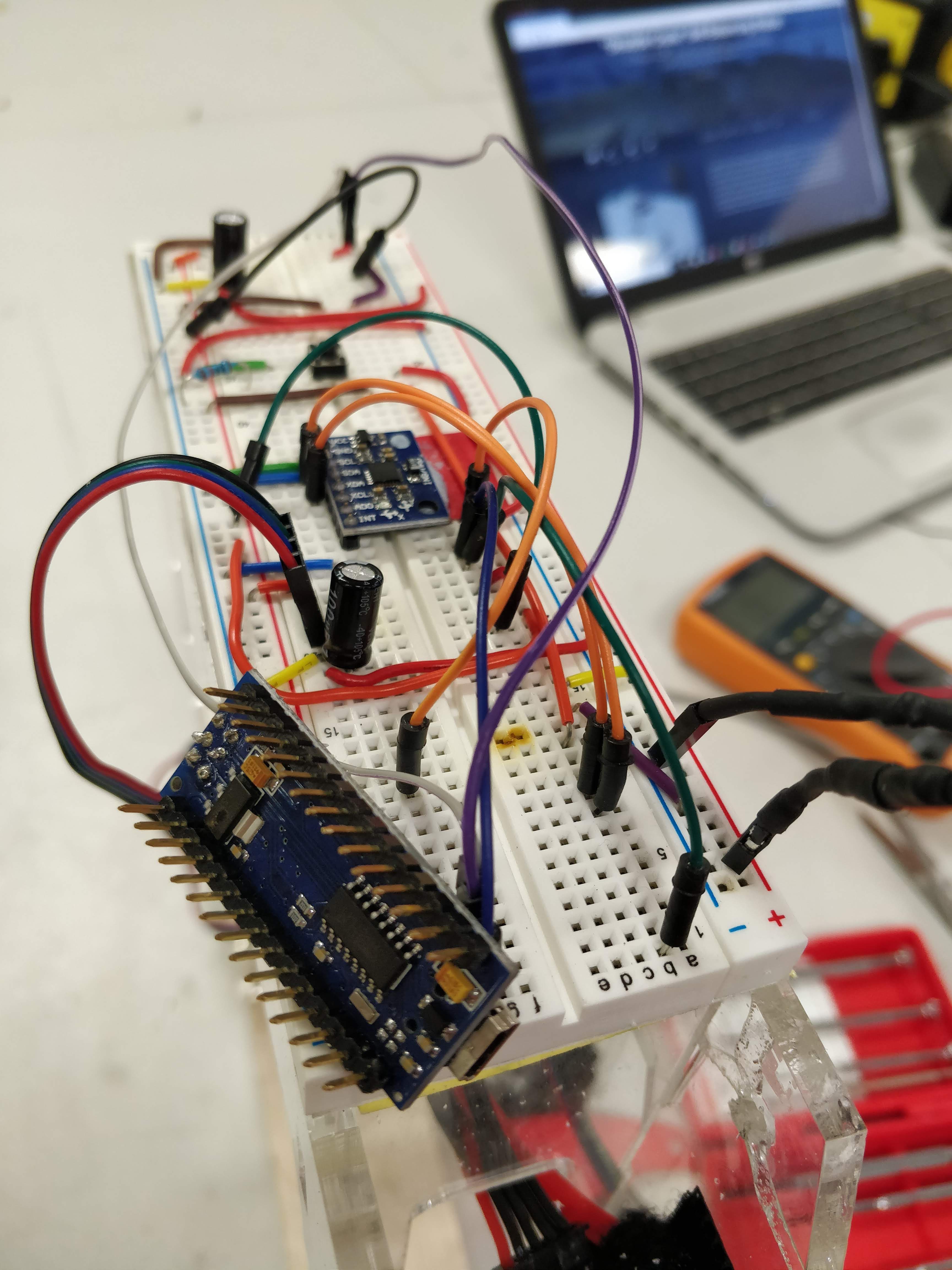
The robot suffered a fall at the start of this week that hindered my progress somewhat. Upon falling over, all components operating directly from the battery voltage got fried; my Arduino Nano clone, and two stepper drivers. Check out the picture below that shows the Nano's burnt out voltage regulator...
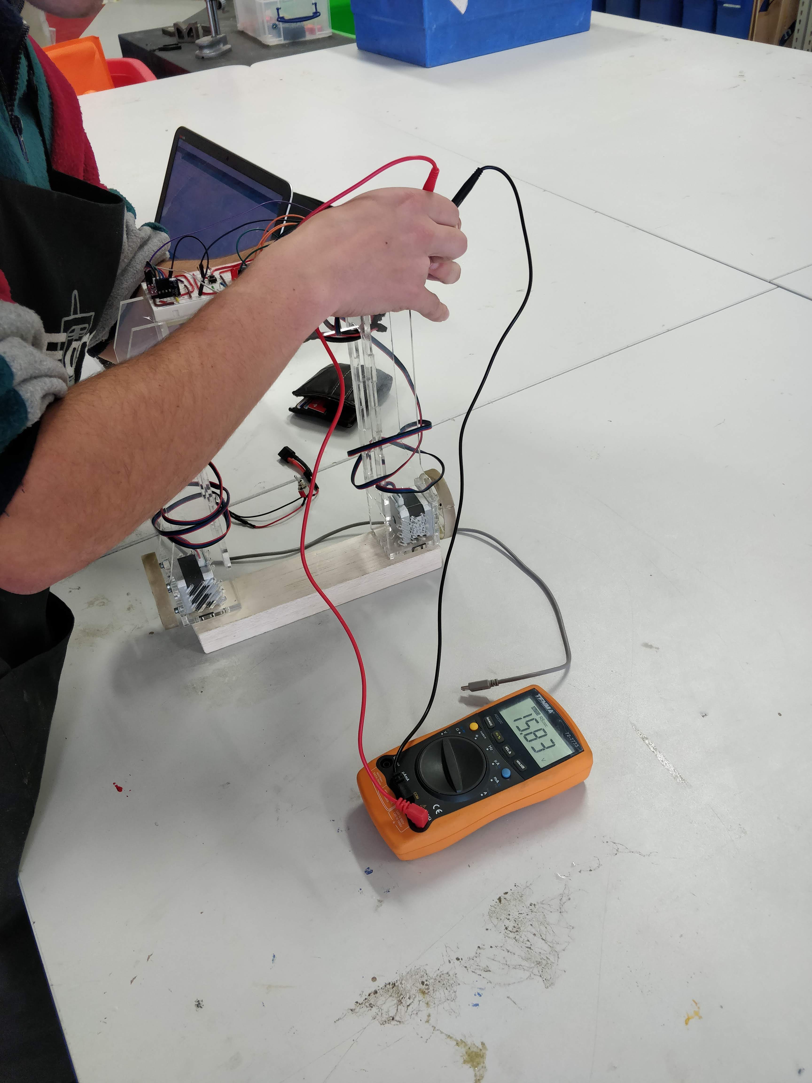
I had to acquire replacement parts which took some time. In the mean time I set about adding the capability of the robot to measure its own battery voltage so that I would be warned if the LiPo battery was dangerously low in remaining charge (I should have done this a while ago). It now gives a warning by turning a red LED on, and its readings were verified using the serial monitor and a voltage meter. You will see the circuit changes and code updates in the near future when I upload the revised code and circuit diagram.
With the replacement of the components and some adjustment of the code, my robot is now fairly successful and I am ready to add a controller and make the robot steer around. Please see the link below for the test that verifies that I am ready to move on to control :)
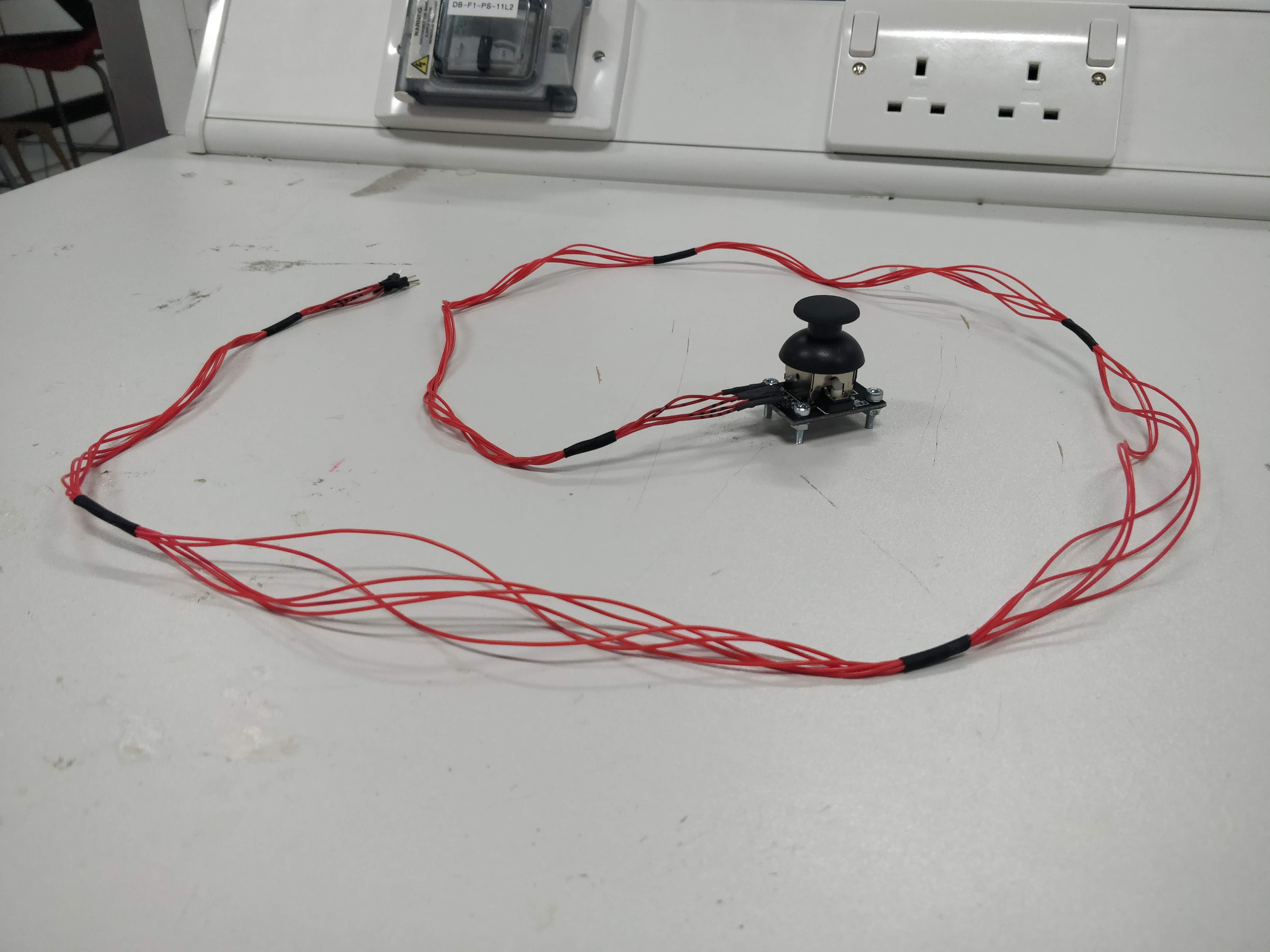
I was going to use a Bluetooth and a custom built android app to control the robot (and still intend to eventually). However, at first I will use a wired joystick module to see if I can just get the robot to responding to inputs (lessening the amount of variables that could cause failure). Today I have started by making long jump wires:
P.s. there is still a drift issue as you can see the robot constantly moving away from its starting position, I am hoping I will still be able to control the robot with reasonable accuracy despite this issue. Any advice here would be very useful (see previous log for more detailed explanation).
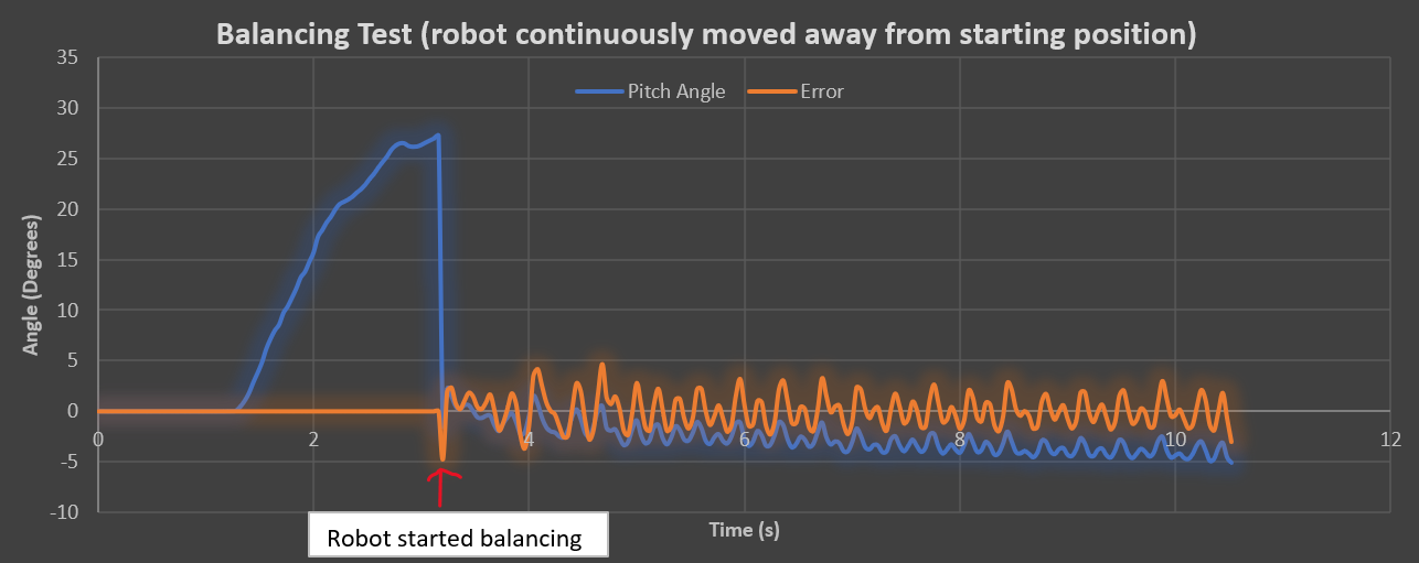
In an attempt to understand the issue of the robot constantly moving away from its start position, data from previous tests was plotted.
This first plot showed that the sensor thought the angle was drifting away from equilibrium; this explained why the robot kept moving in the same direction and the slope downwards explained the acceleration. Next it was decided to see how the PID error value was changing:
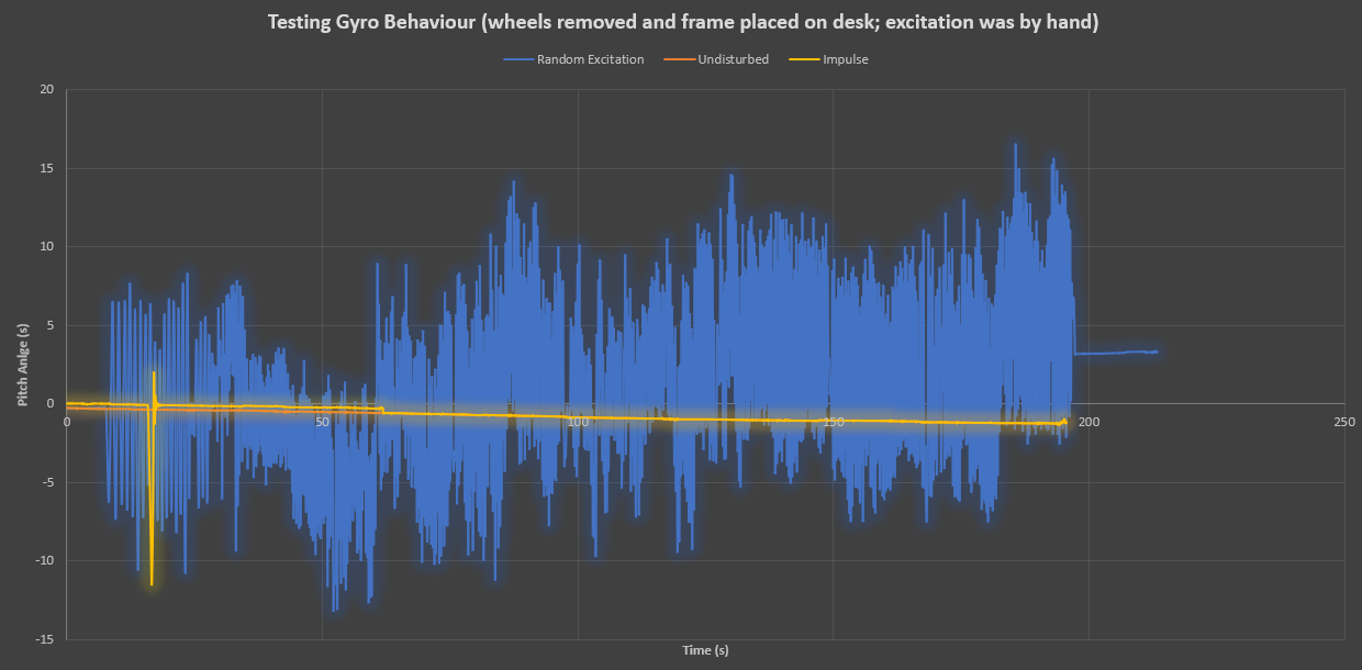
The above plot revealed more evidence for gyro drift. We can see the system error is desired (mean of approx 0) yet the sesnor thinks the angle of the robot is slowly decreasing over time; this is causing movement acceleration away from the starting position to keep itself "balanced". Next it was decided to test the MPU6050 readings outide of a balancing test:
Three tests were conducted each of about 3 minutes duration. 1) sensor was left undisturbed, 2) sensor was given a quick shake then left undistrubed, 3) sensor was randomly disturbed for 3 minutes by hand then placed level again. The results verified the gyro dirft and also showed that the drift is worsened by constant excitation.
Ther current dirft compensation strategy is to determine a set of calibration constants that are determined using an average drift over 500 loops calculated during the robots start up procedure, these constants are then subtracted from the gyros raw values for every program loop. The above results show that this method is not working very well. Two options were considered: 1) calculating the average drift over more loops (1000 loops perhaps) 2) deploying a more intelligent (dynamic) drift compensation technique that could recognise false readings and adapt its influence accordingly.
It would be great to get in touch with someone who has worked with gyro drift in the past.
Following the resolution of the rotating issue, I set about making some changes to the robot:
Replacing the velcro with double sided tape to rigidly fix the breadboard (and accelerometer) to the robot chassis.
Glueing the frame components together (previously just slotted); improving the rigidity of the frame and the wheel axes alignment.
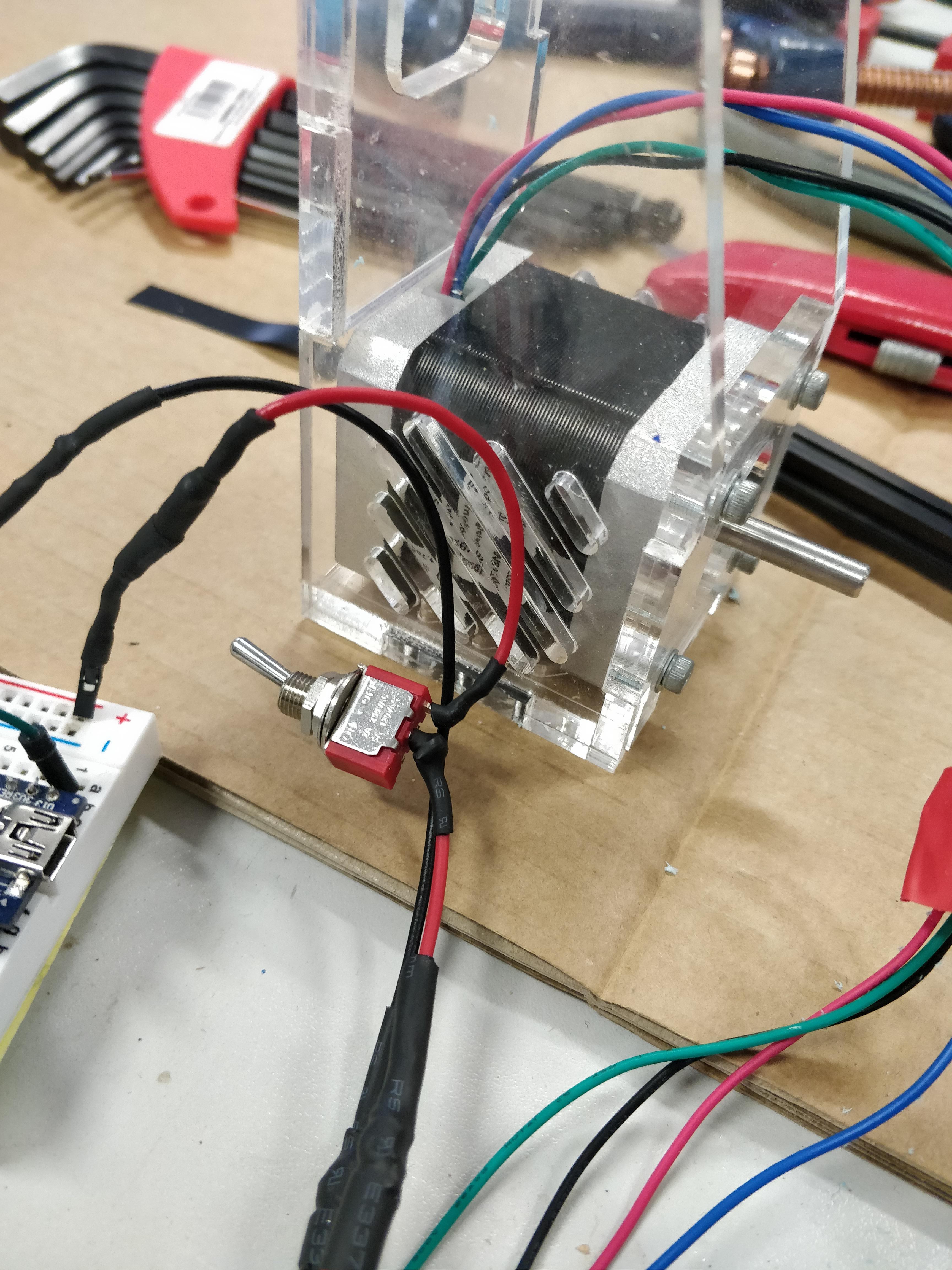
Adding a switch to the circuit to prevent me having to unplug the battery every time.
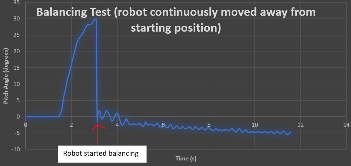
After making these changes I conducted more testing with a friend and saw the following results:
The new calibration procedure worked well and the robot started trying to balance when it was lifted to the equilibrium position; the initial attempt looked very promising, much like the oscillatory behaviour you would expect from a poorly tuned PID controller.
The robot balanced but constantly drifted forwards; routinely travelling about 5m (until we had to stop it due to a lack of space)
The stepper drivers were getting very hot and this seemed to cause the performance of the robot to suffer; missed steps from the stepper motors etc.
With a low value for the Integral gain, the robot performed how you would expect with a badly tuned PID loop. The robot is extremely sensitive to integral gain. Making this a little higher resulted in the robot balancing for longer but always dirfting.
Data was taken during balancing tests to try to discern any control/sensor issues (analysis to follow soon).
In conclusion, the robot still seemed to exhibit behaviour that was not solvable by simple PID tuning. Specifically the drifting and sudden falling in some cases give the impression there are some electronic issues. The drivers getting very hot seems to be a big problem. The next test that will be done is to try using some NEMA 17 stepper motors with a lesser current rating in an attempt to reduce the load on the drivers.
Following the conclusions from Wednesday's testing, I switched out my older stepper drivers for some new higher quality units.
Initially the robot suffered from rotating but that was quickly solved by setting the current higher using the potentiometer.
Once set to maximum current, the rotating issue was solved and resulted in better overall perfromance with no adjustment of PID values (see link below). However, the stepper drivers were getting very hot quickly so testing was only done for short periods of time with cooling breaks inbetween.
The breadboard was velcoed onto the robot frame and filming in slowmotion revelaed that there was some play between the breadboard and the robot that was lilkely to harm the gyro readings (see link below).
The conclusion was to fix the breadboard rigidly to the frame to mitigate these vibrations.
Please see this link for videos of the above testing: VIDEOS
Prior to this testing the robot perfromcance can be summarised: robot could balance for a maximum of about 20 seconds but was very inconsitent, the robot ususally failed because it started to rotate (nothing in the code was telling it to rotate), sometimes the robot would stay at top dead centre then just appear to give up; ie it was not just an issue of a poorly tuned PID controller, there was some undesired behaviour occuring. The code conducted a calibration sequence whilst supporting the robot vertically and would just start trying to balance once the callibration sequence was complete.
Conducted a few hours of testing and adjusting in an attempt to get the robot balancing. I tested in the iForge makerspace using a string harness (to stop the robot falling over) and logging some of the values to the sensor and control values to the serial monitor. Summary follows:
Added code to allow the calibration sequence to run whilst the robot is on its side then when picked up the robot will start balancing if the
accelerometer detects that the robot is upright (see the linked project YARB to understand what I mean). I managed to implement
this but there were problems when the robot actually started balancing
where the robot accelerated very agressively immediately and became
unstable. Investigation through the Serial Monitor revealed that this
new calibration procedure resulted in an inaccurate gyro angle (+4
degrees). For the time being I have disabled these lines of code and
reverted to the start up procedure described above.
Power source was increased from 11.4v to a 15.5v LiPo. This was done in attempt to increase the torque delivered by the motors incase this was the reason for the robot "giving up" (not having the required torque and therefore stalling).
Following the power increase I tried to tune the PID values again to some success. The best balancing time was around 30 seconds but the robot suffered from the same problems of rotating. The motors were definitely delivering more torque so the robot failed less frequently due to "giving up" somewhat confirmed my suspicions of a lack of torque.
A second attempt to prevent the robot "giving up" was setting a limit on the lowest permitted motor speed (other than when at top dead centre) because the robot always seemed to fall when the serial monitor reported a sudden very low motor speed. The effect of adding this meant that the robot consitently failed due to rotation. Thus the rest of the testing was trying to figure out why the robot kept rotating.
When the robot rotated, it seemed that one motor simply stopped driving momentarily. It was observed that this was consitently the same motor failing.
The testing concluded by observing what the rotation was when the stepper motor drivers were swapped. The robot rotated the opposite way and it was deemed that one of the stepper motor drivers was not behaving as desired. The next step will be to replace both drivers with new, higher quality units and hopefully this will solve the rotating problem.
Please see a selection of the testing videos using this link, notably showing the robot rotating then failing.
 Ben Peters