Eric Hertz
-
OBD, oh blah dah
02/25/2019 at 09:11 • 0 commentsUpdate 3-3-19: Probed. See the bottom.
Update 3-2-19 at the bottom.
In another weird coincidence, it would seem my van does not, in fact, use CAN-bus, but in fact uses SAE-J1850 PWM
(ooh, cool copy-paste result! I'mma leave that.)
So, what's the weird coincidence? Friggin' #Floppy-bird.
...Yahknow, with PWM-based data-storage...
Seriously, who's ever heard of a PWM-based UART?!
(hrm, is that kinda what them LED-strings use?).
On [ano]the[r] plus side, this is well within my means to tackle with parts on-hand...
...CAN was looking iffy.
...Had a vague idea of a somewhat-gnarly hack using a regular ol' AVR as a hacked-up SPI-slave via USI, (ala the half-duplex USI implementation of a software-UART, since there's no clock in CAN), a transistor, couple resistors, and some finger-crossing. It'da been near-maxed-out if my OBD port was 1Mb/s CAN, especially with them long packets... but, I'm pretty sure it coulda worked, despite not seeing anything remotely like it 'on the web.
The surprisingly-not-found hack-therein, having been the idea of using a single-pin from the differential pair, with only common/discrete components, for receive-only (ala logging). (screw all them specialized chips!)
...
Anyhow, the idea's a simple logger... converting 41.6Kb/s "PWM" input-data to, say, 115.2Kb/s RS-232 should be easy-enough... (or maybe even USB-CDC, if I'm feeling patient) it's even 0-5V.
Dunno if it's really even necessary to measure the pulse-widths, since otherwise it looks pretty much like a UART; if i can just set the UART's "sample"-timing between 8us and 16us into each 24us bit (like, say halfway through the bit, like most UARTs do), it'll sample 1 or 0, like any ol' UART-data.
I'll leave the rest to linux.
Ooh, a challenge: my dwindling AVR-supply is sans-U[S]ARTs... so bitbanging... I've already written that, but never had reason to go at such high bit-rates. Could be challenging.
Easier, and more-direct, might be to just use an FT2232H, do they allow odd bit-rates? Maybe not as fun.
We'll see if I actually get to it.
Oh, some link[s], sure...
https://learn.sparkfun.com/tutorials/getting-started-with-obd-ii/all
http://pinoutguide.com/CarElectronics/ford_obd_2_pinout.shtml
http://www.obdii.com/connector.html---
Update 3-2-19:
From online-research: Looks like it's not quite like a typical UART byte-frame, so using a typical UART that samples mid-bit won't work. Not becase of the PWM-nature, but because of framing. Rather'n transmitting a start/stop bit with every byte, instead a start/stop indicator is sent once with every 12(?) byte frame.
Little doubt a typical AVR USART *could* be hacked to work, e.g. by setting start/stop-bit-count to zero (is that possible?), and some realtime reconfig. But, again, I'm lacking AVRs with USARTs anyhow. Similar may be doable with USIs (realtime reconfig). But, this, I think definitely rules out using an FT2232. Which is fine by me... or would be, were my devel-setup more like it used to be. Bitbanging has the benefit of being non-reliant on specific hardware, so sometimes it seems more-rewarding to develop in that realm, anyhow. My "Polled UAR/T" code has been quite reliable, and developed/optimized enough as to only add a handful of instruction-cycles in a main() loop. Modifying that for this new protocol might result in some trickle-down improvements.
Alternatively, and probably more-relevant to now, I could develop this alongside #Floppy-bird 's pwm-nibbles. Again, both projects would benefit each other. Which is kinda nice.
Though, they do differ enough as to bring into question whether they should use the same code-structure. Chiefly: PWM-nibbles are >2-valued (ideally 16-valued!), and *fast*. This'll require quite a bit of optimization (maybe even assembly-programming), and also will almost certainly rely on system hardware/peripherals, e.g. timer-input-capture. Further, The pwm-nibbles will be coming in a continuous stream, and basically need to be handled *immediately* upon reception. With the rates we're talking about, the instruction-count overhead of a data-buffer, or even an interrupt, is a lot to ask. More-likely the data-handling will have to happen in the same code as the data-reception. Which, frankly, is part of the point of #Floppy-bird ... realistically it'd be *better*-implemented with discrete logic... a few gates between the floppy-drive's /Read-Data pin and the LCD... The point, there, was that the floppy drive, its built-in timing, etc. is driving the timing, data, etc. for the LCD. The uC, then, is really only in the picture during the writing phase. I wanna throw a pwm-nibble floppy-disk at a floppy-drive wired to an LCD and a tiny bit of logic, and have essentially a digital picture-frame with 160 images.
The uC for read-back is really only in the picture due to parts-on-hand, and [maybe] because it's a little faster to prototype.
So, realistically, despite the outward-appearance of being *very* similar, the OBD pwm-data reception/handling software is likely to be quite a bit different... quite a bit more like a bitbanged UART.
That-said, there are striking similarities between the two. Remember the "sync" pwm-nibbles? Those are basically the same as the frame-start indicator in J-whatever-PWM... and, later pwm-nibbling thoughts involving packets, ala rewritable sectors on each floppy-track, one per LCD row (160 sectors per track!), again very similar to J-...-PWM's packets.
So, who knows, maybe after some more mulling-over I'll decide they can use a common codebase, or even merely reuse some snippets... (but, am still not convinced of the use of timer-input-capture for J...-PWM...)
There's also some consideration that my OBD-port may not really report *anything* other than error-codes for code-readers, and maybe only when-requested... I plugged in my multimeter and detected no AC while idling, revving, etc. That doesn't mean much... I should dig out the logic probe. But it wouldn't not make sense. As far as I'm aware, there's only one computer in my van's system, and none of the sensors I've encountered communicate serially. (They send analog. I'm glad for that... they're diagnosable with simple always-on-hand tools!) So, there's really no need for realtime communication going on on my OBD bus... It may be more like an interactive session: a "dumb-terminal" of sorts, when attached, may be sitting at a prompt awaiting a user-request (like typing in 'dmesg'). Or it may be more like stderr, where that same dumb-terminal, when attached, would constantly be displaying messages in realtime. Dunno. But, I don't think, in my system's case, it's like tapping into an ethernet hub and watching all the traffic.
(FYI, half the fun is figuring this stuff out, I'm not asking for answers. If I wanted the silver-platter, I'd just buy a friggin' OBD scanner).
Oh, also, be careful looking up resources on the matter, J...-PWM and J...-VPW are not the same...
https://www.cnblogs.com/shangdawei/p/3235907.html
----
3-3-19
Working on a more-important van-issue, came across my logic-probe... Not at all where I remembered. Glad I hadn't dug around for it!
Anyhow, now the OBD-signals have been probed.
Previously, I measured the positive data signal (it's differential!) "B+" with my multimeter in both DC and AC modes. DC I got ~12V, AC.... ones-of-millivolts. Didn't seem like data to me.
Today, noticed that I'd been measuring between +12V (rather'n Common) and B+.
In fact, there's a Chasis-GND, and a Signal GND.
So this time, the logic-probe powered by 12V+ and Signal-GND, and probing B+ in CMOS mode, what appears to be a signal. Mostly-low, but pulsing-high.
This, though, too, is a hokey test. The signals are allegedly close to TTL-values. Well, except for one resource, which claims roughly TTL for Vil-max and Vih-min, but up to 20V for Vih.
So, before I ran the probing, I just wanted to check... my probe is switchable between TTL and CMOS... CMOS (4000-series), as I recall, can handle up to 18V. But, that doesn't necessarily mean the probe is designed for that... E.G. 74HC00-series (also CMOS), as I recall, is rated to 7V. And, frankly, I've seen a *lot* of circuitry in my life, and >5V is *very* rarely used. Note that the switch-setting, as I understand, allows it to indicate high or low *only* for *valid* voltage-levels. Inbetween/Hi-Z doesn't get indicated. This requires more-sophisticated input-circuitry than a 7400 or 4000-series chip, which'd still give an [undefined] output even for "invalid" input.
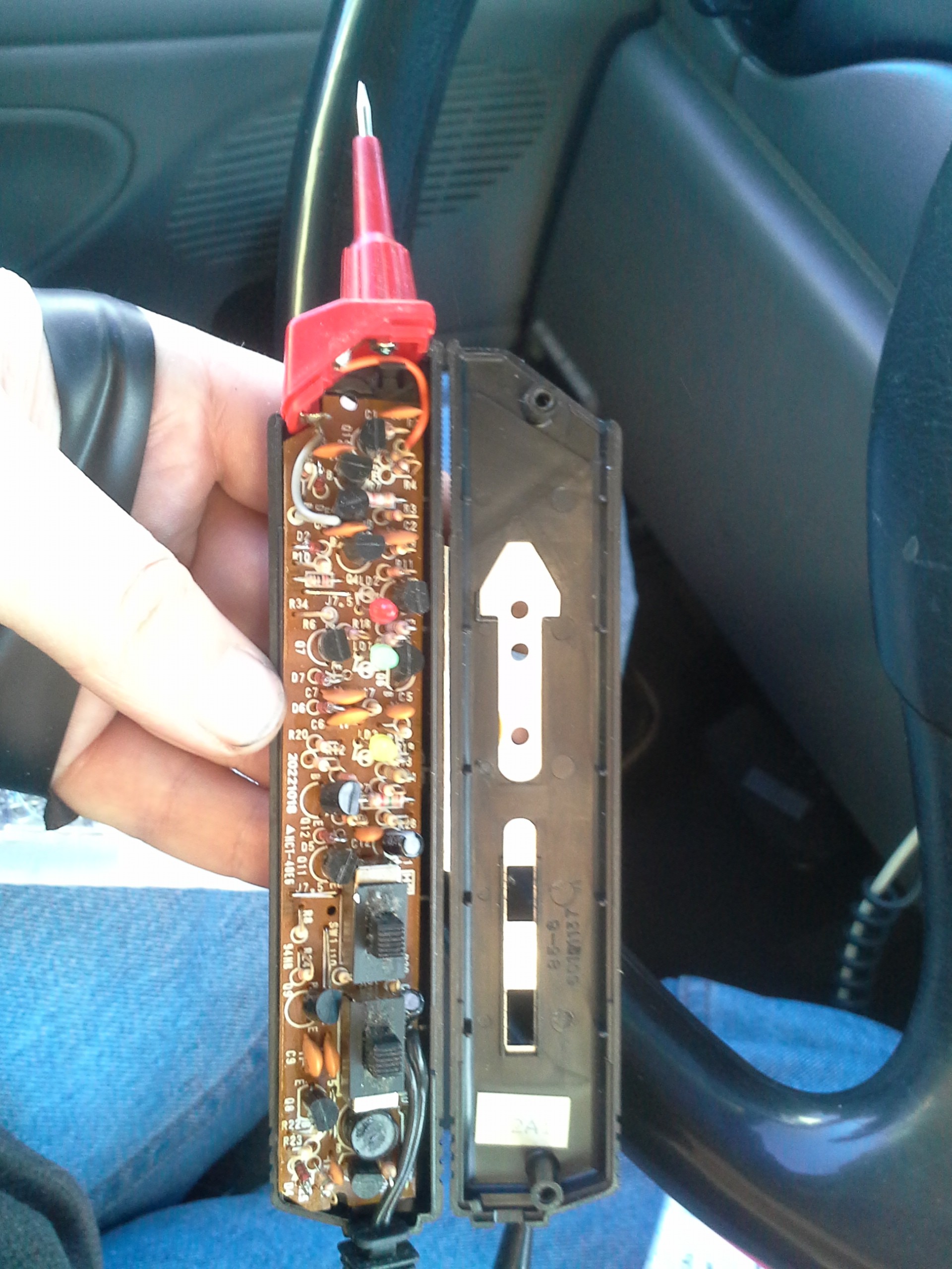
Opened 'er up to find the entire circuit is made of discrete (through-hole!) transistors. Interesting. And *numerous*. Doesn't *exactly* answer the question of whether it's safe to run off 12V, but transistors are pretty resiliant, right?
![]()
So, the hokey-factor: Again, most resources claim ~TTL-level signals, and I'm running the probe in CMOS-mode running off 12V. At 12V, valid CMOS levels would be probably something like Vil-max=4V, Vih-min=8V. So, if we're getting 5V on the signal line, it shouldn't read as "high,"
Hokey-test.
(Note to self, a handy logic-probe add-on would be a 5V regulator. Another would be actual indication for invalid and out-of-range input)
Regardless, it showed highs and mostly-lows. And it seemed the highs were coming in periodic bursts... And B- seemed exactly opposite, mostly-high... so that seems like data.
Also, re-probed with the multimeter. B- ~4.6VDC, ~0.8VAC. B+ ~0.4VDC, ~0.6VAC. Can't quite make that out... but square-waves + [non?]RMS makes for weird AC measurements. Those are, however, definite AC measurements, indicating a bit of variance on those signal lines. Far more than just "ripple." Plausible reconfirmation of data. And, 4.6DC+0.4DC=5VDC... makes sense for differential signals varying between 0V-5V and 5V-0V, no?
But, no explanation why I saw nada data-like when measuring between +12V insteada GND, before.
Anyhow, something to go on.
I think a transistor between B+ and my 5V uC might be wise, just in case 12V goes on that line... Or maybe just a 10k series-resistor allowing the input diodes to clamp.
And, if my resources are realistic, for read-back, only, I probably don't have to look at both sides of the differential signal.
Weee, working with poorly-documented signals without a 'scope!
-
Applied Physics Question
01/18/2019 at 20:18 • 0 commentsImagine a system. wherein a controllable amount of fuel turns a shaft. Two gear-settings can be chosen, ideally for the least fuel-consumption, based on a varying load.
Is there some sort of crossover-point where, for a specific load, the two gear-settings require the same amount of fuel to result in the same speed at the load?
-
hackacharge!
12/19/2018 at 12:57 • 0 commentsok, guess I left the dome-light on too long...
Starter cuts-out before it turns-over (long-story, let's just say some moron. [or greedo?] designed a system with a relay with too high a release-voltage).
Gotta get some more juice in that batt.
Have a jump-pack... Because of the relay, you're supposed to charge for a bit, rather'n jump... but either way, apparently that didn't have enough juice, either.
Third-option (skipped over the obvious one...): House-batt... Obviously, jumper-cables from house-batt to starter-batt.... Yeah, didn't think of that.
OTOH: house-batt is jury-rigged to charge (slowly) from main system through cigarette-lighter and a series resistor... And... it was plugged-in. So, house-batt-voltage probably equalled main-batt voltage. So, really probably doesn't matter that I somehow completely overlooked the obvious jumper-cabling in favor of:
Jump-pack has a 120V charge-input... to charge the jump-pack. House-batt has a 125W 120V inverter.
Yes, it *almost* sounds like a free energy scheme.
Yep. Then, the brilliant idea that rather'n wanting to charge the jump-pack, what I really want to do is charge the main batt... Now, I'm almost certain jump-packs aren't usually designed for this... but mine didn't complain, and the inverter never once turned on its cooling-fan... so, it's obviously not charging anywhere near 125W... right? (well, it is quite cold out, and in, that was the whole point of starting the engine... anyhow...)
So, about then, halfway in, I realize the jumper-cable possibility, then think of @Ted Yapo's attempts jump-starting a car from a coin-cell.
The key, here, is that the house-batt voltage could be [drained to] quite a bit lower than we need on the main battery to start. We Have A Boost Converter, maybe a bit like joule-thieving?
So, that combined with concern I'd blown a fuse in the jump-pack-charger, which might explain the inverter's silence, had me looking for ways to measure whether it was charging... yahknow, without having to move from my balled-up-trying-to-stay-warm position on my chair.
First stupid attempt: I built-in a jumper for that! Measuring charge-current to the house-batt. Zero. Shit, the fuse is blown. No, wait, the inverter draws 0.6A unloaded, and it's light is on... OH, Right... charge-current *to* the house-batt.
Now I'm debating unhooking yhe jump-pack from the main-batt to throw my meter between... but it's cold out there.
And then the obvious, again a bit late, but not too [late]: Reach all of 2ft and measure the friggin' voltage from the lighter-outlet, see if it's increasing.
Holy Snap... it hasn't even been an hour (Maybe half) and it's already reading 12.7V, 12.7, 12.8! Mind-you, we're charging two batteries, one of which is *significantly* larger than the charger was [likely] designed-for. And doing-so *in-system.* This is incredible!
So, on to testing The Ted Theory: House-batt is a steady 12.03V. YEAH! Joule-thievery! er something.
Disconnect... yep, 12.6, 12.5, 12.4... but pretty slow, surprisingly. And house-batt's like 12.1, now...
So, definitely charging. Friggin' awesome.
A few more minutes and give er a go... again lazy (mind you, it's 3:30AM at this point) and chilly, try to figure out how to remove the charger... I already put it through the wringer, starting with it connected would be cruel. But not cruel enough to step outside. What to do? Oh, huh... charger didn't have a switch... It's either plugged-in or not. And lo and behold there's a switch on the ol' inverter.
Crank it over... and here we are, now cozy-warm and lazy, still "topping off" three batteries--main, the jump-pack, and house-batt--from my alternator,
Man, this level of "lazy" might be borderline risky to these systems. I wouldn't recommend it. OTOH a well-designed multipurpose jump-pack with inbuilt-charger would be wisely-designed to handle AC charging of a car's main-batt. Nevermind fast pack-recharging from the cables. Guess I'm just used to low-quality stuff.
Sometimes things go alright!
(but, seriously, if my main batt had more than 12.03V on it, which it must've to have charged the house-batt to the level where it, *after recharging* the main-batt, still had 12.03V on it, there is ZERO justification for that relay's kicking-out. And, further, risking a $50 fee and mandatory servicing in so-doing! Nevermind being potentially dangerous!)