-
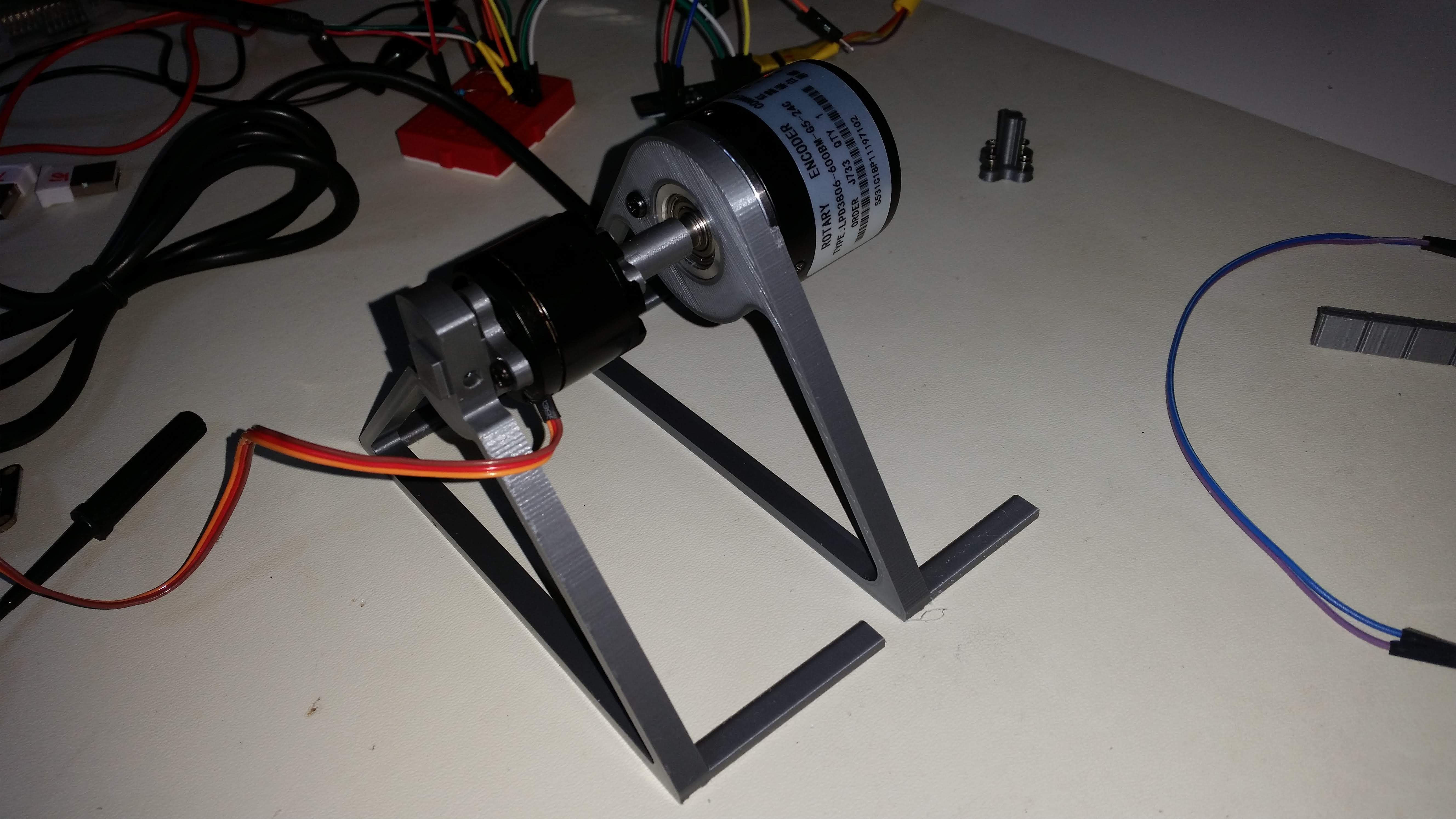
Encoder for the bldc test bench
01/04/2019 at 21:15 • 0 commentsRotary encoder 600 steps

nRF52 Firmware
After the failure to use the qdec peripheral, fallback was on pio, interrupt, but that gives another advantage, the one of capturing timestamp on the nRF for every event, so that the log to the pc does not induce any speed signal distortion.
This is how the mqtt messages look like
jNodes/75/text {"ts": "597185480", "A": "1432", "B": "1428", "H": "1660"}
jNodes/75/text {"ts": "597191402", "A": "1432", "B": "1429", "H": "1661"}
jNodes/75/text {"ts": "597399004", "A": "1432", "B": "1430", "H": "1662"}
jNodes/75/text {"ts": "597406683", "A": "1431", "B": "1430", "H": "1661"}
jNodes/75/text {"ts": "597417026", "A": "1430", "B": "1429", "H": "1659"}
jNodes/75/text {"ts": "597424182", "A": "1429", "B": "1428", "H": "1657"}
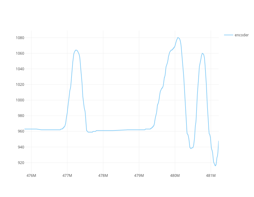
Timesamped view of the motor position (angle step)
- Note that the firmware does not always report at the highest sampling rate, rather report on change, with a minimal cycle, then when no changes, keep a slow (1 sec) alive signal to show the user on the live graph that the position did not change.
- It is nice to see the data path, from the microcontroller that logs in rf, serial python to MQTT, then an MQTT browser client link it to plotly that can export the data to be shared on an iframe and embedded right here !
- actually iframes are filtered out from hackaday, so simply a screenshot and the interactive plot is availabe through the link : interactive plot

-
BLDC Static torque Test bench
01/03/2019 at 11:37 • 0 commentsObjective
- Identify the BLDC motor static torque
- simply put : How many grams can it hold how far ?
PC Gui repo : https://github.com/HomeSmartMesh/raspi
firmware repo : https://github.com/nRFMesh/nRF52_Mesh/tree/master/applications/nrf52832_rovarm
Run the web app and the python serial to mqtt gateway
start python py_rf_serial/cli.py
start live-server web_plot
Web gui :
Monitor MQTT messages
pi@rfserv:~ $ sub 'jNodes/75/#' -t 'Nodes/75/#' -v | tsMotor under test
Torque measure

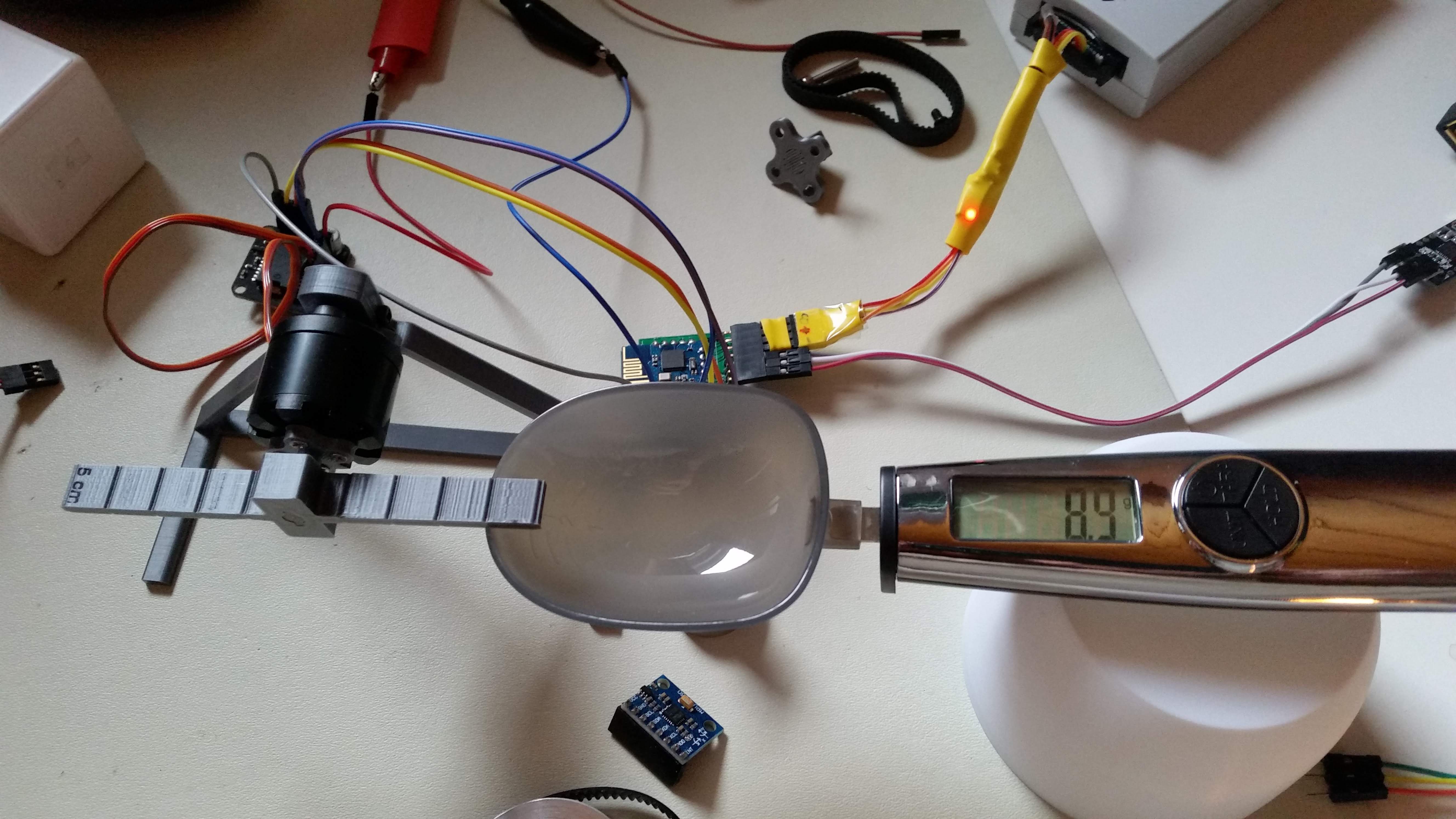
The photo was taken without pressure on the motor, so the 8.9 grams pointed out are not relevant, see results for measures summary
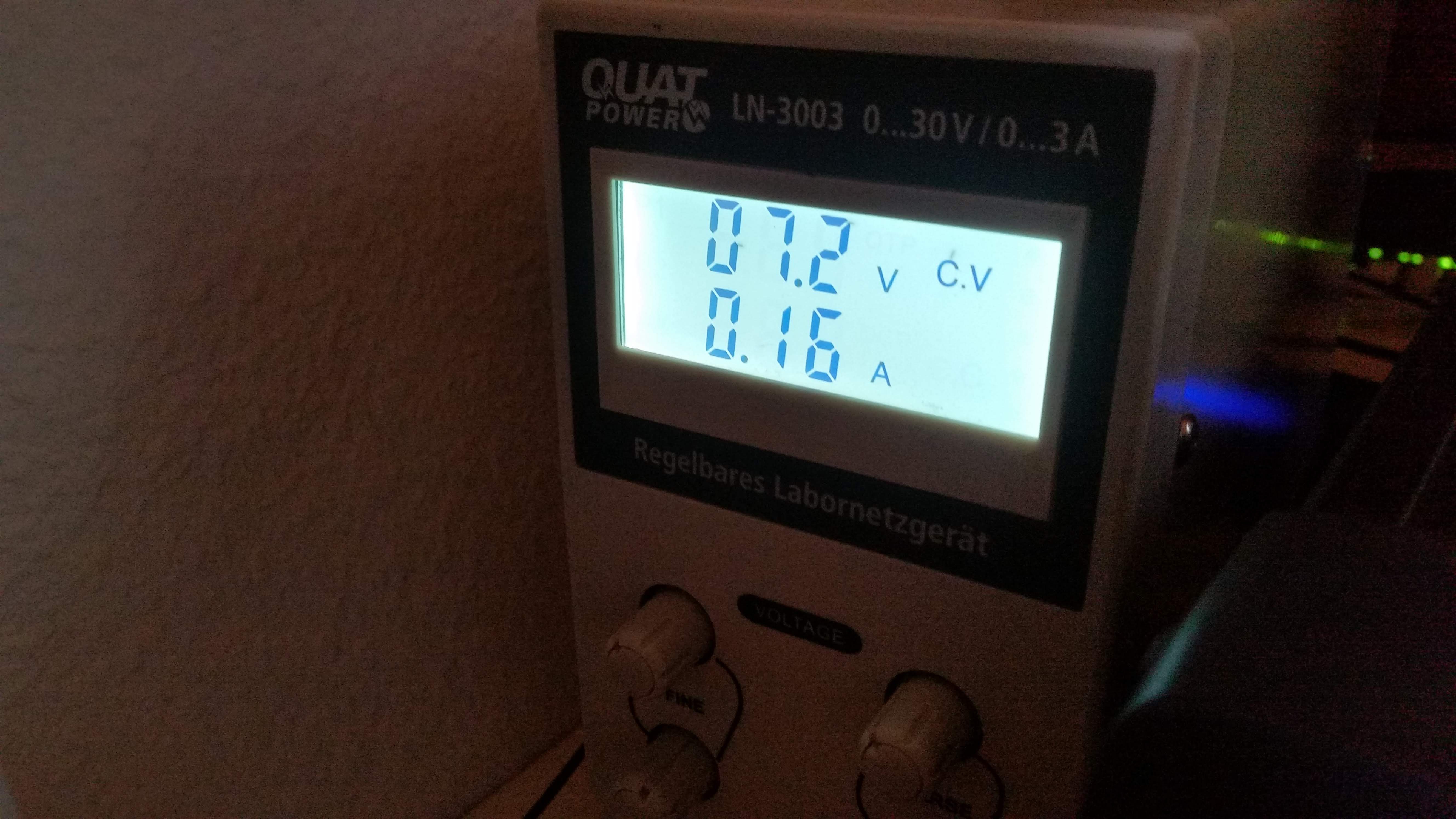
Power

a current limit is set and when the measure is performed, it is simply checked if the current limit is reached by checking if the voltage drops or not.
Results
only direct pio permanent enable is shown, the pwm sine control is excluded for the moment
ESC Coil 4 cm measure 1 cm conversion Nm 7.2 V 3.8 V 310 mA 75 g 300 g.cm 0.029 Conclusions
- It's important to make sure the voltage measure is at the motor coil not at the power supply or ESC input.
- The torque measures are descent for such motor size, still quite disappointing when it comes to direct motor drive expectations.
- The pwm sine flow control does not provide the highest possible torque, which was to be expected. In the pwm sine control, when one coil pwm is at its maximum, the other two do have partial triggering as well, which is counter productive when it comes to maintain the motor holding its step.
- a simple set of one enable pin (one coil) to high voltage, provided a higher torque and higher current consumption
TODO
- use a different angle function for the pwm values generation that is not sinus rather one that gives full throttle to one channel by having both others at zero in some angles.
Open points
- How to define what is the maximum possible voltage/current to be applied without burning out the motor ? The wire thickness is 0.15 mm, and expected usage in static permanent conditions.
Self standing balancing robot
nRF52 mesh of motion sensors, Gazebo for physics simulation, BLDC motors simulation and control, CAD with Fusion 360. Fully Open source.
 Wassim