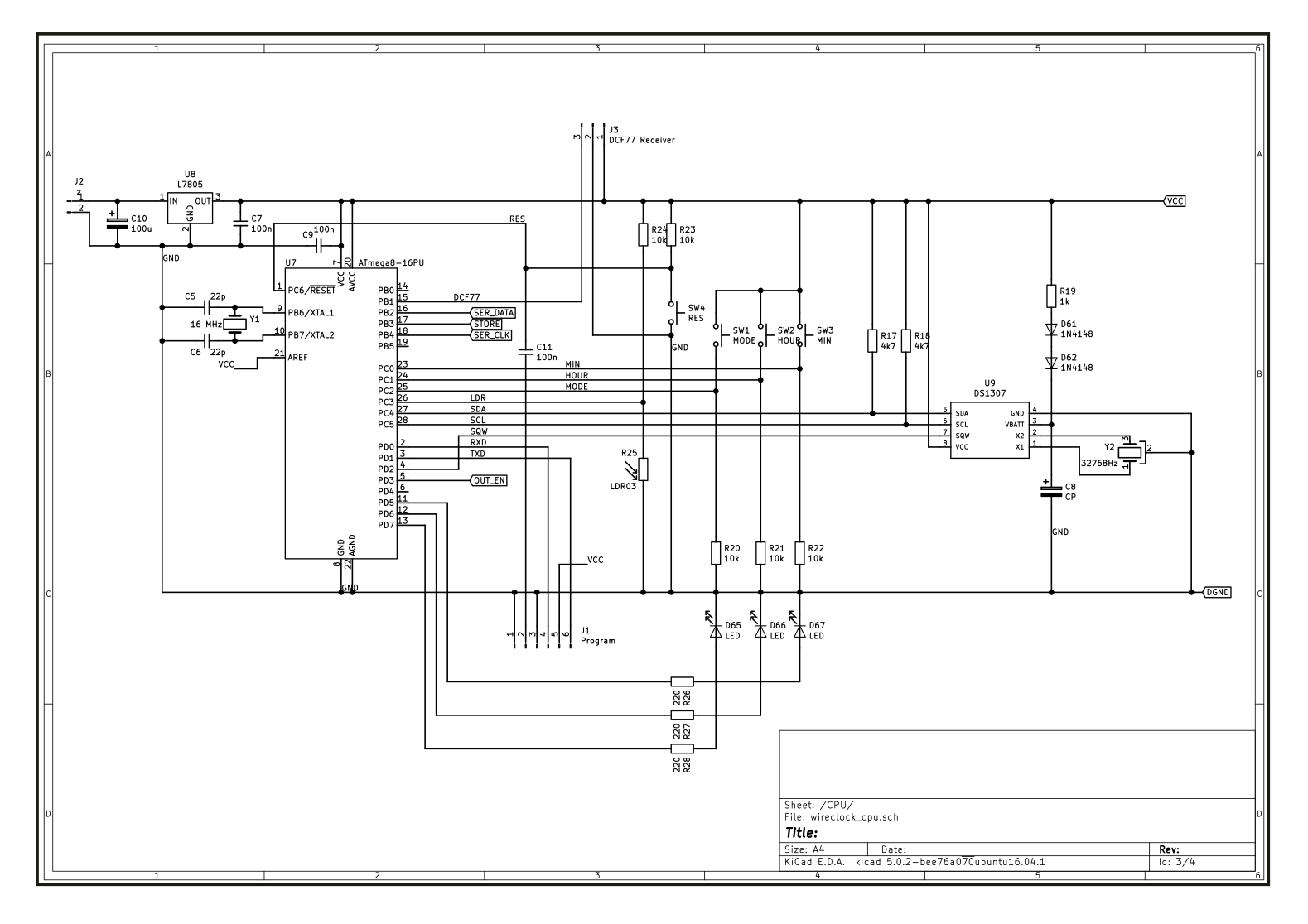
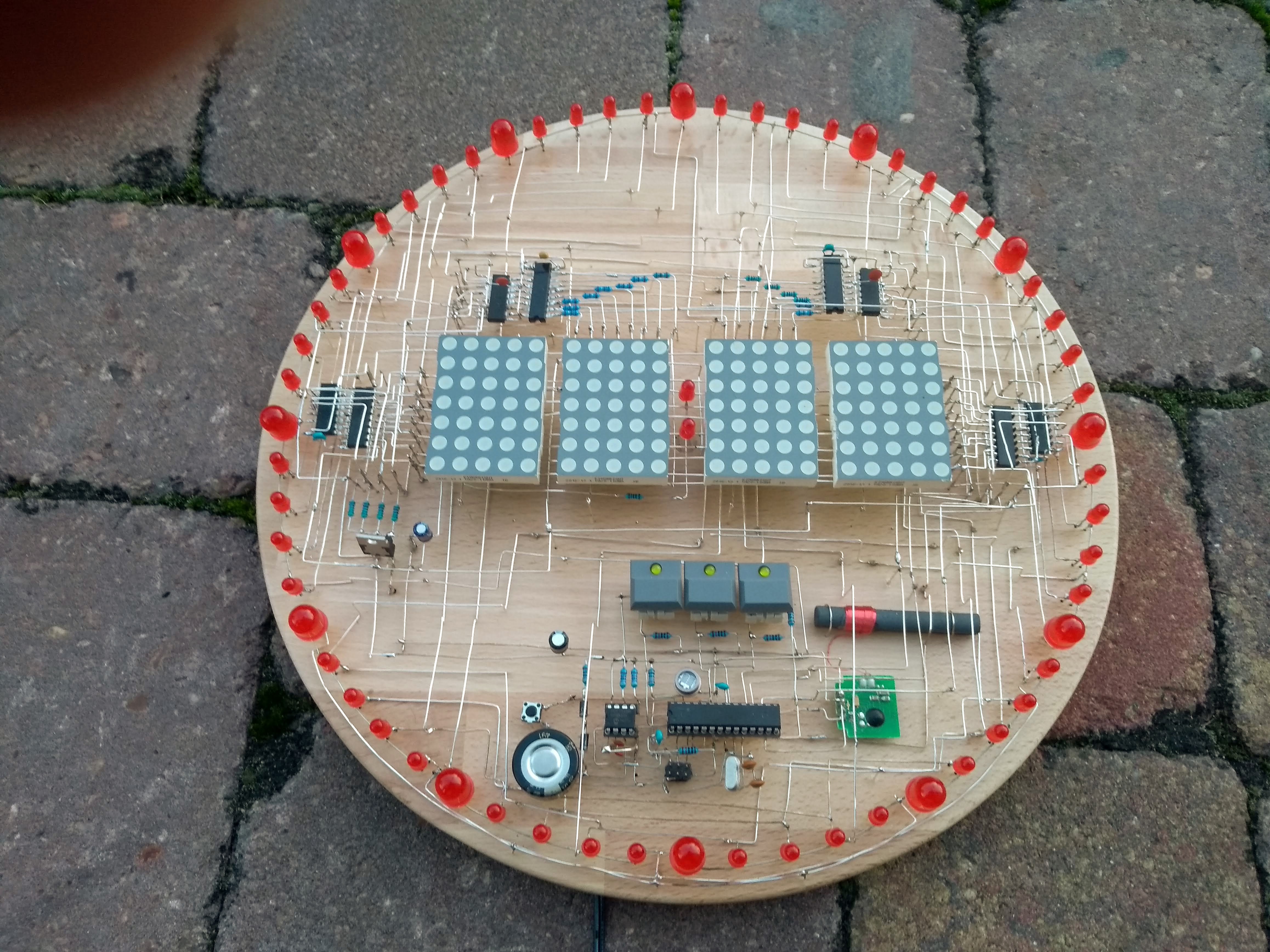
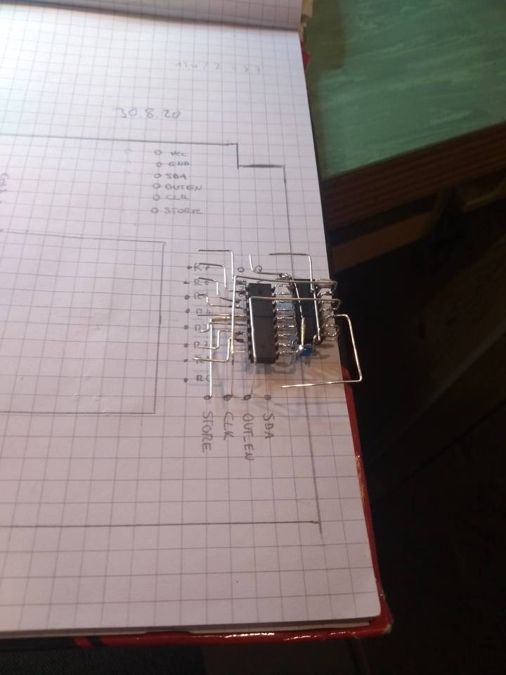
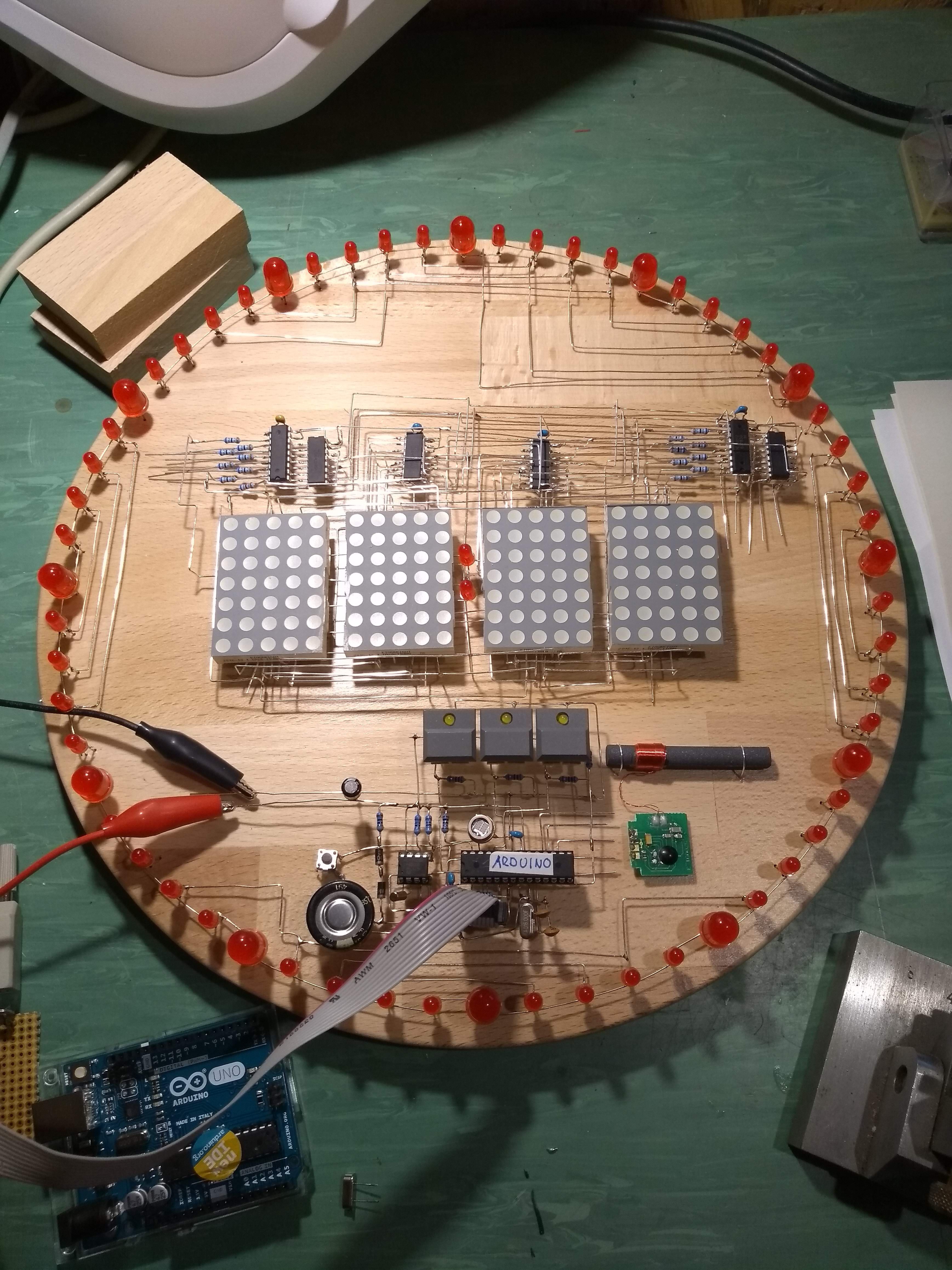
The CPU is an Atmega 8 with Arduino boot loader to make programming easy. Connected to it are an RTC chip and shift registers for controlling the LED matrix. A purchased DCF77 (German atomic clock, sending on 77 kHz) time receiver module is connected via J1. J3 is used to program the board.
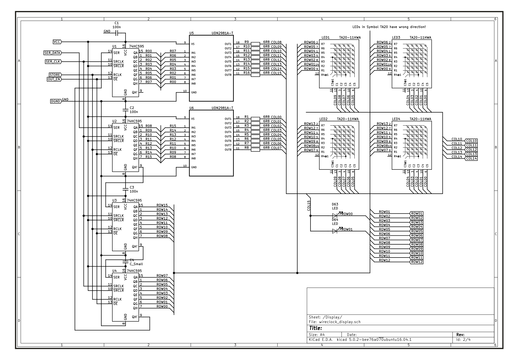
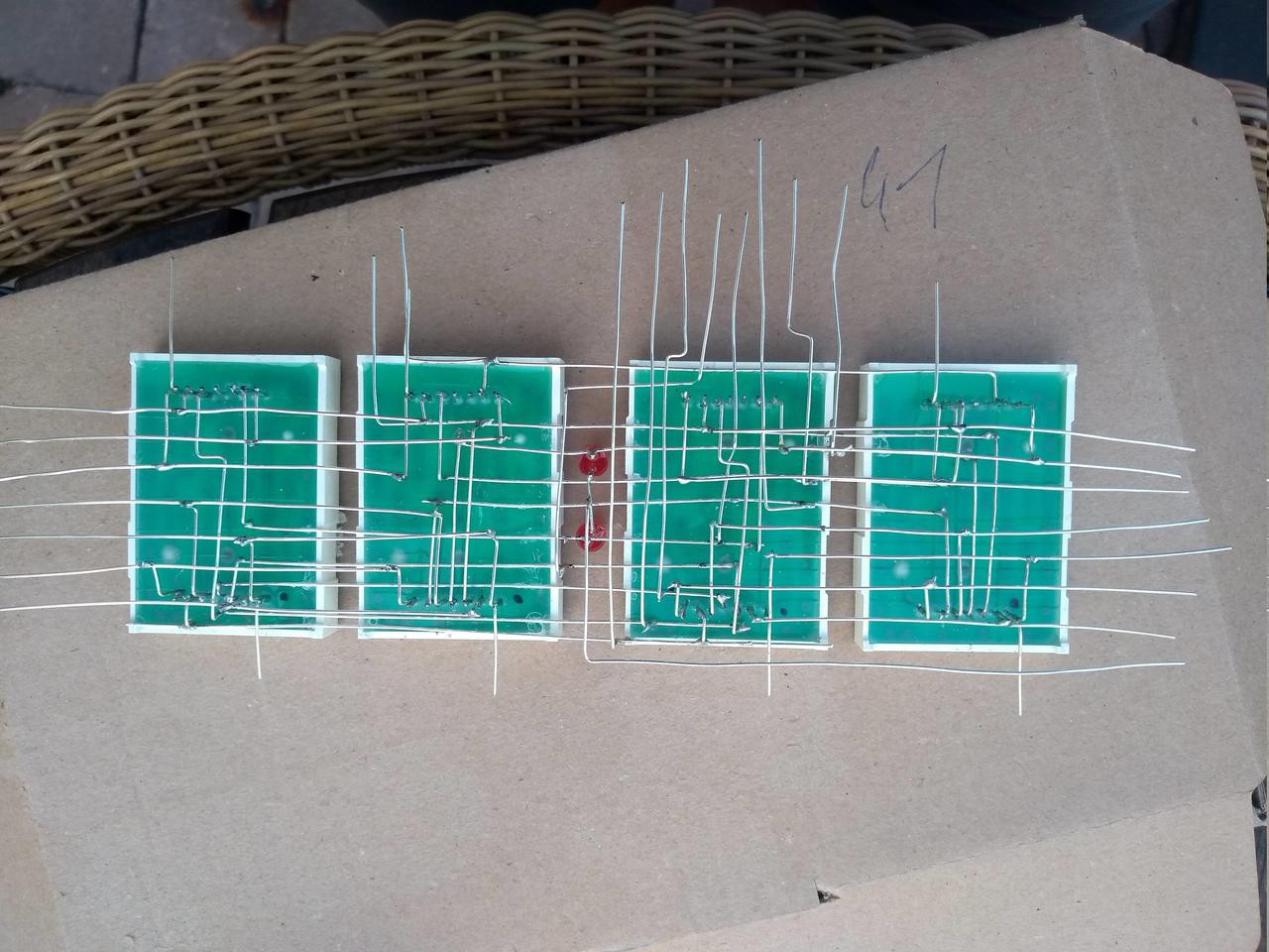
4 dot matrix displays with 5x7 pixel resolution are used to display the time. These are controlled via the above-mentioned shift registers U1 ... U4. To increase the output current, the signals for the columns of the matrix are amplified with drivers.
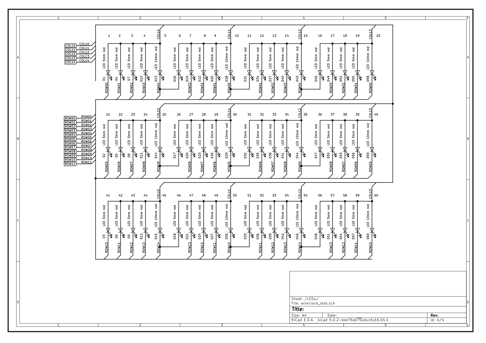
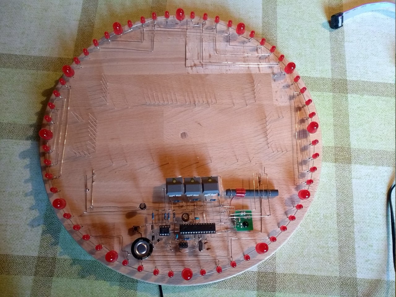
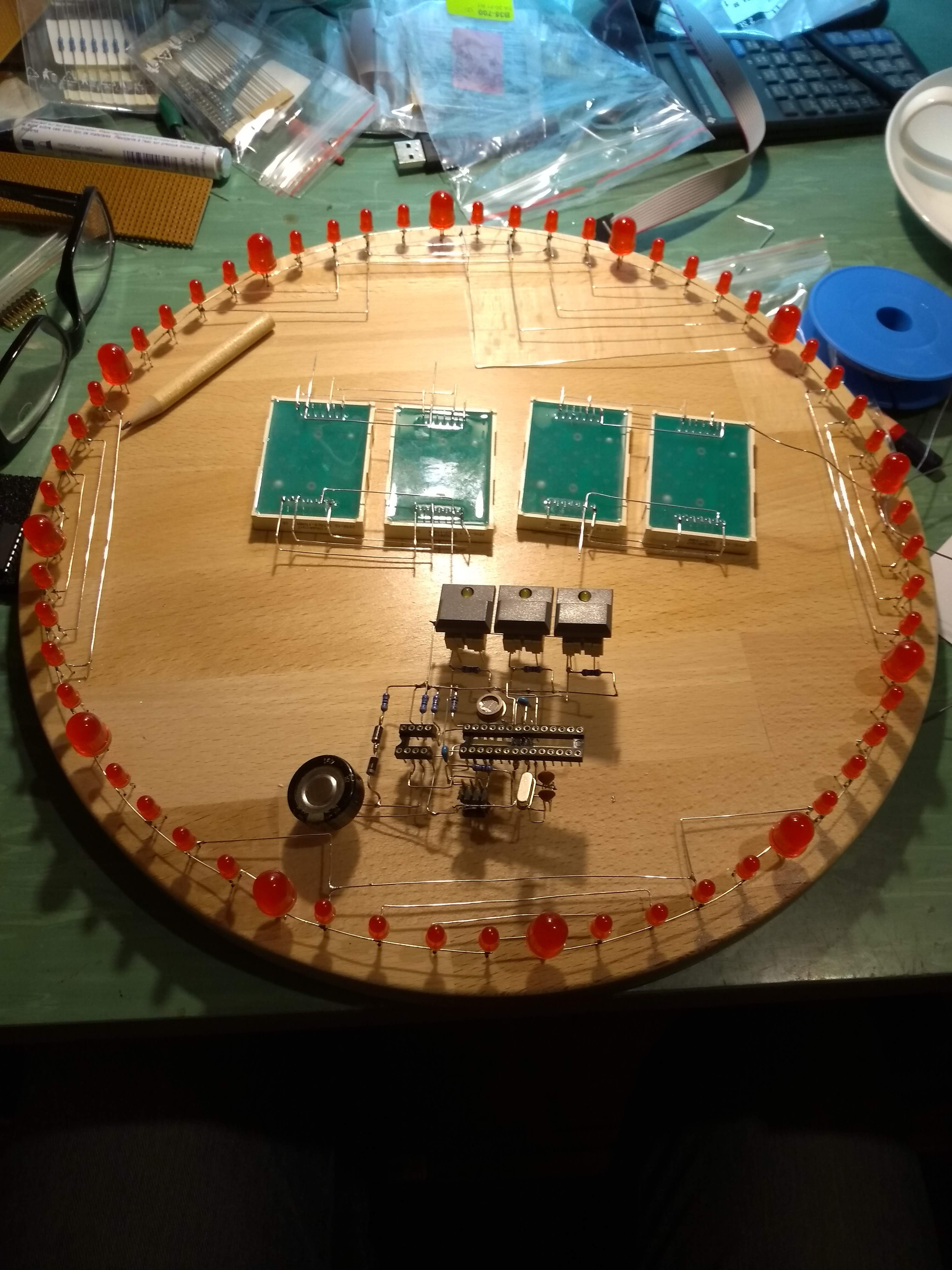
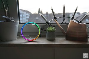
To make the whole structure look more like a clock and to have a bit more "action" on the display, a ring of LEDs is mounted on the outer edge, which will display the seconds. One LED is provided for every second.
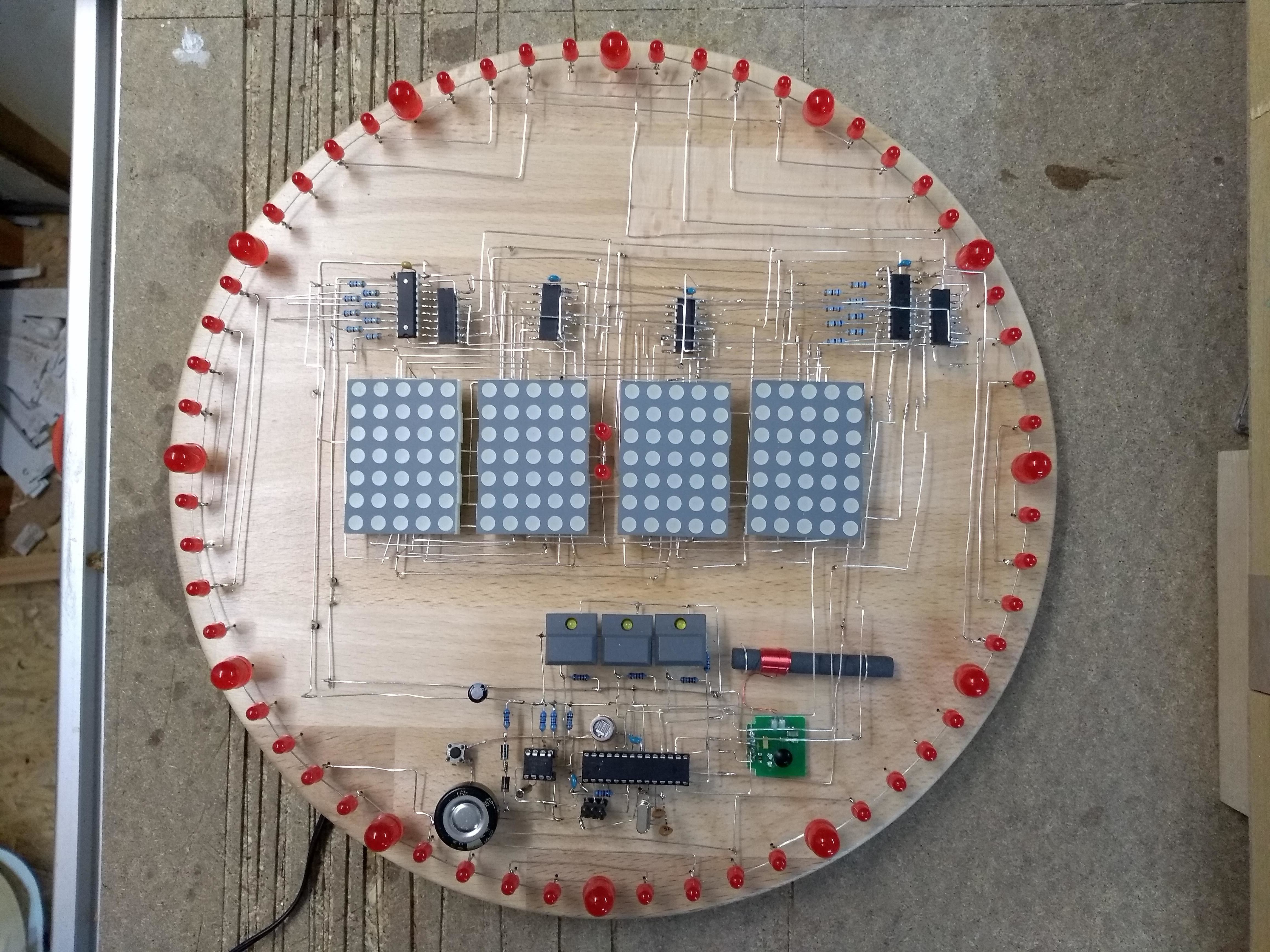
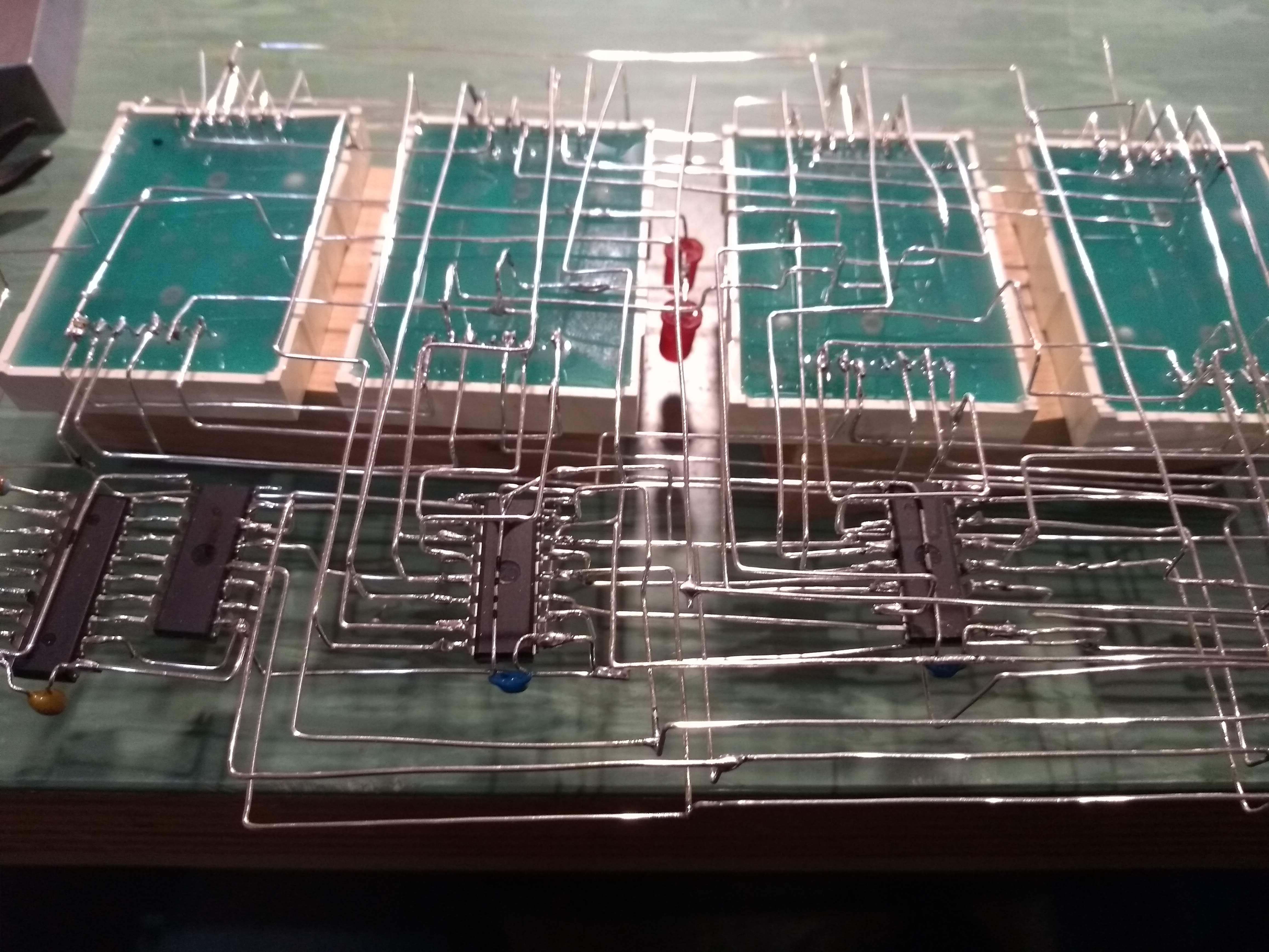
 The soldering work is still ongoing...
I managed to setup the communication between PC and the ATMEL (which took way too long this time...) The displays are connected, but there is a wiring fault I haven't found so far.
 In the meantime I found out that I burnt 2 of the 74HC595 Shift-Registers....
I'm sad about it because I found some shorts and don*t know how to fix all the bugs.

 Fabian
 David Christianson
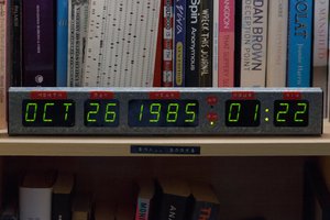
 Stephen Holdaway
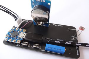
 Mark Wilson
Thank you for the advice but I'm not sure if I'm able to finish it in that time...