-
Wohoo! It works!
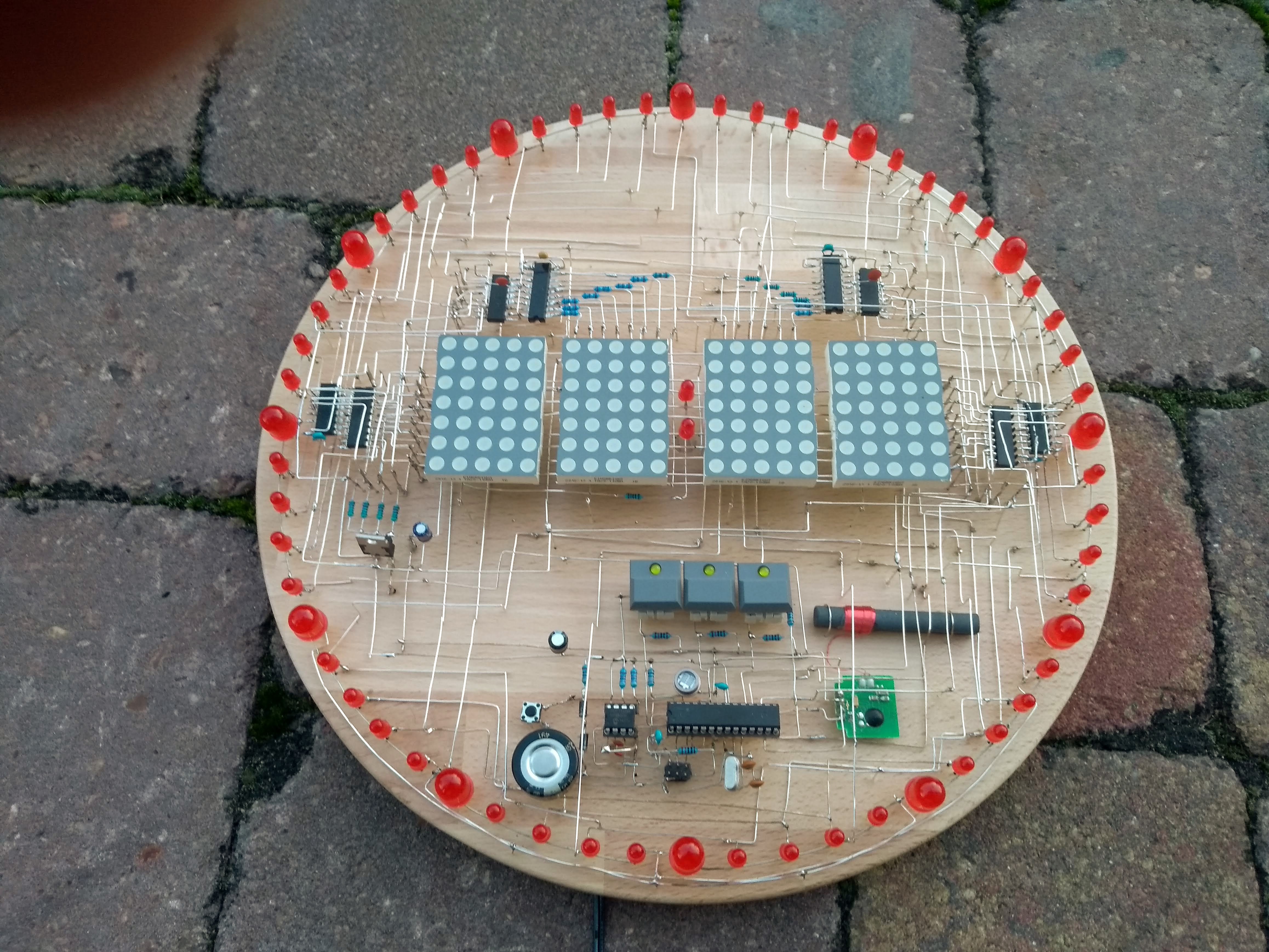
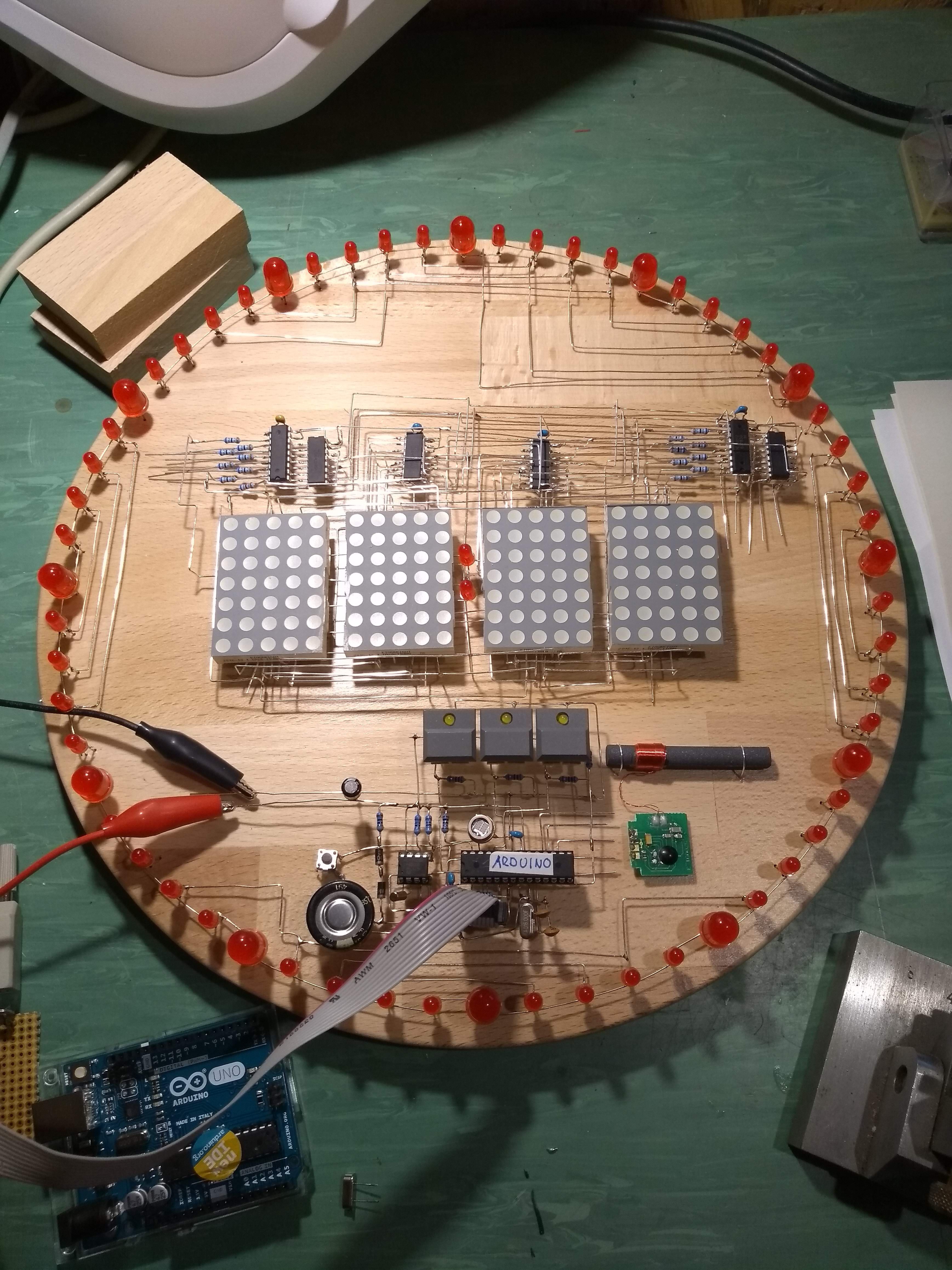
11/28/2020 at 17:25 • 0 commentsAfter intensive testing of the components (and fixing some shortcuts and other bugs) I finally soldered everything together. I was a bit nervous before powering it on, but... it works! I wrote a test program and was able to switch each LED on and off separately.
I found out that the dot matrix display is not bright enough at 5V because of the multiplexing rate of 1:16. I increased the supply voltage for the LED supply to 9V to have enough brightness.
To make this possible I had to add additional buffer ICs. Driving the rows directly with the 74595 shift registers does not work for supply voltages > 5V.
The LEDs to display the seconds are a LOT brighter compared to the display modules. To dim the 60 LEDs I had to increase the appropriate row driving resistors quite a bit.![]()
I like the look of the assembly, it is more or less like I imagined it. Mechanically it is sturdy enough. This was another lesson I learnt building this beast. I added a lot of upright wires that I glued in holes drilled in the base plate. Those upright wires serve as soldering points for horizontal wires.
The more of those "poles" I added, the better got the overall mechanical stability.
The next step is to complete the software and a video of the clock in action.
-
2nd Try...
11/26/2020 at 17:29 • 0 commentsThe first attempt of bringing this to life was a fail. I toasted some chips and had a lot of shortcuts between the unisolated wires. I could not find a way to find all the errors in this mess of wires. Therefore this project had to sit on my shelf fore quite a while... :-)
But after more than a year I was in the right mood and decided to give it a second try.
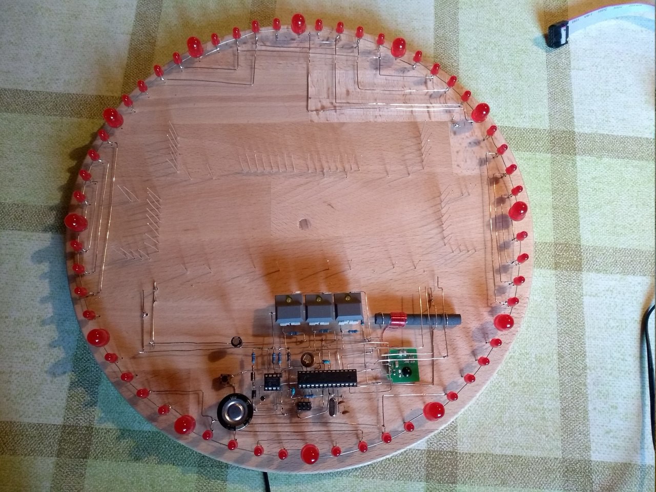
The circuit around the Atmega was working, It was possible was to communicate and upload software. I removed most of the other stuff and started the wiring (nearly) from scratch.
![]()
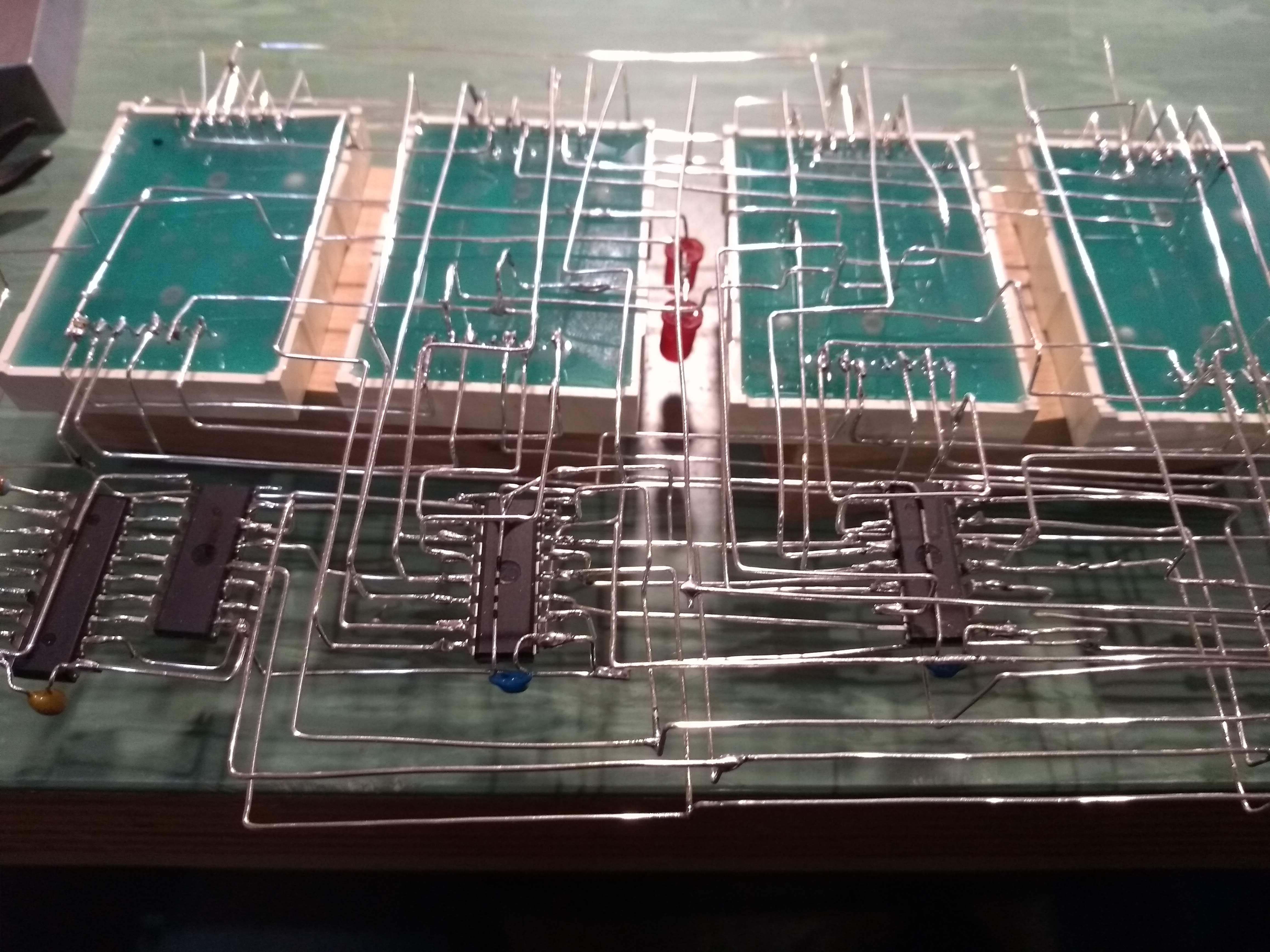
This time I did a lot more planning before starting the rewiring. I tried to divide the circuit in several modules and assembled the modules separately. After the assembly of each module I tested it thoroughly for short circuits and any other wiring errors.
![]()
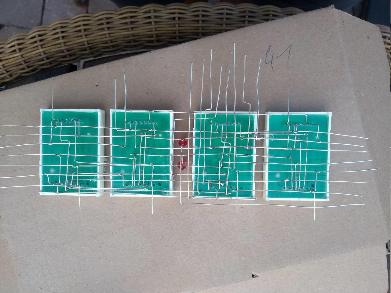
This is the display module with rows and columns (not completely ready). The rows and column wires connect to the "poles" in the picture above. It is rather easy to test a sub module of this size and correct the unavoidable errors.
![]()
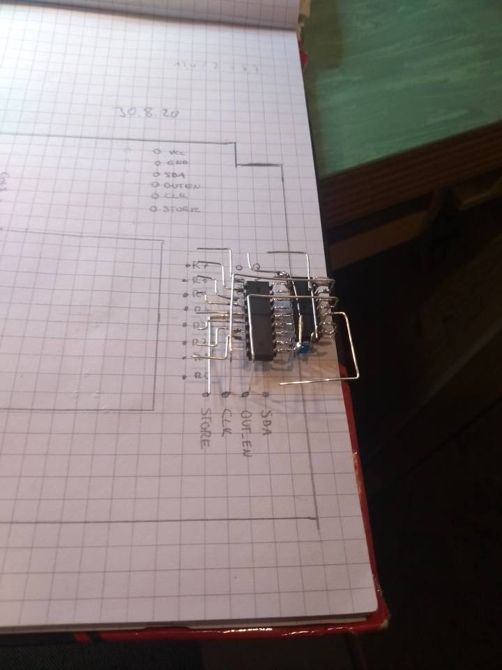
One of the row drivers...
-
Mechanical construction
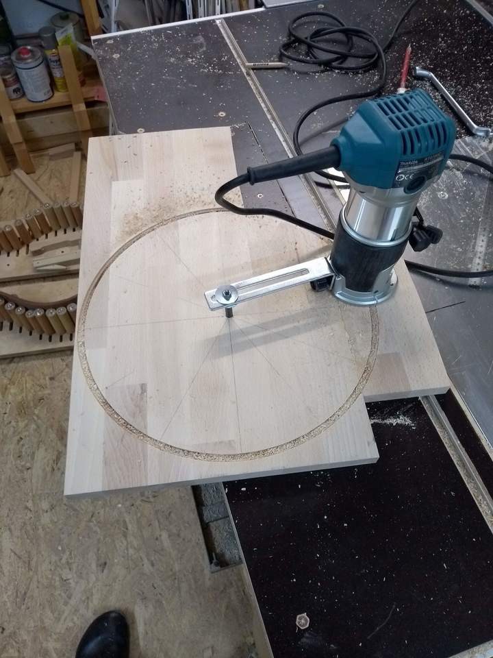
01/03/2019 at 23:31 • 0 commentsI glued the base plate together from scraps and then brought it into a circular shape with the router.
![]()
At the edge I drilled two rows of holes into which the LEDs for the seconds display are inserted later.
![]()
When wiring I try to use only right angles for optical reasons. The circuit is wired with 0.6mm silver plated copper wire.
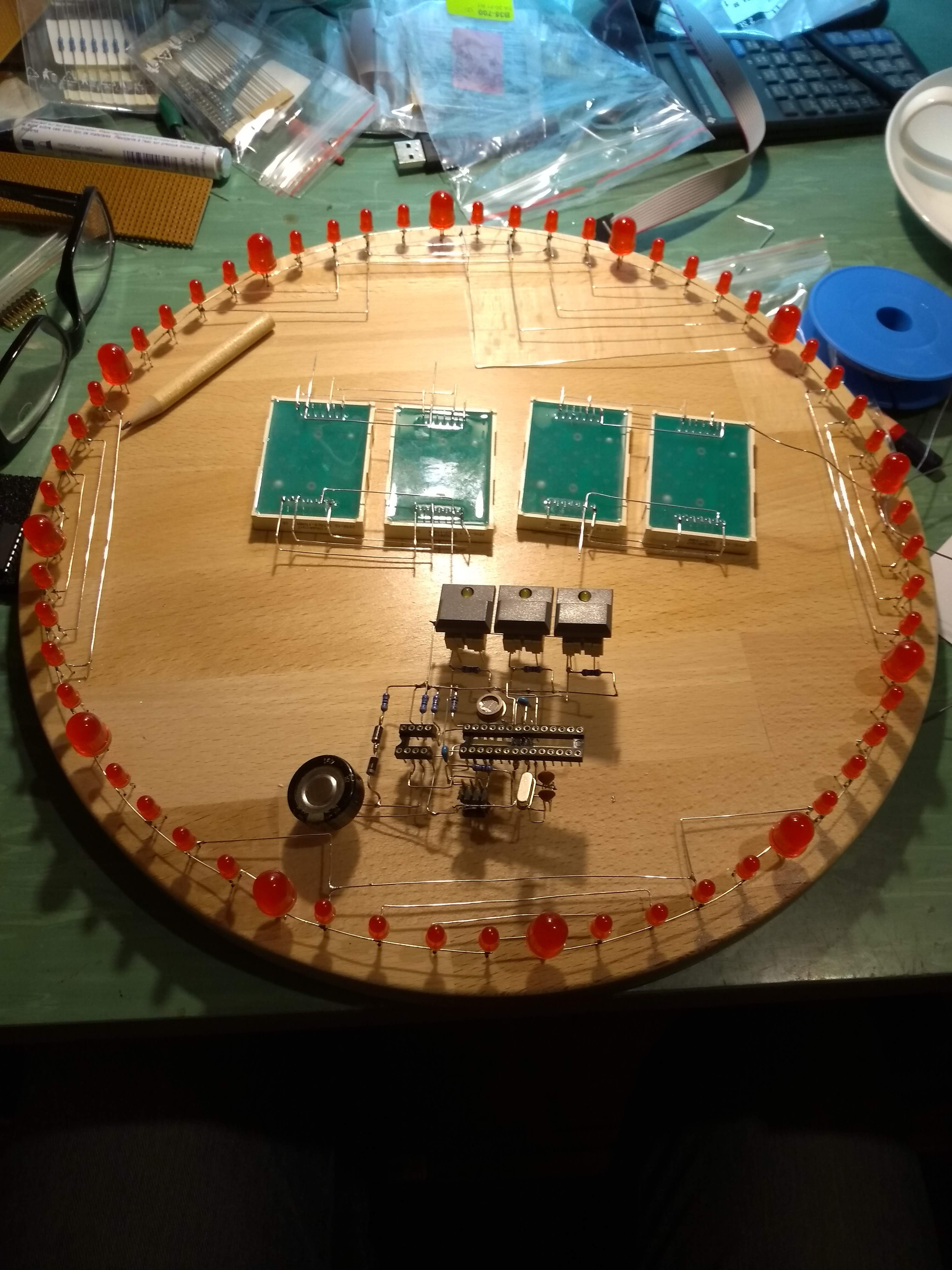
The wiring is a real challenge ... as you can guess on the following picture. I built three main components separately : CPU, display with shift registers and LED ring.Before the display wiring will be mounted on the board, I double checked the wiring again and found some bugs.
![]()
The mechanical construction is nearly done. There are still missing connections in the LED ring and the connections between the 3 components. But after building up the display I'm not worried about it.![]()
At the moment I'm trying to upload the software. This seems more difficult than expected. But I keep on trying... :-)
WireQlock
An electronic wall clock whose circuit interior is visible as a flying structure without a circuit board.