 Laser Developer
-
1Unruly glossary: TLAs (Three Letter Acronyms)
- LiDAR = Light Detection And Ranging - a sensor that measures distance using laser light.
- TOF = Time Of Flight - measuring distance by timing how long it takes a flash of light to reach a target surface.
- PLD = Pulsed Laser Diode - a semiconductor chip that produces bright flashes of laser light.
- APD = Avalanche Photo Diode - an optical detector with high sensitivity.
- TDC = Time to Digital Converter - an IC that uses digital codes to represent short time periods.
- SMPS = Switch Mode Power Supply - a circuit that changes voltage levels by switching current through an inductor.
- TIA = TransImpedance Amplifier - an IC that converts current from a photosensor into a voltage.
- IBM4 = ItsyBitsy M4 Express - a microcontroller breakout board manufactured by Adafruit Industries.
- PWM = Pulse Width Modulation - a method of changing the duty cycle of a digital signal to produce different analog voltages.
- SNR = Signal to Noise Ratio - an indication of how big a signal is compared to unwanted noise.
- VGA = Variable Gain Amplifier - an amplifier with a digital interface to select the gain.
-
2Unruly overview: How does it work?
![]()
The Unruly LiDAR is made up of electronic circuits, optical parts and software. None of these are trivial even though they may look simple at first glance.
The electronic circuits are on two circuit boards that plug together. The first board is the ItsyBitsy M4 Express controller and this is the brains of the LiDAR. The other board carries all the LiDAR specific components including the optics.
The electronic circuits on the LiDAR board perform a number of functions. The measuring sequence starts when the TDC (time-to-digital converter) receives a start signal from the processor. At the same time the laser driver circuit fires a PLD (pulsed laser diode) to produce the outgoing flash of laser light.
The return signal is detected by an APD and amplified in two stages. Firstly, a TIA (transimpedance amplifier) converts the current from the APD into a differential voltage. Secondly, a VGA (variable gain amplifier) increases the amplitude of the signal to a useable level.
The analog signal is then converted into a digital signal using a comparator and this digital signal stops the TDC. The results from the TDC are transmitted back to the processor via an SPI bus.
-
3Unruly optics: Seeing a long way...
The optical components give the Unruly LiDAR its performance. Many thanks to Tracy for the hundreds of hours that she put into designing these critical parts.
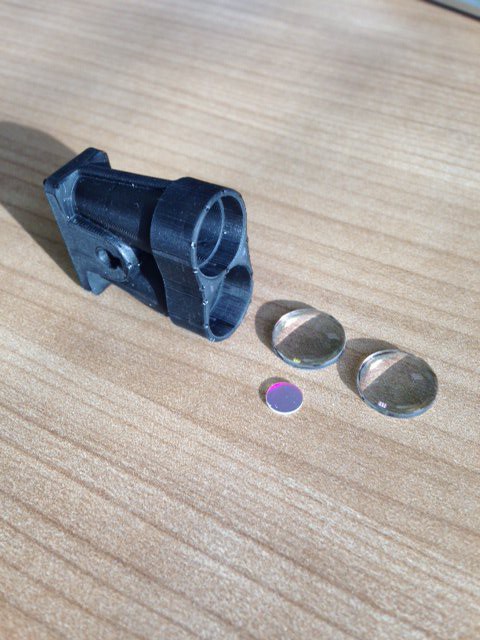
The PLD (pulsed laser diode) produces short flashes of light forming a beam that spreads out over a wide area. Without additional optical components the beam loses intensity and the measuring range is reduced. To correct for this beam divergence the Unruly has a lens placed in front of the laser, making the beam come out nearly parallel. This optical collimation significantly increases the measuring range.
Photons in the outgoing laser beam hit the target surface and scatter in all directions. Only a small proportion of these photons head straight back, most of them are lost. In order to collect the returning photons a focussing lens is placed in front of the optical detector. The lens collects more photons than the detector could do on its own so the measuring range is again extended.
Mixed in with the returning photons are additional photons from various sources of background light such as the sun. These unwanted photons create noise in the detector making it hard to pick out the laser photons. To reduce this noise a narrowband optical filter is placed directly in front of the detector. This filter allows light through that is the exact color of the outgoing laser light and blocks light from other sources, letting the Unruly work even in bright sunlight.
The detector is a very sensitive APD (avalanche photodiode) that converts the returning photons into electrons. The APD is 100 times more sensitive than a regular photodiode and it produces many electrons for each photon that it detects. This sensitivity helps the Unruly pick up very weak signals from distant target surfaces.
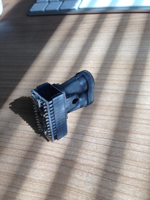
A precision 3D printed holder keeps all the optical parts in place. The optical alignment is critical to the Unruly performance and errors as small as 0.1 mm can reduce the measuring range significantly. Tracy used a resin printer with an industrial grade, black resin to make the holder.
![]()
-
4Unruly connections: Plug me in!
![]()
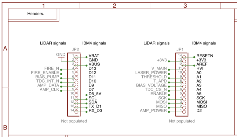
The Unruly LiDAR connects to the ItsyBitsy M4 Express through two headers along the edges of the boards. The schematic gives the labels for both the IBM4 controller board and the LiDAR board. In the software the LiDAR labels are used in the main code and the IBM4 labels are used during hardware initialization.
The last five pins on JP2 are available for serial and I2C communications and ports D5 and D4 (along the short edge of the IBM4) are available as servo drivers. There is one more spare port on D3 (also on the short edge of the IBM4) for use as general purpose I/O.
-
5Firing the Unruly laser: Gently with a big hammer.
![]()
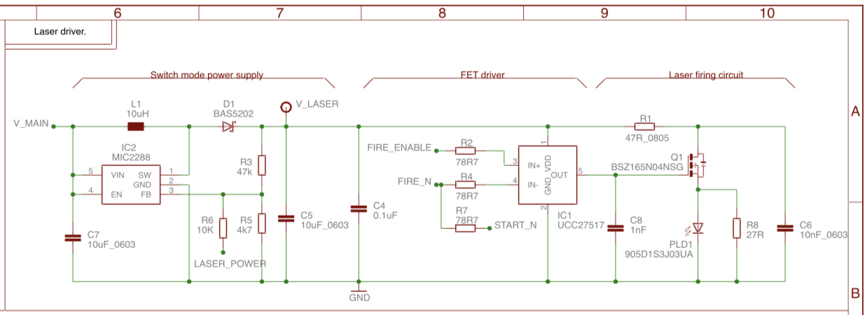
The laser driver circuit has a SMPS (IC2) that converts 5V (V_MAIN) into the laser operating voltage (V_LASER). This higher voltage is needed by the PLD (PLD1) because it doesn’t switch on at lower voltages. V_LASER can be adjusted through the LASER_POWER control line that is connected to DAC A0 on the IBM4 controller board. The voltage can be set from 8V to 19.5V at 12 bit resolution.
CAUTION: Increasing the laser voltage increases the output power of the laser and can result in hazardous laser radiation levels.
To prevent accidental firing of the PLD during power up there is a FIRE_ENABLE signal that goes high when it is safe to fire the laser. The firing signal itself is negative going (FIRE_N) in order to match up with certain timing limitations of the CircuitPython APIs.
FIRE_ENABLE is also used to control the duration of the laser flash by switching the laser off shortly after it is fired. The laser firing signal can be controlled in steps of 8.3 ns with a typical set value of 25 ns resulting in a 15 ns long flash of laser light. The flash is shorter than the firing signal because it takes time for the laser to turn on.
The firing signal is amplified by a FET driver chip (IC1) that switches on a high current FET (Q1) to deliver the drive current to the PLD. This drive current comes from a capacitor (C6) and not directly from the SMPS. This allows the FET to switch a much higher current into the PLD than is available from the V_LASER power rail. The average current consumption on the 5 V rail is 2.5 mA while the peak current through the laser can be more than 10 A.
The shape and amplitude of the drive current through the PLD are determined by the voltage on C6, the duration of the firing signal, the switching speed of the FET and the combined impedance of the FET, PLD, C6 and circuit tracking. The resulting flash of light has a triangular amplitude profile with a steeper edge at the front.
-
6Unruly amplification: Turn up the music!
![]()
The returning photons are focussed onto the APD by a lens and optically filtered to reduce the background noise. The APD converts the photons into electrons but unlike a regular photodiode the APD operates with a high revers bias voltage (130 V). This causes an avalanche effect inside the APD, similar to how a photomultiplier tube works, that amplifies the signal by a factor of 100 or more.
The amplification chain starts with the high voltage power supply that reverse biases the APD to achieve its characteristic high gain. The high voltage is created by a PWM (pulse width modulated) signal (BIAS_PUMP) that switches a high voltage FET (Q2). When the FET is turned on, current rises in an inductor (L6). When the FET is turned off a fly-back effect occurs that dumps the current through a diode (D2) and into a reservoir capacitor (C24). Holding the FET on for longer increases the voltage in the reservoir capacitor. The high voltage is read back by the processor using ADC A3 connected to the BIAS_VOLTAGE signal.
The high voltage supply is smoothed using an RC filter (R10, C28). This removes some of the switching spikes but leaves a low frequency ripple on the supply. To reduce the effects of this ripple, the laser firing is synchronized with the switching of the high voltage FET so that the instantaneous voltage across the APD is the same on successive measurements. In this way the APD bias voltage can be kept stable to better than 100 mV.
The average APD bias voltage is continually adjusted based on the temperature measured by a temperature sensor (IC3). A software control loop manages this adjustment process, keeping the optimal operating voltage on the APD as it warms up and cools down. The APD operates at between 110 V and 160 V but needs very little current so the high voltage circuit draws a mere 2.0 mA from the 5V supply.
The current output from the APD is fed into a TIA (IC4) and converted into a differential voltage. Differential voltages are used to improve immunity from noise coming from other parts of the circuit. The TIA has a differential output impedance of 150 ohms so its bandwidth can be controlled by a capacitor (C23) and its gain controlled by a resistor (R17) in parallel with the terminating impedance.
A variable gain amplifier (VGA, IC5) then makes the signal bigger. The gain of this amplifier can be changed via an SPI interface in order to maximize the SNR (signal-to-noise ratio) of the amplification chain as a whole. The bandwidth of the VGA is controlled by a capacitor (C22) and the gain can be set from -10dB up to +35dB in 3dB steps.
The amplified analog signal is fed into a comparator (IC6) that converts it into a 3.3V digital logic level, thereby creating the “stop” signal for the TDC.
-
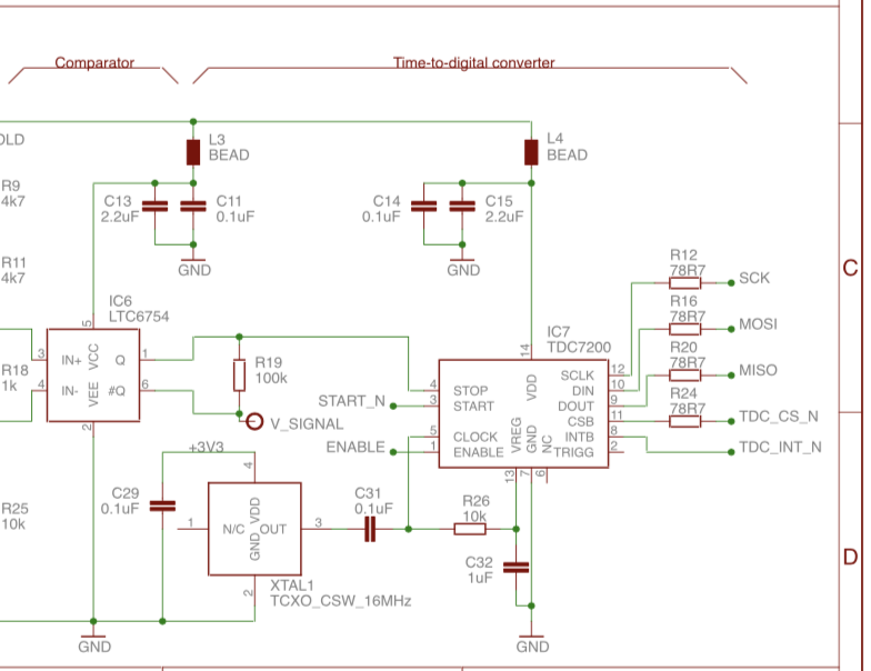
7Unruly timing: You want me to measure what?!
![]()
The timing of the flash of laser light is carried out by a TDC (time-to-digital converter). The TDC has a resolution of 55ps equating to a distance of 8.25 mm based on a round trip at the speed of light. The result has some random noise superimposed so higher resolution can be achieved by averaging a number of readings.
The TDC (IC7) is started by the laser firing signal (START_N) and stopped by the return signal when it comes out of the comparator. The TDC can measure up to 5 stop signals for every start signal as long as they aren't too close together.
The TDC can be configured to read either rising edges or falling edges and the Unruly LiDAR uses this capability to calculate the width of a return signal. This width is a proxy for signal strength and is used to identify strong signals and to apply calibration factors for greater overall accuracy.
Once the TDC has got some results it sets an interrupt flag (TDC_INT_N). Results are collected by the processor using an SPI bus (TDC_CS_N, SCK, MOSI, MISO).
-
8Unruly wake up call: Let's get this party started!
At power on the signal lines from the IBM4 are low and the Unruly LiDAR is not firing the laser or taking measurements. A startup sequence is required to get the circuits ready for measuring:
- The control lines of the IBM4 are initialized and set into a safe startup state.
- The gain of the VGA is set using bit-banged serial data communication. The three data transfer lines are ENABLE (active low), AMP_DATA and AMP_CLK. Typically a gain code of 8 is used resulting to a voltage amplification of 14 dB. Data is transferred MSB first with each bit clocked by a low-to-high transition of the AMP_CLK. Gain control values only work when power saving is disabled.
- If power saving is enabled the VGA defaults to a gain code of 8.
- The comparator threshold is set by outputting a voltage on the THRESHOLD line. This is a signal from DAC A1 of the IBM4 and represents a range of values from 0-161 mV with 50mV being a typical setting.
- Four PWM signals are initialized - AMP_POWER (in power saving mode), FIRE_ENABLE, FIRE_N and BIAS_PUMP. These signals are synchronized and have to be configured at the same time when using the CircuitPython APIs. If they are configured at different times they may end up being driven by different hardware timers and lose their synchronization.
- The APD bias voltage is set by the BIAS_PUMP output. A control loop runs continuously in software to keep the APD at the optimum operating voltage.
- The TDC is reset and configured via the SPI bus.
Once the Unruly is configured the PLD fires continuously, even when measurements are not being taken. This is to make sure that all the relevant signals remain tightly synchronized, providing the most stable and repeatable conditions for the APD, amplifiers and TDC. Losing this synchronization results in poorer performance due to increased noise, unpredictable voltage variations and increased jitter on the timing edges.
-
9Unruly CircuitPython: How to program a snake...
In most embedded projects that mix an electronic circuit with software to make your wonderful widget, the hardware dictates the primary functions and the software is added afterwards to make it all work. This design approach leaves you with lots of coding to do after the hardware is made and somehow that first prototype just drags on forever without reaching the potential you had in mind. This is not the only way....
The Unruly started with a choice of coding language. It had to be a language that anyone could learn quickly without needing advanced coding experience. The Unruly is for hackers, students, scientists and engineers. It would have made no sense to chose a complicated IDE with compilers and linkers and debuggers and a thousand lines of code just to make it say "hello world". So the first decision was to use Python.
The second decision was which processor to use. We wanted something small and of course it needed to run Python. Speed is critical to controlling the LiDAR hardware and we know that anything running slower than 100 MHz is tricky to use but faster than 200 MHz isn't necessary for a simple LiDAR design. The SAMD51 looks like a good choice.
Then along comes Adafruit and creates a branch of Python specifically for the SAMD51 processor. This CircuitPython is a big step forward for Unruly, especially since Adafruit offers breakout boards loaded and ready to run. But, and there's always a but...
Firstly the standard CircuitPython API's provide limited hardware control over the I/Os, DAC, ADC, PWM, SPI, I2C, UART. This isn't enough to control sophisticated LiDAR hardware. Secondly, we looked very closely at the hardware performance of the Adafruit boards and the results were horrible! OK, let me clarify this by saying that when you're running at the speed of light even a jitter of one nanosecond on the clock edges equates to a distance error of 15 cm. The boards we tested had jitter on successive PWM edges in the order of 100 ns. No biggie for a hobby project but a death blow to a LiDAR. However, there are always limitations in any design so take the NASA approach - work the problem!
That leaves us with only one key requirement for the Unruly design and that is to make it insensitive to the software and hardware limitations of the CircuitPython / Adafruit boards. Now we can start.
-
10Unruly signals: S.O.S....
Signal Pin Port Action Description RESETN JP4.14 External reset control +3V3 JP4.13 Digital power line AREF JP4.12 Fixed at 3.3V HVI JP4.11 5V supply for laser and APD LASER_POWER JP4.10 A0 DAC Set laser power THRESHOLD JP4.9 A1 DAC Comparator threshold BIAS_VOLTAGE JP4.8 A2 ADC APD bias voltage T_APD JP4.7 A3 ADC APD temperature TDC_CS_N JP4.6 A4 OUT TDC select for SPI, active low ENABLE JP4.5 A5 OUT Enable TDC/VGA SCK JP4.4 SCK SPI.SCK TDC SPI MOSI JP4.3 MOSI SPI.MOSI TDC SPI MISO JP4.2 MISO SPI.MISO TDC SPI AMP_POWER JP4.1 D2 PWM Reduces power draw of VGA VBAT JP2.1 External battery GND JP2.2 System ground VUSB JP2.3 Not used FIRE_N JP2.4 D13 PWM Laser fire, active low FIRE_ENABLE JP2.5 D12 OUT Enable laser firing, active hig BIAS_PUMP JP2.6 D11 PWM APD bias voltage control TDC_INT_N JP2.7 D10 IN+PU TDC timeout, active low AMP_DATA JP2.8 D9 OUT VGA data: 4 bits, MSB first AMP_CLK JP2.9 D7 OUT VGA clock, low-to-high JP2.10 D5 Servo2 Servo PWM with 5V drive JP2.11 SCL I2C User JP2.12 SDA I2C User JP2.13 TX_D1 UART User JP2.14 RX_D0 UART User JP1.4 D3 I/O User JP1.5 D4 Servo1 Servo PWM with 3.3V drive The table lists all the signals between the IBM4 controller board and the Unruly LiDAR board. In the following sections we will look at each of these signals, see what they do and try to understand how the CircuitPython APIs generate the correct waveforms.
Open Source LiDAR - Unruly
We've been waiting a long time for someone to post the plans of a working LiDAR. Is it really going to happen?

Discussions
Become a Hackaday.io Member
Create an account to leave a comment. Already have an account? Log In.
Hi,
I notice that the bandwidth of the output front end of the APD is 4.4 MHz, (capacitance of APD is 2pF, Rf of MAX3658 is 18kOhm). But the pulse of laser is 15ns, I think a bandwidth of at least 23 MHz is required. Did you sacrifice the pulse response for more gain?
Are you sure? yes | no
Interesting question Lincoln. The gain of a trans-impedance amplifier is modeled using a resistor (18kOhm) but the input does not actually look like a resistor to the APD. Instead the input impedance of the MAX3658 is much lower than 18k, it is 75 Ohm. This makes the cutoff frequency about 480MHz.
Are you sure? yes | no
Thank you. Your reply explains my doubts. And on the page four on the datasheet of MAX3658, the plot of BANDWIDTH vs. INPUT CAPACITANCE also explains this point. But to be clear, I found the input resistance of MAX3658 is actually 400 Ohm, in which case bandwidth is still sufficiently wide.
Are you sure? yes | no
The MAX3658 is an impressive part with very high gain (18.5k Ohms). It has a DC restoration circuit that looks like it is for dark current compensation that would normally be from a PIN diode. Does the APD work well with this circuit? I also assume you can adjust the threshold of the APD by changing the bias through a PWM. Are you doing single returns or averaging a number of them together? Great project!
Are you sure? yes | no
Thanks for the questions John.
Maxim has a family of TIAs that originally came from the fiber optic world - MAX3665, MAX3658 and MAX40658. Each has pro's and con's when used in LiDAR with an APD. It is generally better to run the APD just below the breakdown point so that there isn't too much DC signal entering the TIA. It turns out that this is a good operating point for SNR anyway and can be controlled by the bias PWM as you suggest.
Under most operating conditions a single laser shot is sufficient to give a good result but it is very interesting to see what happens when you start analyzing multiple shots. Not only can you improve the timing resolution but you can also apply statistical methods to a much noisier signal to improve the SNR in ways that seem impossible. For example, analyzing 100 shots gives a 10x improvement in SNR, allowing Unruly to measure signals that are well below the noise floor.
The trick here is knowing that firing the laser faster does not affect the eye safety rating nor does it significantly increase the current consumption. Faster firing = more data. More data = better range.
Are you sure? yes | no
Great project. I could really use one of these. Am using LIDAR-lite (gotten too expensive), a homemade solution using PIN diode and caps charged to light level (proportional-inverse to distance), and cheap phase-shift laser rangefinders from China ($30) whcih has good accuracy but slow response. For $50, this project would take off. I would buy 500 at that cost.
Are you sure? yes | no
Great stuff, welcome to the project!
Are you sure? yes | no
I've seen some articles where they use a 3d printed item to make a 2-part silicon mold (shore hardness ~40) and make polymer castings of the item. They have some very impressive resolutions and it seems like the cost could be cheaper than using a SLA printed version for each one. An injection mold would be a good long term choice, but that's a lot of machining. On plastic vs. glass, is there isn't a huge difference in cost, I'd at least look at the performance of glass. Nicely executed project - I appreciate the detail you put into the schematics (PWB layout impedances, layout geometries, ...). Great project so far!
Are you sure? yes | no
Thanks for the ideas John, I really appreciate the feedback.
We have looked at the 3D printed molding process in the past but I'm not sure that it can deliver the precision that we need - it has to be a three part tool. In any event, we'll probably go the injection moulding route as it only takes a few hundred shots to recover the costs and we want to get the price as low as possible to make the Unruly available to students.
We have compared glass and plastic lenses (we had both types custom made and ran side-by-side tests) and were surprised at how good the plastic lenses were. I personally prefer the plastic because the lenses are unbreakable and probably more suited to an experimental environment. Crash!
Are you sure? yes | no
Even though the optical design is simple, do you have a posting with the prescriptions, spacing and filter bandwidth?
Are you sure? yes | no
Not yet, but it's coming. We've chosen a design that uses plastic (acrylic) lenses with AR coatings and these along with the filter are custom made. Since we have already invested in the tooling for these parts we can offer them to hobbyists or other interested parties at really low cost.
The optical holder hasn't been tooled yet and we are currently 3D printing it. This tool will be quite expensive so unless we get enough interest it will remain an expensive part.
Are you sure? yes | no
Who is supplying these lenses?
Are you sure? yes | no
Just simply STUNNING!!
Are you sure? yes | no
Thanks martin! Please feel free to chip in with comments or suggestions :).
Are you sure? yes | no