 Laser Developer
-
11Unruly measurements: What does a return signal look like?
![]()
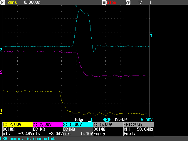
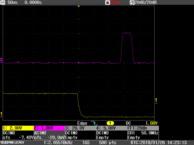
The yellow trace is the FIRE_N signal that triggers the laser driver circuit on the falling edge. The red trace (LeCroy has their own idea as to what red is) shows the return signal after the comparator. The time scale is 50 ns per division.
The first vertical cursor shows the approximate moment when the laser fires. This is shortly after the FIRE_N signal due to delays in the firing circuit.
There are three return signals:
- The first return is the window about 8 m away across the room. It is tinted glass to keep the African sun out but some of the laser flash penetrates the glass.
- The second return is from a tree across the yard. It is 112 ns away equating to a distance of 17 m. This tree has fairly dense foliage but there are small gaps between the leaves to let some of the light continue on its journey.
- The third return is from a tree in the neighbor's yard. This is 282 ns away equating to 42 m. You can see that this return is getting weaker (narrower) because there isn't much laser light getting through.
To make things more interesting it is currently 29 deg C outside with a cloudless sky - the sun is really bright. This demonstrates how effective the optical filter is in removing background light. Thanks Tracy!
-
12Unruly firing signals: How to make a 20ns pulse using CircuitPython.
![]()
To pulse the laser diode a short duration "firing signal" is needed. Short is a relative term and in this case the right degree of shortness is about 20 nanoseconds. This is a little tricky to do directly in software so Unruly uses some of CircuitPython's hardware APIs to produce the signal.
It starts by creating two PWM (pulse width modulated) signals as follows:
FIRE_ENABLE = pulseio.PWMOut(board.D12, frequency=2048, duty_cycle=65203)
FIRE_N = pulseio.PWMOut(board.D13, frequency=2048, duty_cycle=65200)These two commands, when written directly one after the other, invoke a specific hardware timer/counter in the SAMD51. Both PWM signals use the same physical hardware and this is really critical to minimizing the relative edge jitter of the signals.
During our hardware examination of the IBM4 we found that ABSOLUTE edge positions move around all over the place by 100s of nanoseconds. But RELATIVE edge positions, when coming from the same internal hardware, can be stable to within 10s of picosecond as long as the edges are close together. I leave it to the reader to figure out how close these edges need to be to retain their relative positions. Suffice it to say that if you want to make a pulse 20ns long then you can get picosecond precision on the width of the pulse using the commands above.
In the oscilloscope screen shot, the yellow trace shows the falling edge of the FIRE_N signal (active low). A short time later the blue trace, which is the laser firing signal, starts to rise (active high). Some time later the red trace falls. This is the LASER_ENABLE signal (active high) and by turning this signal off the laser firing signal gets cancelled and the blue line eventually turns off.
Some of you may be concerned with the mismatch between the edges of the signals. They don't line up because, at the speeds we are dealing with, time delays through fast electronic components become very significant.
For the moment we will ignore these delays and concentrate on the unlikely result which is that we have used CircuitPython to generate an extremely stable and accurate laser firing signal that is just over 20ns long. Changing the duty cycle of the FIRE_ENABLE changes the width of the firing signal in 8.3ns steps.
-
13Unruly APD: How to make a silent 120V switching power supply.
The APD (avalanche photodiode) of the Unruly is an amazing light detector that is about 100 times more sensitive than a normal photodiode. It works similar to a photomultiplier tube using a high bias voltage (110V - 160V) that lets a single photon produce numerous electrons.
The bias voltage is produced by another PWM channel that drives the BIAS_PUMP line. This PWM is linked to the same internal hardware of the SAMD51 as the FIRE_N signal by writing the CircuitPython code as follows:
FIRE_ENABLE = pulseio.PWMOut(board.D12, frequency=2048, duty_cycle=65203)
FIRE_N = pulseio.PWMOut(board.D13, frequency=2048, duty_cycle=65200)
BIAS_PUMP = pulseio.PWMOut(board.D11, frequency=2048, duty_cycle=1800)The duty cycle of the BIAS_PUMP determines the bias voltage on the APD and like all switch mode power supplies the circuitry generates unwanted electrical interference and leaves some residual ripple on the DC voltage. This "noise" can dramatically reduce the performance of the LiDAR.
![]()
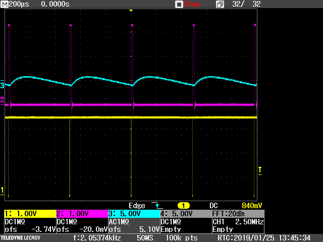
In the oscilloscope image above the yellow trace is the FIRE_N signal, the red trace is the BIAS_PUMP signal and the wiggly blue trace is the bias voltage. There is 2V ripple on the bias line, an artifact of the switching nature of the high voltage supply.
The Unruly eliminates this ripple by always firing the laser at the same relative time in the high voltage switching cycle. Zooming in closer:
![]()
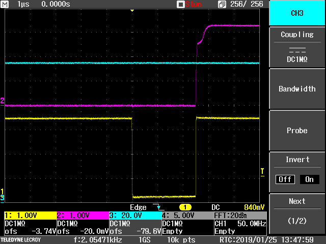
The yellow trace is FIRE_N and is active on the falling edge at which time the laser produces a flash of light. After this firing edge the BIAS_PUMP signal (red trace) is inactive for 2.5 us so that there is a silent period while the flash of laser light is traveling - 2.5 us equates to 375m of measuring range.
After the measuring time the BIAS_PUMP becomes active and it can generate as much noise as it wants because the measurement is over. Notice that when the laser fires there is no apparent ripple on the blue trace of the high bias voltage. This is because of the tight synchronization between the FIRE_N signal and the BIAS_PUMP signal.
-
14Unruly amplification: Grab a few photons and stop the timer. Easy!
Now that we have fired the laser and applied a high bias voltage onto the APD, the amplifier chain of the Unruly can take the energy of the returning photons and amplify it to a level that can stop the TDC. This process takes four hardware amplifying elements.
The first amplifying element is the APD itself. It converts the photons into electrons, producing a small current. Even though the APD is 100 times more sensitive than a regular photodiode (a gain of 100), the resulting current is too small to measure directly using an oscilloscope. A "big" signal would be a few micro amperes.
Stage two is a bit easier to measure. This is the TIA (transimpedance amplifier) that converts the APD current into a differential voltage. The Unruly TIA has a gain of 18300, converting a 1uA signal from the APD into 18.3mV.
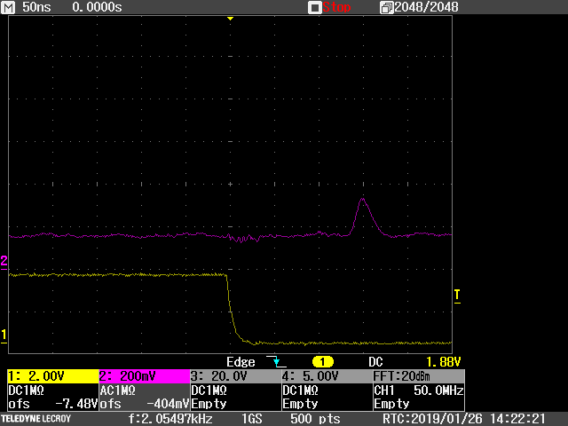
Looking at one side of the TIA output voltage is the red trace below:
![]()
The falling edge of the yellow trace is the laser firing signal. You can see that this induces lots of noise in the TIA signal. The TIA eliminates this "common mode noise" and leaves behind the "differential signal." In this test the actual signal is the small bump at three divisions after the firing edge.
The third amplification stage is the VGA (variable gain amplifier). The signal above is amplified 10 times (20dB) to reveal the signal below.
![]()
You can see how effective the amplifier chain has been in reducing interference from the firing of the laser and other sources of electrical noise. It has been designed to amplify the return signal and attenuate interference.
The gain of the VGA can be set in software through a serial port. The Unruly uses a simple bit banged method as follows:
# ---- Set the gain code of the VGA from 0 to 15 ----
# Can only be used with power always on, not low power mode
def VGA_gain(gain):
ENABLE.value = False # Enable VGA communication
AMP_DATA.value = gain & 0x08 # Output bit 3
AMP_CLK.value = True # Clock cycle
AMP_CLK.value = False
AMP_DATA.value = gain & 0x04 # Output bit 2
AMP_CLK.value = True # Clock cycle
AMP_CLK.value = False
AMP_DATA.value = gain & 0x02 # Output bit 1
AMP_CLK.value = True # Clock cycle
AMP_CLK.value = False
AMP_DATA.value = gain & 0x01 # Output bit 0
AMP_CLK.value = True # Clock cycle
AMP_CLK.value = False
ENABLE.value = True # Disable VGA communicationThe fourth and final amplification stage is the comparator. It takes the analog signal coming from the VGA and converts it into a 3.3V logic signal to stop the TDC. The comparator has a settable detection threshold and in this experiment it is 50mV, giving the comparator an effective gain of 66 times. The comparator threshold is set by an analog signal coming from DAC A1:
# ---- Set the comparator threshold from 0mV to 161mV ----
def COMP_threshold(thr):
if thr > 161:
thr = 161
THRESHOLD.value = int(thr * 405.143) # 65536 / 161.76 at 12 bitIn the red trace below the signal has become a clean logic level event:
![]()
The performance of the amplifier chain can be compared with the performance of a standard photodiode connected to a 50 ohm resistor. This relative gain is calculated as follows:
Relative gain = APD gain x TIA gain x VGA gain x comparator gain / photodiode gain
= 100 x 18300 x 10 x 66 / 50
= 2415600
= 128dB
This is astoundingly good performance from a few basic components.
-
15Unruly timing circuits: TDC or not to TDC, that is the question...
The Unruly uses a conventional TDC component to perform the timing of the laser flashes. This is not the only way to do LiDAR timing.
Advanced LiDAR systems, such as those found in surveying systems operated from aircraft, use "full waveform analysis" and convert the entire signal into a digital image using high speed ADCs. This is an expensive and power hungry approach but the results are astonishing. A lot of detail about atmospheric transmission, foliage, surface textures, unlimited number of returns and signal strength can be collected using this method. In most cases the data isn't analyzed in real-time but is post-processed to provide the beautiful 3D maps that LiDAR is known for.
At the other end of the scale, tiny system-on-a-chip LiDARs are available that provide short distance measurements at low cost. These systems may work on different principles such as phase measurement or single-photon counting. In this case the end justifies the means in that it isn't necessary to know more about the return signal than the distance.
The Unruly fits between these two extremes in that it can be configured to behave in different ways. To detect the presence of an obstacle all that is needed is a reliable signal (high SNR) and this can be achieved by keeping background noise to a minimum (reduce the APD bias voltage and set a high detection threshold on the comparator). Alternatively, the gain can be set higher to allow noise to mix in with the measurements and mathematical analysis can be applied to recover the return signal or signals in surprising detail and at very long range.
Every application is different requiring specific combinations of update rate, range, resolution and permitted error rate. The Unruly is designed to help experimenters explore these characteristics in real-world tests so that you can understand what combination provides the best solution. The Unruly is not designed to be perfect, it is designed to be flexible and easy to use.
Open Source LiDAR - Unruly
We've been waiting a long time for someone to post the plans of a working LiDAR. Is it really going to happen?


Discussions
Become a Hackaday.io Member
Create an account to leave a comment. Already have an account? Log In.
Hi,
I notice that the bandwidth of the output front end of the APD is 4.4 MHz, (capacitance of APD is 2pF, Rf of MAX3658 is 18kOhm). But the pulse of laser is 15ns, I think a bandwidth of at least 23 MHz is required. Did you sacrifice the pulse response for more gain?
Are you sure? yes | no
Interesting question Lincoln. The gain of a trans-impedance amplifier is modeled using a resistor (18kOhm) but the input does not actually look like a resistor to the APD. Instead the input impedance of the MAX3658 is much lower than 18k, it is 75 Ohm. This makes the cutoff frequency about 480MHz.
Are you sure? yes | no
Thank you. Your reply explains my doubts. And on the page four on the datasheet of MAX3658, the plot of BANDWIDTH vs. INPUT CAPACITANCE also explains this point. But to be clear, I found the input resistance of MAX3658 is actually 400 Ohm, in which case bandwidth is still sufficiently wide.
Are you sure? yes | no
The MAX3658 is an impressive part with very high gain (18.5k Ohms). It has a DC restoration circuit that looks like it is for dark current compensation that would normally be from a PIN diode. Does the APD work well with this circuit? I also assume you can adjust the threshold of the APD by changing the bias through a PWM. Are you doing single returns or averaging a number of them together? Great project!
Are you sure? yes | no
Thanks for the questions John.
Maxim has a family of TIAs that originally came from the fiber optic world - MAX3665, MAX3658 and MAX40658. Each has pro's and con's when used in LiDAR with an APD. It is generally better to run the APD just below the breakdown point so that there isn't too much DC signal entering the TIA. It turns out that this is a good operating point for SNR anyway and can be controlled by the bias PWM as you suggest.
Under most operating conditions a single laser shot is sufficient to give a good result but it is very interesting to see what happens when you start analyzing multiple shots. Not only can you improve the timing resolution but you can also apply statistical methods to a much noisier signal to improve the SNR in ways that seem impossible. For example, analyzing 100 shots gives a 10x improvement in SNR, allowing Unruly to measure signals that are well below the noise floor.
The trick here is knowing that firing the laser faster does not affect the eye safety rating nor does it significantly increase the current consumption. Faster firing = more data. More data = better range.
Are you sure? yes | no
Great project. I could really use one of these. Am using LIDAR-lite (gotten too expensive), a homemade solution using PIN diode and caps charged to light level (proportional-inverse to distance), and cheap phase-shift laser rangefinders from China ($30) whcih has good accuracy but slow response. For $50, this project would take off. I would buy 500 at that cost.
Are you sure? yes | no
Great stuff, welcome to the project!
Are you sure? yes | no
I've seen some articles where they use a 3d printed item to make a 2-part silicon mold (shore hardness ~40) and make polymer castings of the item. They have some very impressive resolutions and it seems like the cost could be cheaper than using a SLA printed version for each one. An injection mold would be a good long term choice, but that's a lot of machining. On plastic vs. glass, is there isn't a huge difference in cost, I'd at least look at the performance of glass. Nicely executed project - I appreciate the detail you put into the schematics (PWB layout impedances, layout geometries, ...). Great project so far!
Are you sure? yes | no
Thanks for the ideas John, I really appreciate the feedback.
We have looked at the 3D printed molding process in the past but I'm not sure that it can deliver the precision that we need - it has to be a three part tool. In any event, we'll probably go the injection moulding route as it only takes a few hundred shots to recover the costs and we want to get the price as low as possible to make the Unruly available to students.
We have compared glass and plastic lenses (we had both types custom made and ran side-by-side tests) and were surprised at how good the plastic lenses were. I personally prefer the plastic because the lenses are unbreakable and probably more suited to an experimental environment. Crash!
Are you sure? yes | no
Even though the optical design is simple, do you have a posting with the prescriptions, spacing and filter bandwidth?
Are you sure? yes | no
Not yet, but it's coming. We've chosen a design that uses plastic (acrylic) lenses with AR coatings and these along with the filter are custom made. Since we have already invested in the tooling for these parts we can offer them to hobbyists or other interested parties at really low cost.
The optical holder hasn't been tooled yet and we are currently 3D printing it. This tool will be quite expensive so unless we get enough interest it will remain an expensive part.
Are you sure? yes | no
Who is supplying these lenses?
Are you sure? yes | no
Just simply STUNNING!!
Are you sure? yes | no
Thanks martin! Please feel free to chip in with comments or suggestions :).
Are you sure? yes | no