Pavel
Pavel-
The Control Panel
01/23/2019 at 06:21 • 1 commentBuilding the Arithmetic Unit is great, but as it is there is no simple way to assess its workings. As I've built it, I am personally know what to look at, but for most outside people, the shining of the LEDs on the board is still cryptic. Also, by no means it is obvious for me at the first glance. And giving inputs by connecting individual wires is a pain.
So, the solution for this is simple interface, Control Panel (CP) with switches and indicator lights for switch states and output from the circuit to which it is connected.
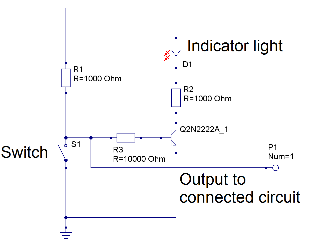
For each individual switch, there is a simple circuit:
![]()
The values of resistors directly connected to the transistor may vary depending on the colour of LED.
I decided to make this control panel look pretty, and for this , it is composed of two boards, one with switches, lights and connectors ("face board"), and other with all transistors and most of resistors ("driver board").
It turned out to be quite a lot of work, because there are so many wires I needed to solder.
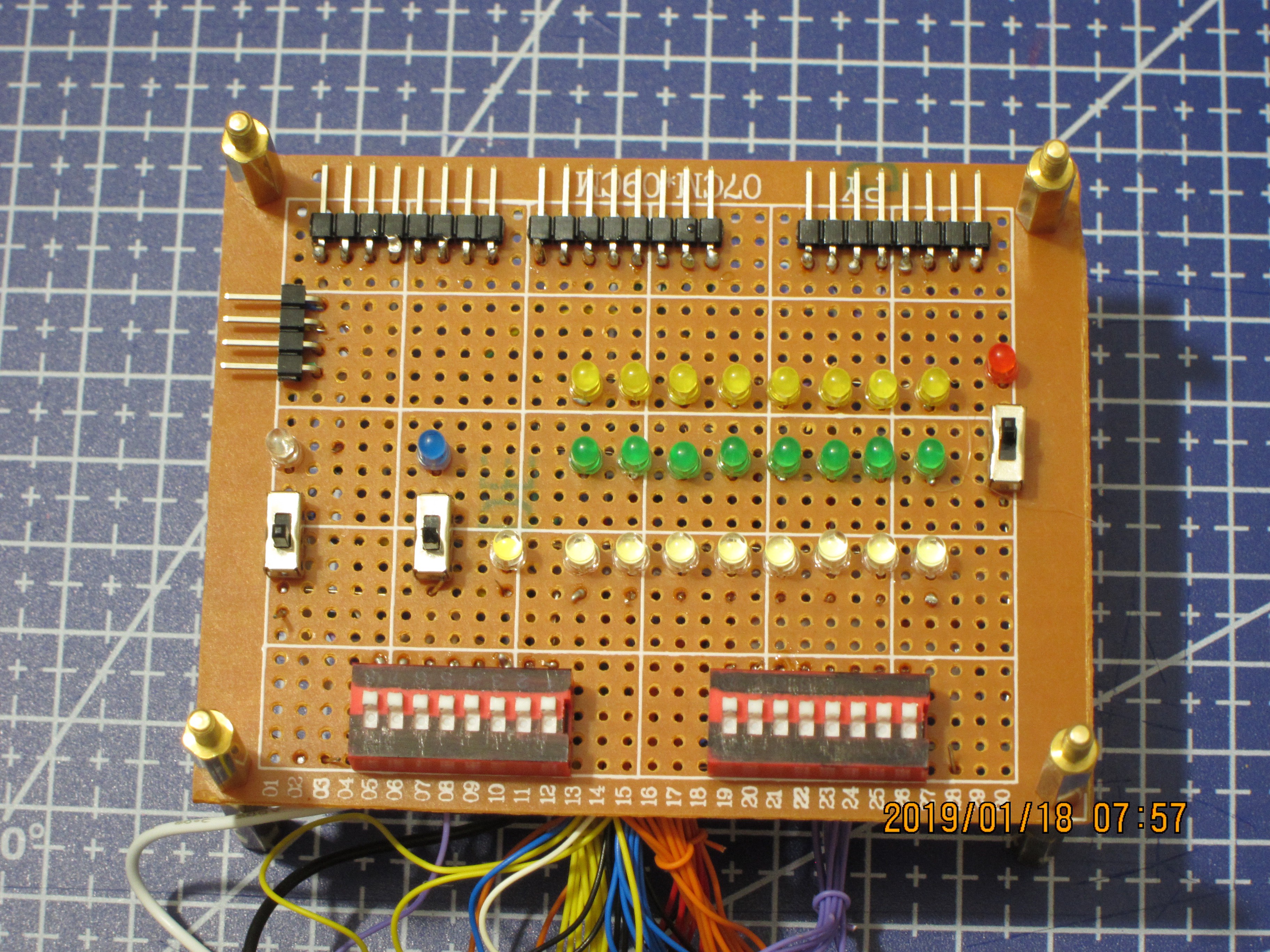
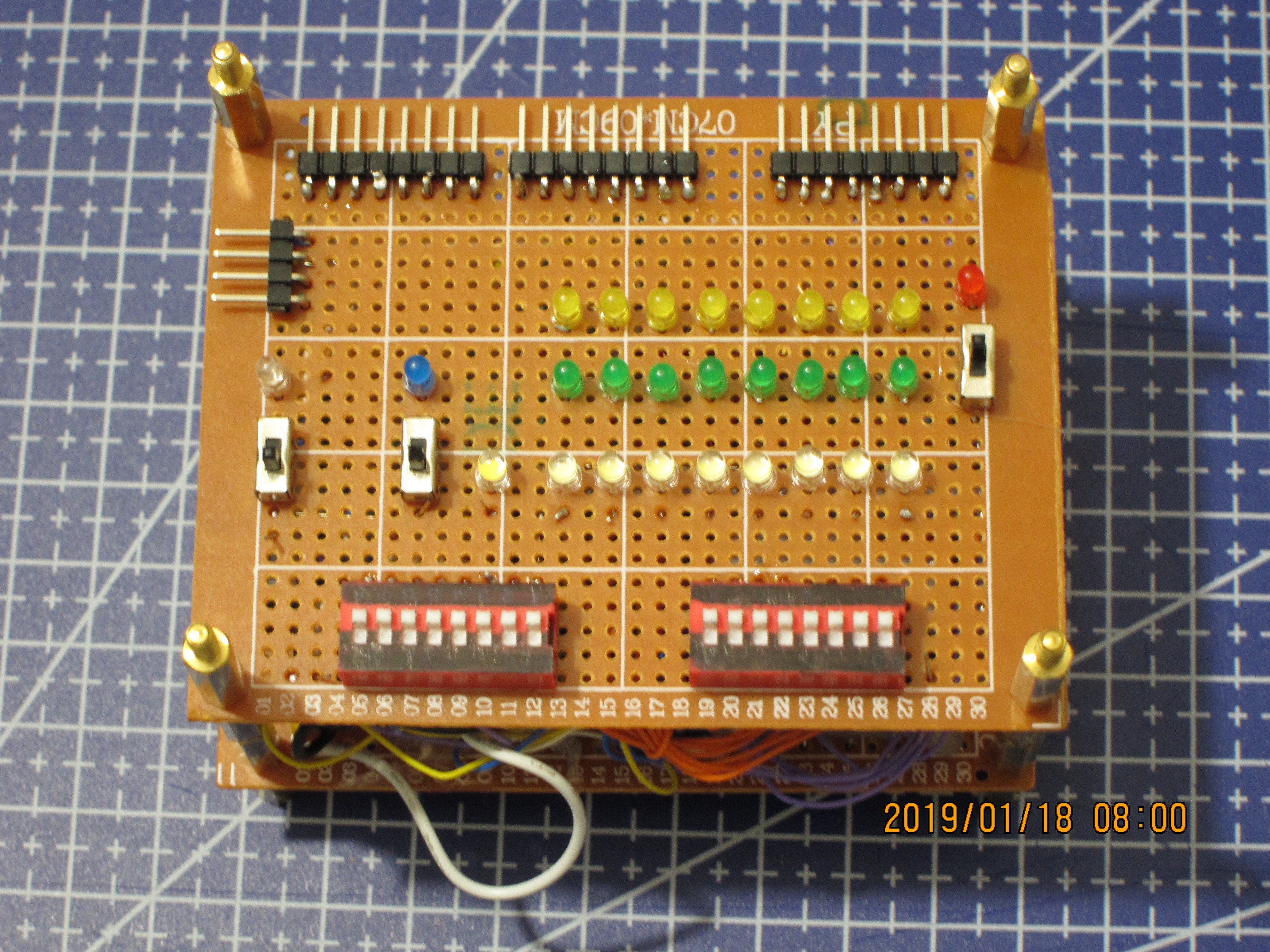
So, here is the "face board":
![]()
Connectors:
Facing left, 4 pin, signals, from top to bottom: Carry_out (coming to the CP), Carry_in, Carry_in_enable, Sub/Inv B
On the top, from left to right:
8 bit operand A - coming out of CP;
8 bit operand B - coming out of CP;
8 bit Result - coming into the CP.
Switches and associated lights:
Individual switches:
Leftmost, with clear Red LED - Carry_in_enable,
Closer to light rows, with coloured Blue LED - SUB/INV,
Rightmost, with coloured Red LED - Carry_in.
Switch banks:
Left -- operand A, associated with the top row, Yellow, LEDs,
Right -- operand B, associated with the middle row, Green LEDs.
Lights indicating incoming signals -- bottom row, 9 White LEDs:
The leftmost, Warm White, near SUB/INV switch: Carry_out,
The rest 8, Cold White: Result.
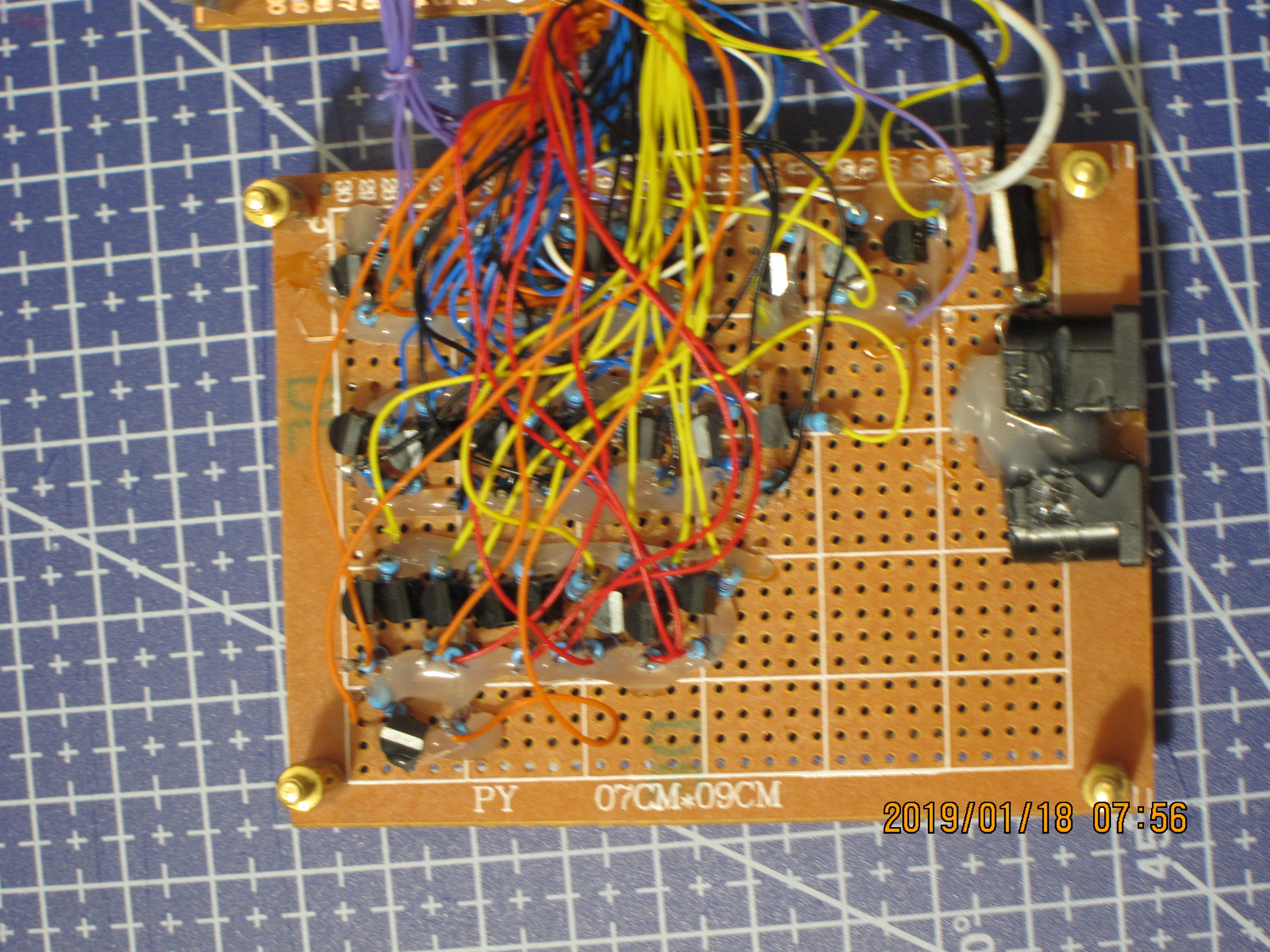
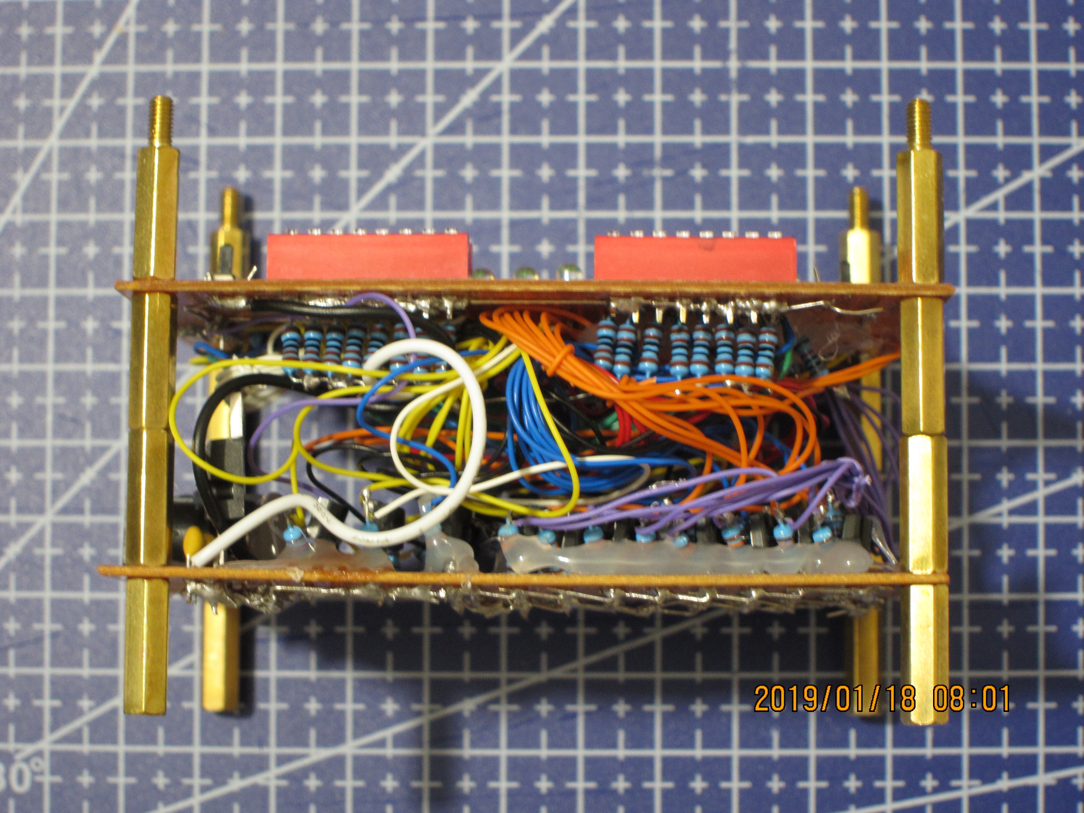
And the "driver board":
![]()
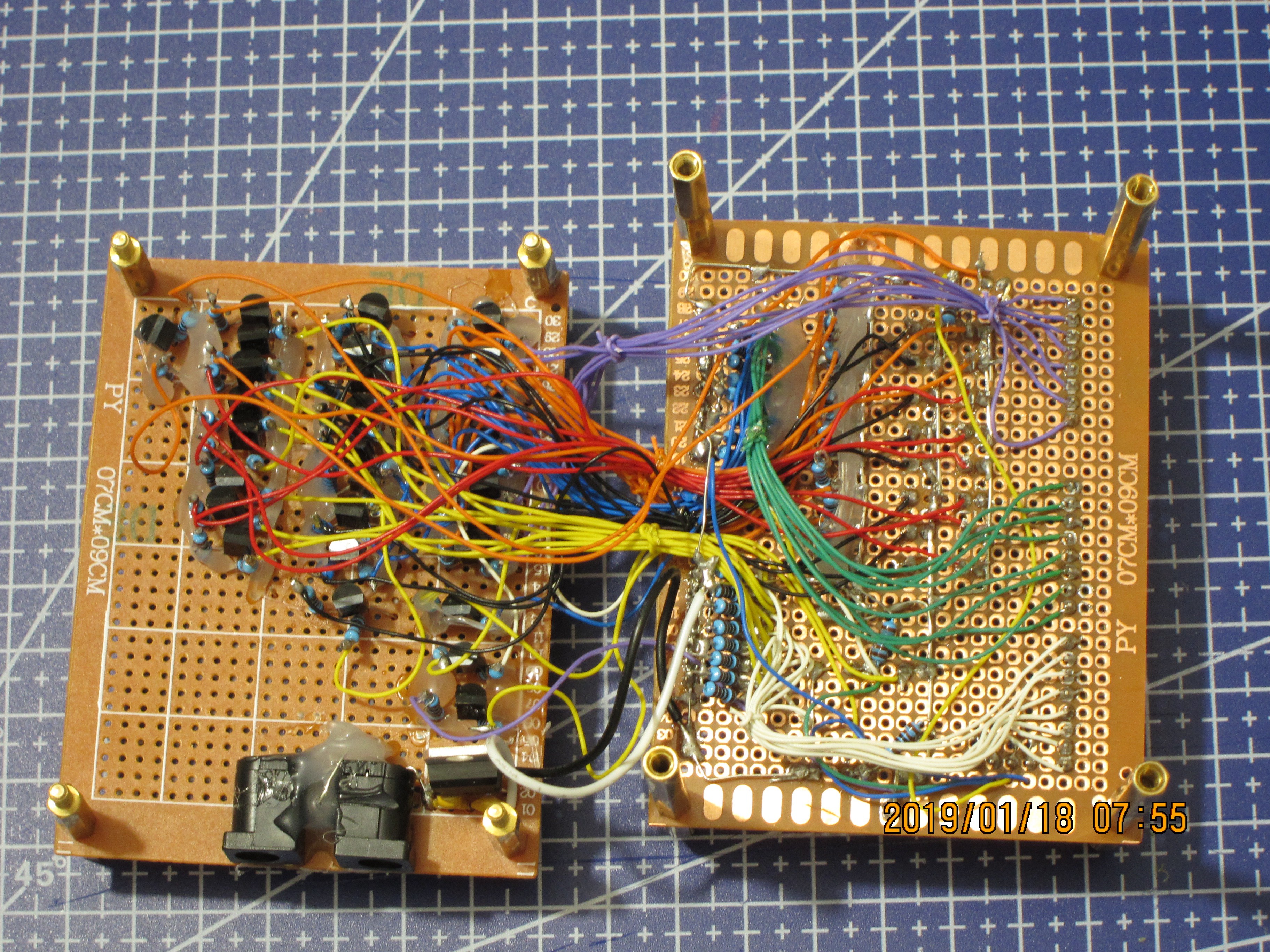
On this overview one can see these boards connected with a bunch of wires:
![]()
When the boards are stacked, it all looks prettier:
![]()
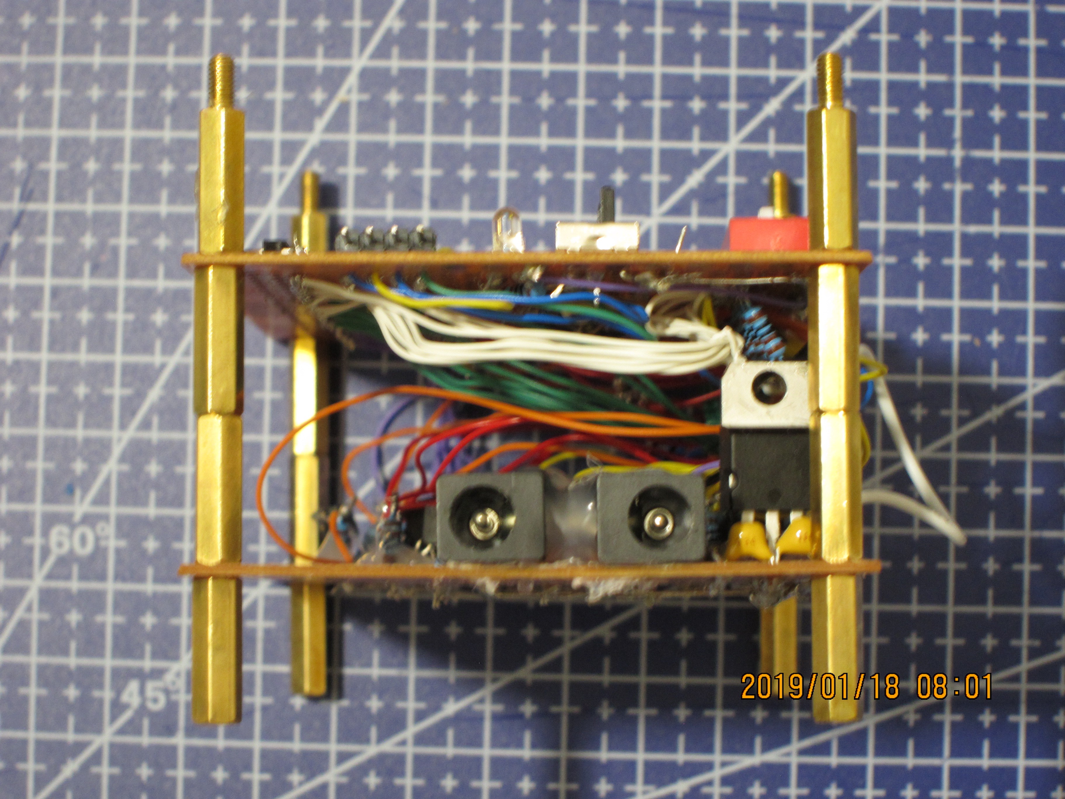
View from the sides:
![]()
![]()
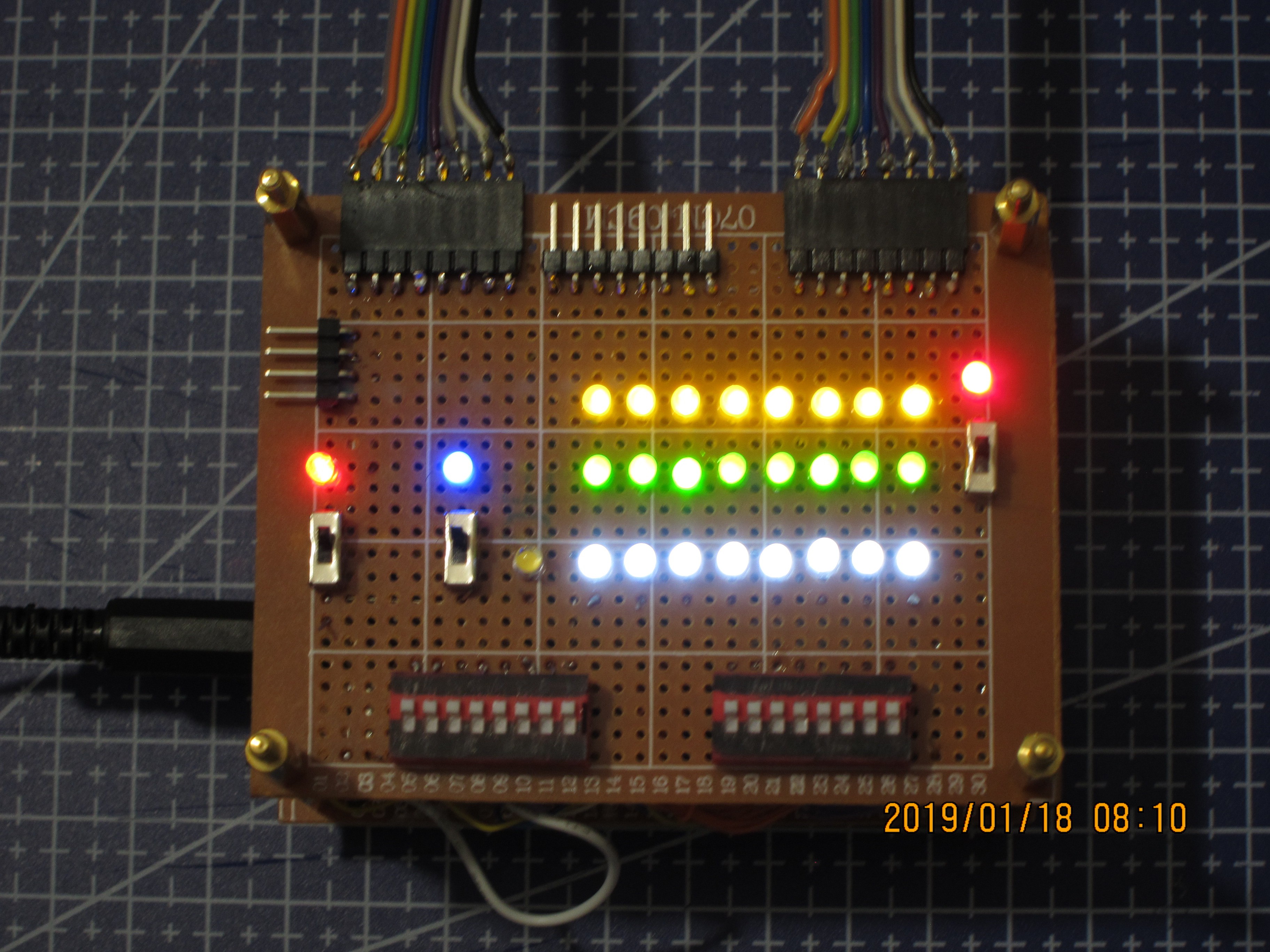
Testing all the lights (except for C_out):
![]()
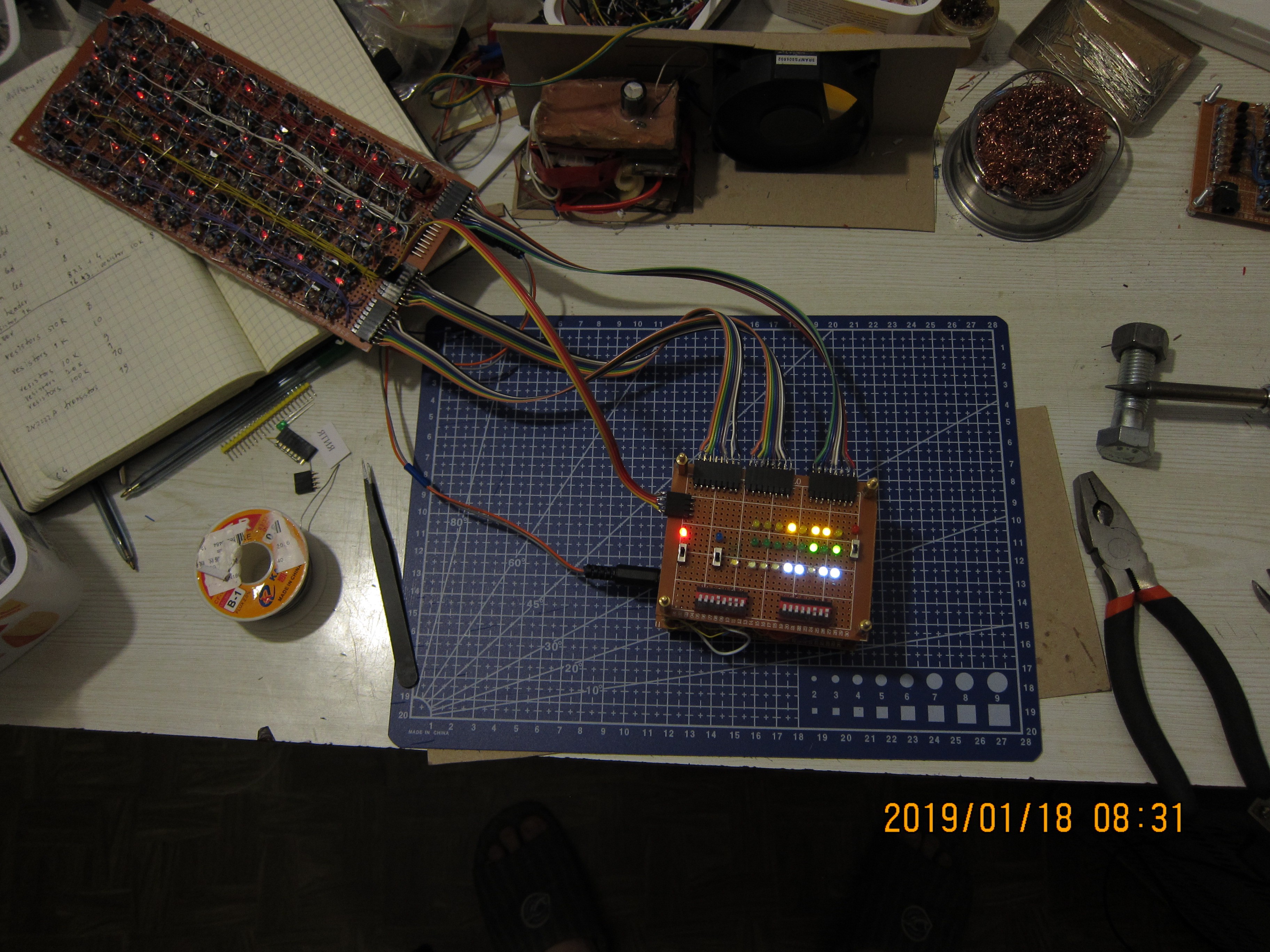
After all the teasing, below there are image of this Control Panel connected to the Arithmetic Unit:
![]()
And the video showing how it all works together.
Total parts count for the Control Panel:
Part name count Perfboard 30*24 holes (9*7 cm) 2 2N2222A npn transistor 19 Resistor 510R 8 Resistor 1k 28 Resistor 10k 17 Resistor 20k 1 Resistor 100k 10 Red LED (clear) 1 Red LED (coloured) 1 Blue LED (coloured) 1 Yellow LED (coloured) 8 Green LED (coloured) 8 Warm White LED (clear) 1 Cold White LED (clear) 8 SPDT switch (connected as spst) 3 DIP bank of 8 SPST switches 2 L7805 Voltage regulator 1 Capacitor 0.1uF 1 Capacitor 0.33uF 1 Pin headers x8 3 Pin headers x4 1 Power connector 2 Total parts 127 -
Arithmetic Unit
01/22/2019 at 06:46 • 0 commentsThe ALU (Arithmetic Logic Unit) is arguably is a heart of any CPU, which is doing the operations on the bits and bytes of data.
Here I am making an Arithmetic half of it, the circuit which, in my case, is going to do additions and subtractions on 8-bit binary numbers.
For it I am using only NAND gates, which are the smallest DTL gates I can make from discrete components -- and these already 7 parts per gate.
Lets start to build up this unit.
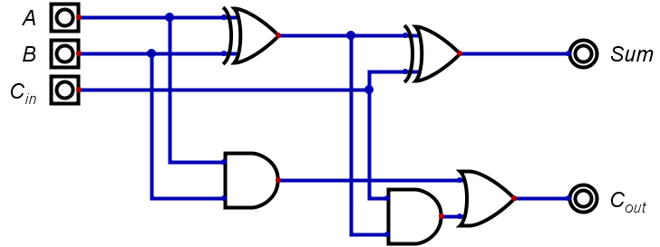
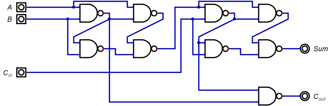
Here is the classical schematic for a full adder:
![]()
Here no NAND gate in sight. But theoretically, one can make any other gate from NANDs, so this should not discourage us. We can substitute XORs by groups of 4 NAND gates:
![]()
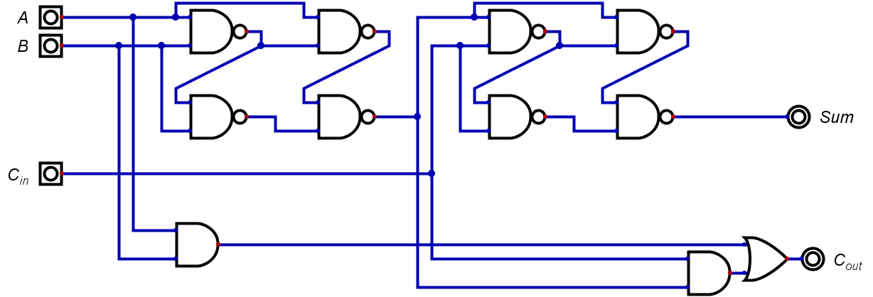
And we can also easily substitute AND-OR combination with NAND-NAND, and logical function will stay the same:
![]()
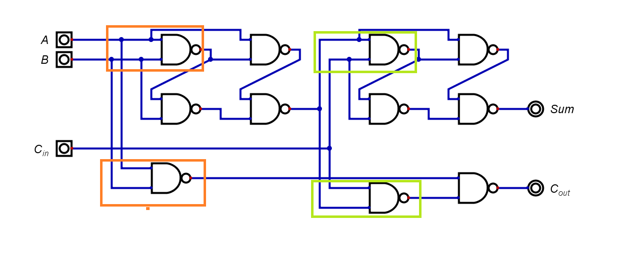
And now, one can see that highlighted pairs of NAND gates are doing exactly the same work, and we can safely eliminate two of them without compromising the whole circuit:
![]()
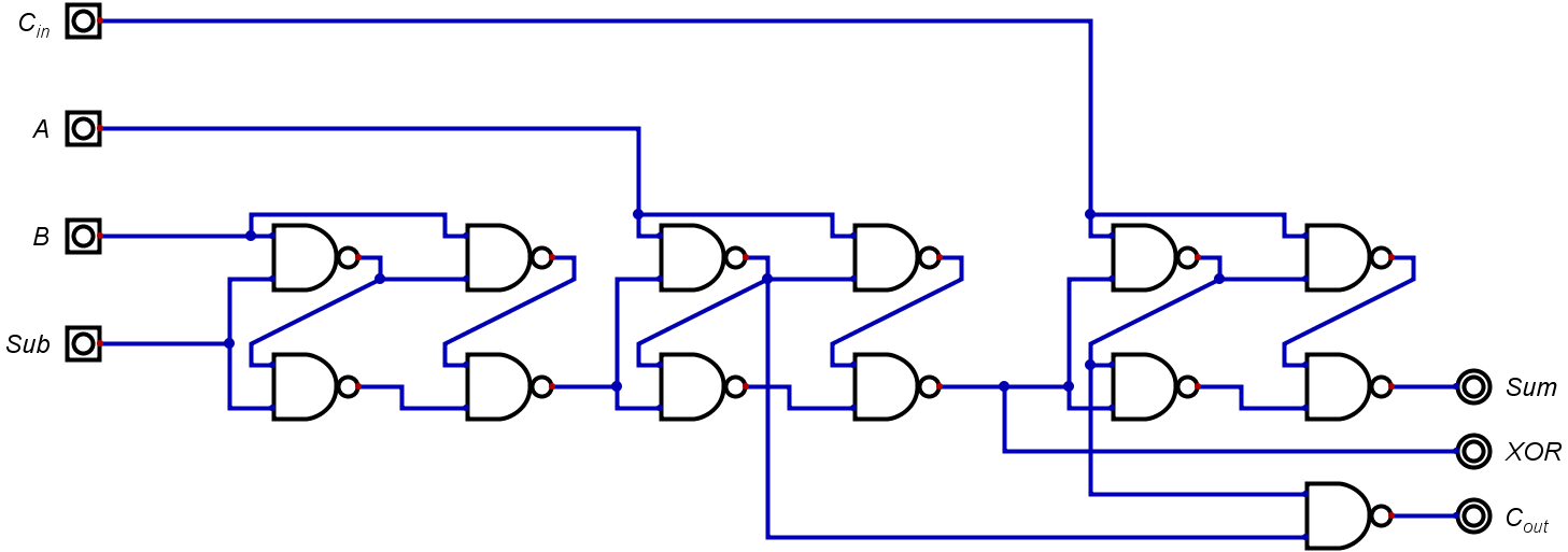
For the unit to do subtractions, we need a way to conditionally invert the B input - and this can be done with just one other XOR gate, which in this case will also be 4 NAND gates instead:
![]()
After stacking 8 of these units, and making conditional inverting on Carry in +adding C_in enable we are having a full-fledged 8-bit ripple adder-subtractor. If we are also using output from the middle XOR group (right before C_in input), we than have a "free" XOR/XNOR functionality.
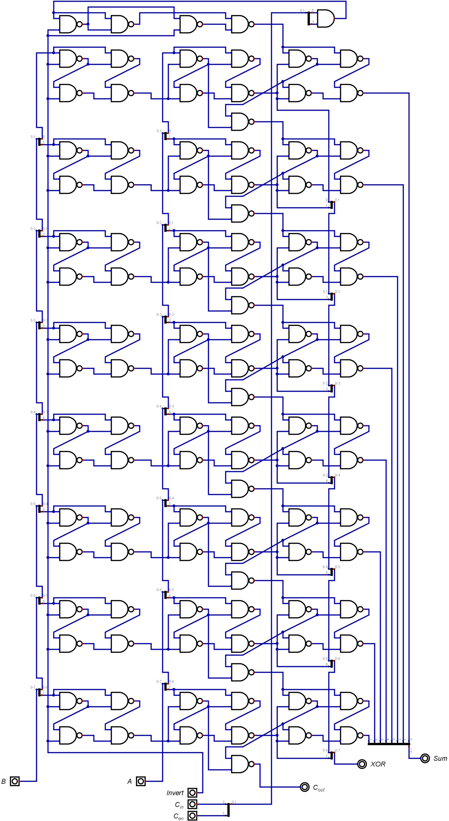
On the completion of this stacking we are getting this:
![]()
This configuration of gates is almost exactly the same as on the actual board.
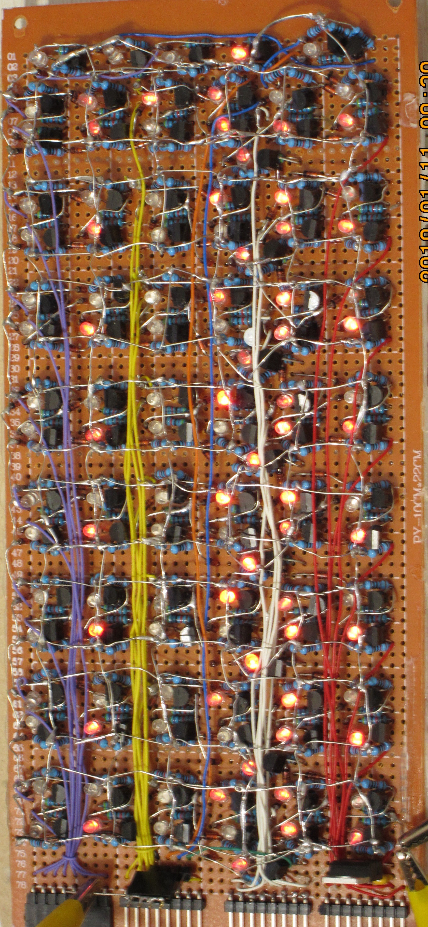
Implementing this the way I do, the board looks like this:
![]()
On the photo is a complete board during testing. The only additional parts are L7805 voltage regulator with a pair of caps on the lower right, near alligators.
Pin headers are used as convenient connection points; this was done for connecting with some other boards in the future, most prominently, with control panel, which will be described in the next log.
Here is parts count for this board:
Part name count Perfboard 78*36 holes 1 2N2222A npn transistor 110 1N4148 diode 218 Resistor 10k 110 Resistor 20k 109 Resistor 47k 109 Red LED (clear) 109 L7805 Voltage regulator 1 Capacitor 0.1uF 1 Capacitor 0.33uF 1 Pin headers x8 4 Pin headers x4 1 Power connector 1 Total parts 775
Simple ALU from discrete components
Prototyping some processor functions using logical gates made of discrete transistors, resistors and diodes