 Bud Bennett
-
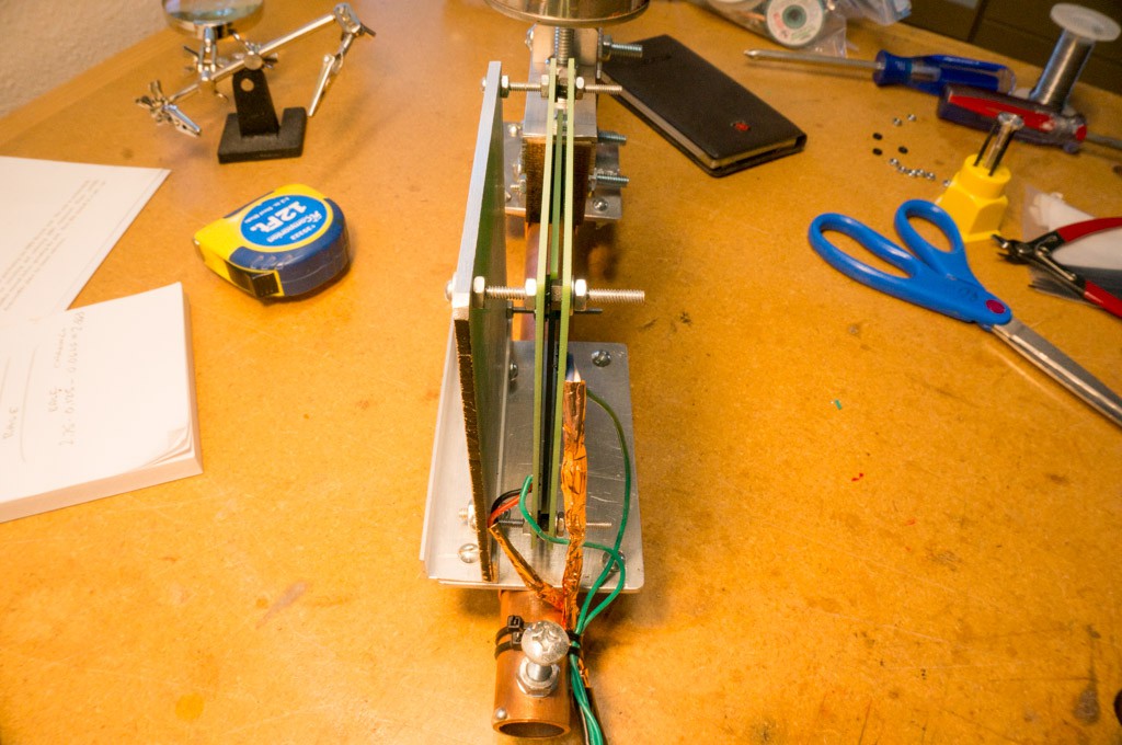
11Mount the Sensor Stators
Solder 18” long 24 AWG stranded wire into the three holes in each stator plate. I used red/black/green for the T1/T2/GND of the exciter plate. I used white/blue/green for the T1/T2/GND of the capacitor plate.
Insert a 1.5” long 4/40 machine screw through the back of the sensor mount plate at the upper left, lower left, and lower right positions (when viewing from the left side of the seismometer). Secure the 3 screws agains the plate with a 4/40 nut. Add another 4/40 nut over each screw and then slide the exciter stator plate over the three screws. You will need to move the boom/rotor plate out of the way in order to accomplish this. Adjust the nuts contacting the stator plate so that the plate is about 1mm equidistant from the rotor plate. Make sure that the stator is aligned so that the rotor is centered over the stator -- you might need to slide the sensor base on the frame to accomplish this.
Insert a 1.5” long 4/40 machine screw into the upper right hole and secure with a 4/40 nut. This screw should have two nuts added to it before it passes through the exciter stator plate. Adjust the second nut to align the stator plate about 1mm from the rotor plate.
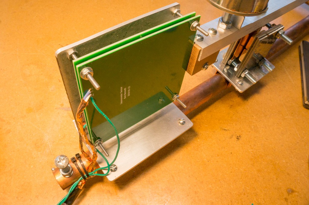
Slide 3.5mm spacers over the 4 screws and then mount the capacitor stator plate over the four screws. Spin four 4/40 nuts over the four screws to secure the stator plate against the spacers. My spacers are a 1mm thick M3 nylon washer and a M3 nylon nut, which is 2.5mm thick.
Adjust the 4/40 nuts that contact the stator plate until the gap between the rotor plate and the stator plates is the same at the four corners. Tighten the nuts.
![]()
![]()
A warning: if you move the seismometer after this point you could cause the rotor plate to collide with the screws and go out of alignment. I use a piece of tape across the boom and stator plate to prevent the boom from swinging when moved.
-
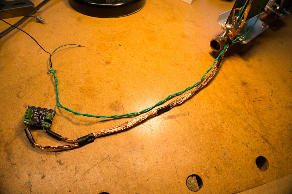
12Connect the Electronics
Connect the exciter wires to the EXCA and EXCB terminals of the cap2dig converter. Connect the signal wires from the capacitor plate to the CAP terminals of the cap2dig converter. Leave the GND wires unconnected for now.
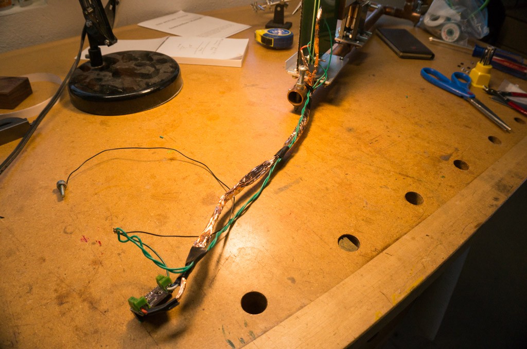
Wrap the each set of wires in metal foil. I used copper tape with conductive adhesive, but aluminum foil will work as well. You don’t need to wrap the GND wires.
![]()
Tape the two foil wraps together to prevent unraveling. Then wrap the wires again with foil.
![]()
I connected the two ground wires together with a short wire to the GND terminal of the cap2dig converter. I also ran a wire to earth ground and connected a clip lead from the grounds to the metal foil shield after the seismometer was installed in its enclosure.
-
13Build the Enclosure
You need to enclose the seismometer to prevent air drafts and temperature variations from destroying the data.
The sides of my enclosure are made from sandwiched layers of 1" thick insulation board, known as TUFF-R™. The board is covered on both sides with a very thin metal foil (aluminum, I believe). The insulation foam is polyisocyanurate and has an R-rating of 5 per inch. I also glued eight pieces of gypsum sheetrock between the insulation boards and also to the inside of the enclosure to give it more thermal mass and keep the rate of temperature swings to a minimum. The sheetrock panels are glued, using construction adhesive, to the insulation boards and the corners of the enclosure are taped together with metal foil tape (it doesn't have to be very sturdy). Any gaps between the insulation boards were filled with expanding foam spray to prevent any air movement between the inside and outside of the enclosure. Walls of the enclosure are 3" thick.
The dimensions of the enclosure are:
Inside 24.75" x 9" x 15" high
Outside: 31" x 15" x 15" high.
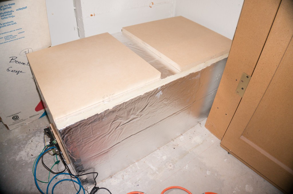
The top is a piece of insulation board cut to the outside dimensions with two pieces of scrap wood glued on top just to weigh it down. Here's what the enclosure looks like in-situ:
![]()
![]()
Cut an inverted "V", about 1/2" x 1/2", into the bottom of the front of the enclosure to allow the sensor cabling to escape the enclosure.
Glue a 4" x 6" piece of 1/2" thick wood to the front of the enclosure an inch or so above the "V" for the cable. Attach the Raspberry Pi computer to the block as shown below.
![]()
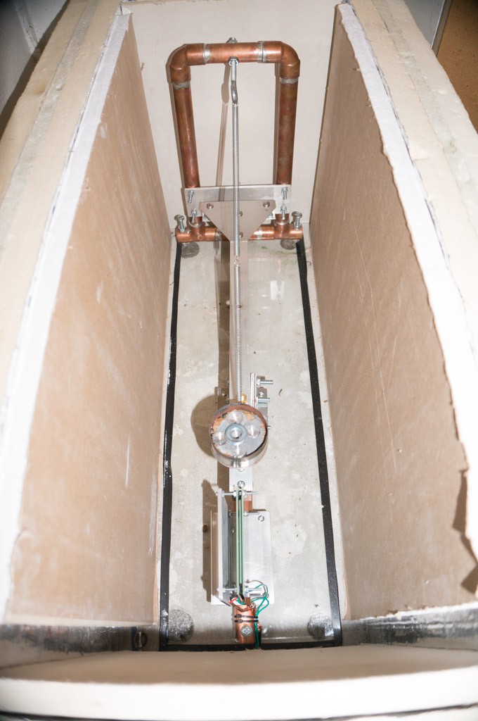
My seismometer rests on a piece of glass, rather than the floor. I am paranoid about thermal expansion/contraction causing bumps and jiggles if the seismometer is sitting on a rough concrete surface -- the glass is the smoothest surface available. Get a piece of single pane glass cut to 8" x 24". Tape the edges with electrical tape to prevent them from cutting yourself. Put a dab of flexible sealant at each corner of the glass and press the glass with the sealant facing down to the floor where you will locate the seismometer. Don't use too much sealant -- it is very difficult to remove without damaging the glass (I use a very thin wire to cut through the sealant if I need to remove the glass. Having less to cut through is better than more.)
Place the enclosure on the floor, centered over the glass. Lower the seismometer onto the glass. It should not touch any part of the enclosure. Raise the front of the enclosure (the block of wood that you glued on the front makes for a good hand hold) and thread the cabling under the "V" and connect the Cap2Dig converter to the Raspberry Pi.
Turn on the Raspberry Pi and adjust the seismometer output to be between ±1 million counts by adjusting either the front leveling screw or the eyebolt. Verify that all is well with the network connection to the Raspberry Pi, then place the top on the enclosure and walk away -- you're done!
Just a note: It will take up to two days for the seismometer to settle out from being disturbed either by mechanical movement or temperature change. Be patient.

Discussions
Become a Hackaday.io Member
Create an account to leave a comment. Already have an account? Log In.