 Bud Bennett
-
1Building the Frame
- Cutoff two pieces of copper pipe 11" long, one 22", one 4 1/8", and two 1.5". Use a pipe cutter for this, it will make nice square edges.
- Drill a 1/4" hole through the center of the 4 1/8" piece for the eyebolt.
- Insert the 1.5" long pipe as connectors between the three tees. They should allow the tees to butt up against each other with no gaps. Insert the 11" pipes into the outer tees and attach the elbows to the other end with the 4" pipe. The 11" pieces should be parallel to each other -- if not, then you might have to shorten the length of the 4" pipe or make a brace help with alignment later.
- You can drill the 1/4" holes for the legs now, or wait until everything is soldered up, depending upon what drill type you have. I drilled the two leg holes in the outer tees at this point since it was easier to do that with a drill press before the frame was assembled. Try to get the hole aligned with the tee, but it's not that critical if you're off a degree or two.
- Time to solder the frame together. You will need a propane torch, plumbing solder, acid flux paste, and a cheap brush to apply the flux. The disposable flux brush is usually sold next to the flux paste. Apply a generous coat of flux paste to both the outside end of the pipe and the inside of the elbow or tee. You can either clamp it all together and solder it, or do it piece-by-piece, but make sure that the base is at right angles to the back support and that the two back pieces are parallel to each other. Also, line up the hole you drilled in the 4" piece with the proper angle for the spring -- it is not critical, but make a good effort here. You solder each joint by heating up the joint with the torch while pressing the end of a length of solder against the joint seam until the solder melts a flows into the joint. Make sure that the entire joint is filled with solder. I'm sure there are plenty of YouTube videos to explain the procedure. Keep wet rags over the nearby joints to prevent them from loosening as you apply heat.
- Let the frame cool, then clean it thoroughly to remove any residual acid flux paste.
- If you didn't drill 1/4" holes for the legs previously, then do it now. At this point I soldered 1/4x20 nuts to the bottom of the frame for each leg bolt, but you could glue them on if preferred. If you want to solder the leg nuts then use a bolt to hold the nut to the frame and cover the bolt and other parts of the frame with a wet rag to keep them cool. Apply flux paste to where the nut and pipe join or the solder will not flow properly. Don't get flux on the bolt. Clean clean it off afterward.
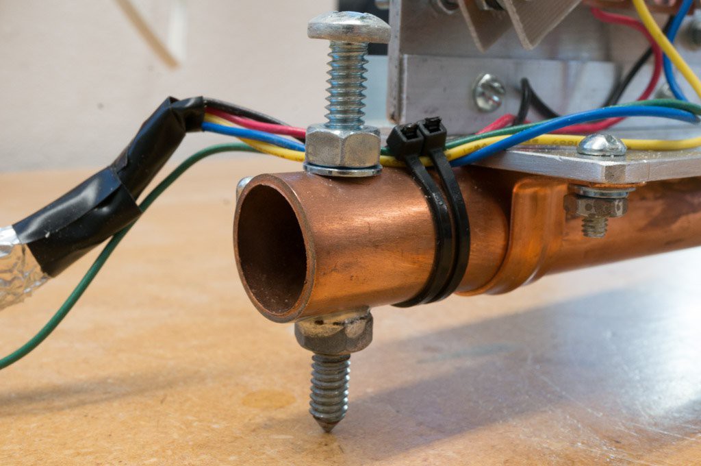
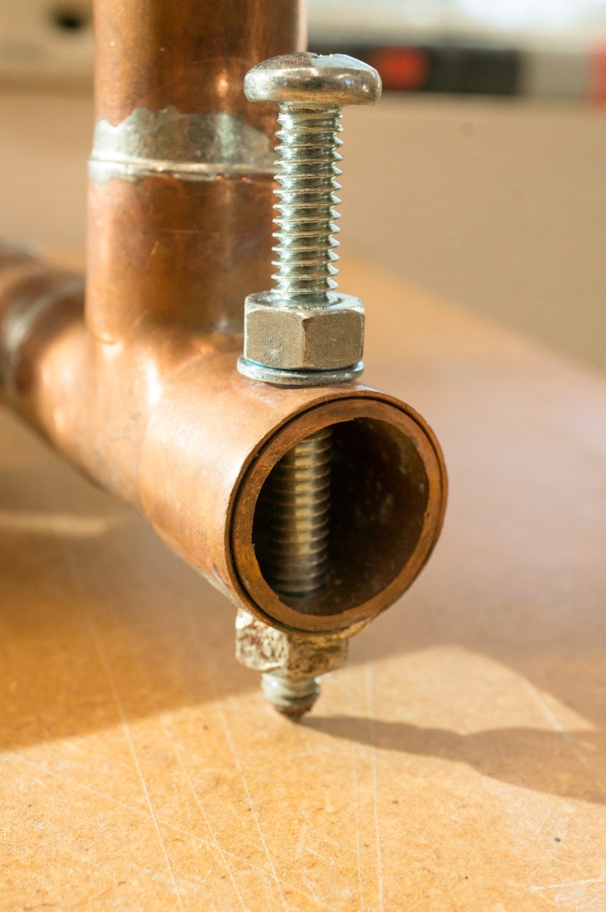
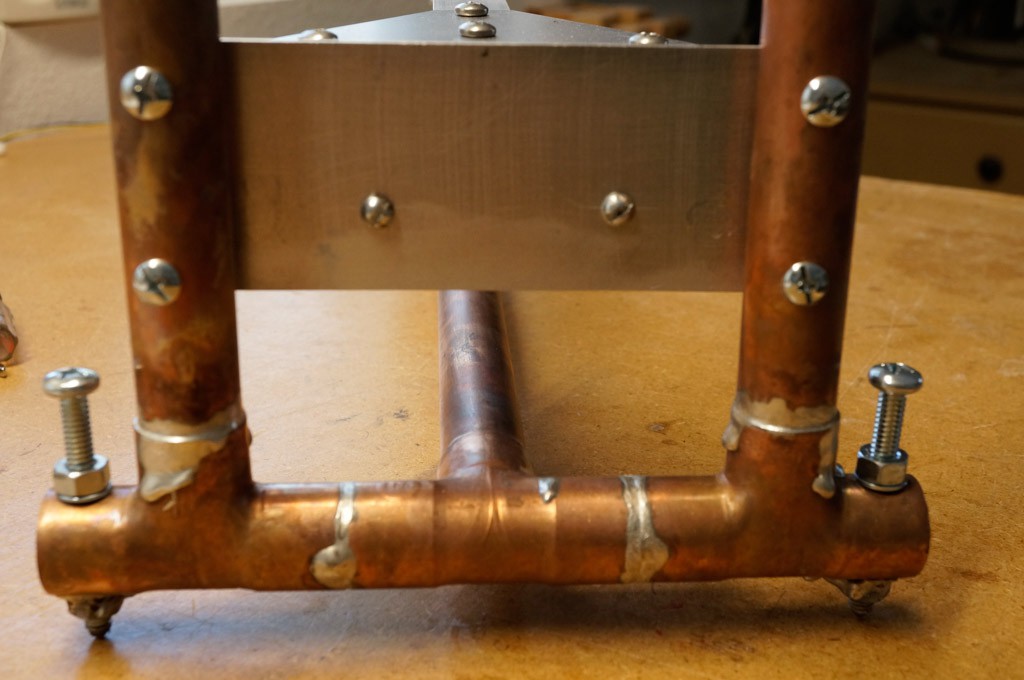
Here's detail photos of the legs. The legs aren't perfectly aligned, but it's not critical.
![]()
![]()
I placed a short piece of pipe inside the tee to reinforce it since the tee is pretty thin. Also all of the legs have been ground to a dull point.
-
2Attach the Eyebolt
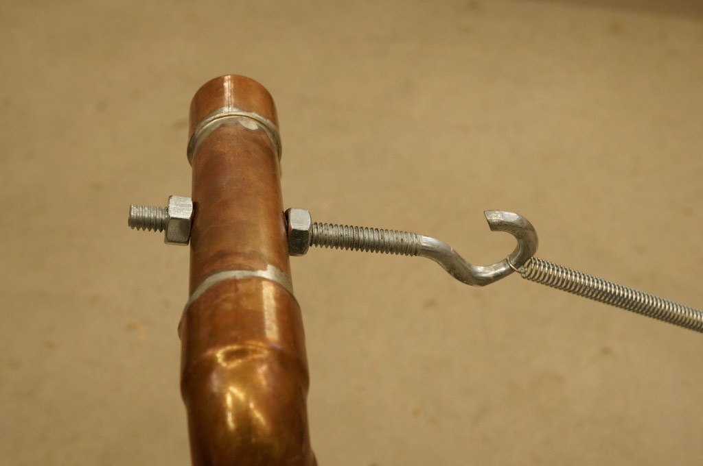
![]() Cut the last bit of the eye to form a hook instead. The spring has a small loop at the end so you may have to grind the point of attachment at the hook to fit. I also filed a groove on the inside of the hook for the spring to sit so that it would not move and create unwanted artifacts. It is desired to have the spring only touching that groove. You can do all of this later, when the position of the spring will be more easily determined.
Cut the last bit of the eye to form a hook instead. The spring has a small loop at the end so you may have to grind the point of attachment at the hook to fit. I also filed a groove on the inside of the hook for the spring to sit so that it would not move and create unwanted artifacts. It is desired to have the spring only touching that groove. You can do all of this later, when the position of the spring will be more easily determined. -
3Make the Hinge
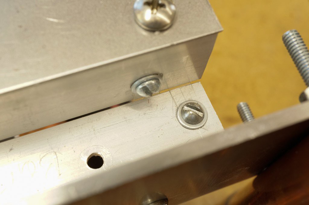
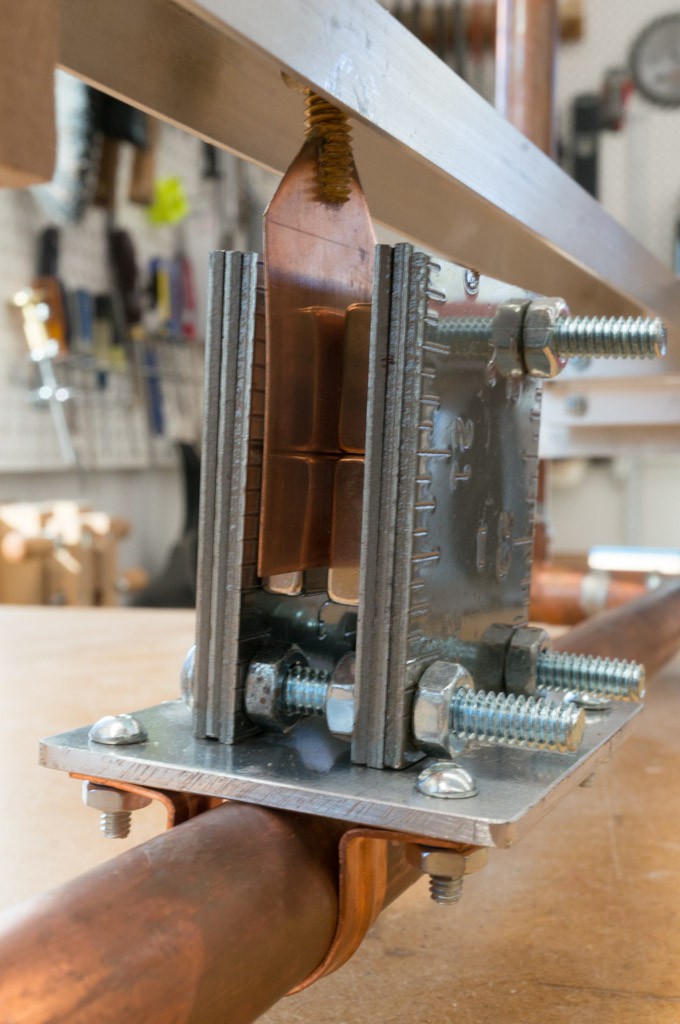
It is easier to show a photo of the hinge than to describe it. Here’s a view of the entire hinge.
![]()
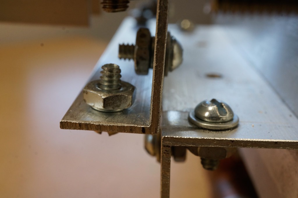
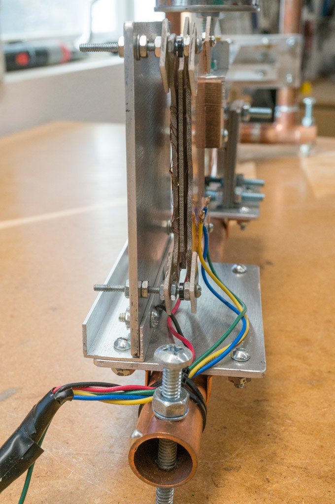
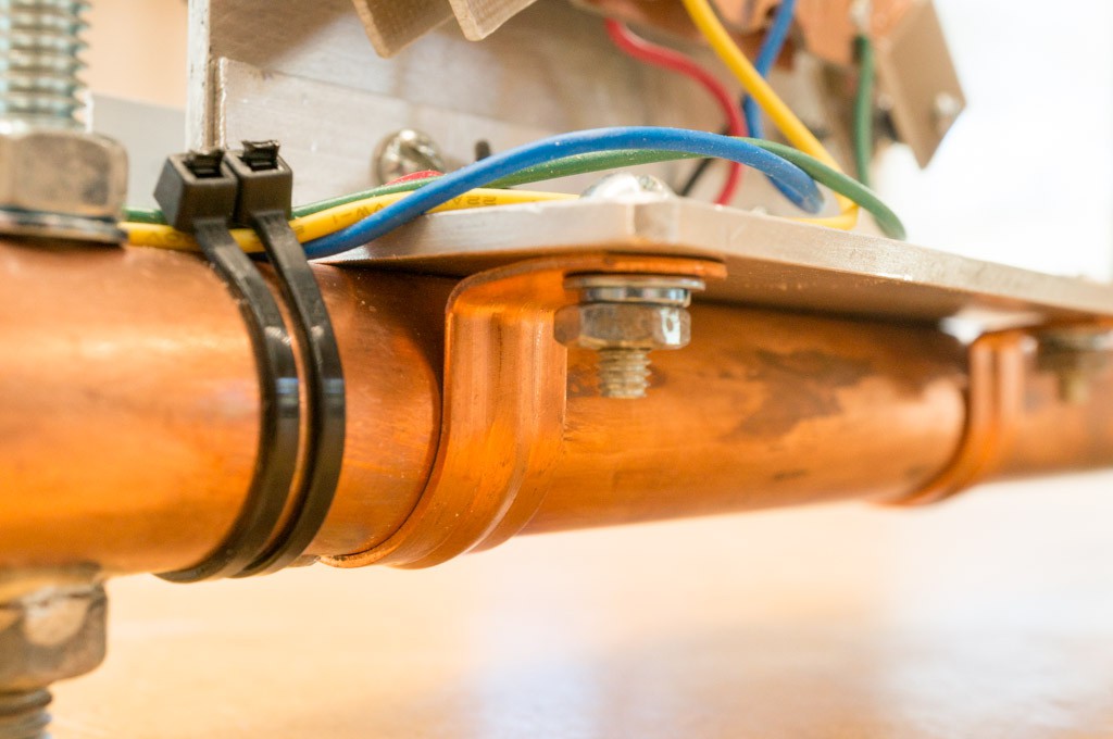
The hinging material is actually 4 straps of plastic made from blister pack — that tough plastic used to encase stuff for sale like SD cards or small hardware pieces. The straps are mounted on two 4” pieces of aluminum channel — the upper channel has its channel facing forward, while the lower channel is facing downward. Two of the straps, the outer straps, are set horizontally, while the inner straps are vertical. Together the straps allow the joint to flex up or down easily while preventing side-to-side movement. Here’s two more details of the hinge arrangement.
![]()
![]()
The plates that are used to connect the hinge to the boom and the hinge to the frame should be made first.
The plate that connects the hinge to the frame is a 6" x 2 1/8" piece of 1/8" aluminum. Drill two holes 3/4” from the bottom spaced 2” from each end of the long side. Don't drill the holes to mount it to the frame yet.
![]()
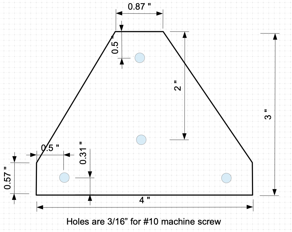
Use this drawing for the hinge-boom plate.
![]() My drawing software can't make fractional dimensions. The 0.87" translates to 7/8", 0.57" is 9/16" and 0.31" is 5/16".
My drawing software can't make fractional dimensions. The 0.87" translates to 7/8", 0.57" is 9/16" and 0.31" is 5/16".- Cut the hinge-boom plate from the 22gauge flat steel plate and drill 3/16” holes for #10 machine screws at the marked locations.
- Cut 2 pieces of aluminum channel 4 inches long.
- Align the hinge-boom plate with the piece that will become the top hinge channel and drill two holes in the channel using the holes drilled at the back of the hinge-boom plate as a guide.
- Align the channel piece that will become the bottom hinge channel to be centered over the two holes drilled in the hinge-frame plate -- take pains to keep the bottom of the channel and the hinge-frame plate parallel. Drill two holes into the channel piece using the holes in the hinge-frame plate as a guide. You can do this operation later, but this way you don't have to worry about damaging the hinge.
- Align the 2 channels and mark lines across both channels where the centers of the hinges should be placed — the outer hinges are approximately 1/4” from the channel ends, and the inner hinges are 5/8” in from the channel ends. Drill holes on the marked lines 5/16” from the channel edges facing toward the hinge point. The holes should be sized for the 3/8” #6/32 machine screws that will hold the straps in place.
- Make 4 hinge straps from blister pack material. These should be approximately 5/16” x 7/8” with slots cut in each end like the photo below.
![]()
Attach the 4 straps to the channel pieces with 3/8" #6/32 machine screws. Use flat washers between the head and the hinge strap. Use a split washer under the nut. Try to keep the space between the two channel pieces as small as possible since this will reduce the side-to-side movement of the hinge. See the hinge detail photos above.
Set the hinge assembly aside for later.
-
4Make the Boom
- Cut a piece of aluminum channel 14 7/8" long.
- Measuring from the hinge side of the boom, drill a 1/4" hole, centered in the boom, at 11" and another at 13 3/8".
- Measuring from the hinge side of the boom, drill a hole, centered in the boom, for a #10 machine screw at 12 5/8"
- Measuring from the sensor end of the boom, drill two holes for 1/2" #8 sheet metal screws, centered in the boom, at 5/16" and 15/16".
- Cut a piece of aluminum channel whose length is a wide as the boom. Cut off on side of the channel to create an "L" shaped bracket. Drill a hole near the top to attach the spring and another centered in the other side for a #8 sheet metal screw. Attach the bracket to the boom with a 1/2" #8/32 machine screw.
- Cut a 3/4" thick piece of hardwood to 1 1/4" x 1 1/4". Stand the block on its thin edge and drill a 1/8" hole from top to bottom 3/4 from one edge. This will create a bit of springiness to hold the rotor blade of the sensor. Turn the block on the thin side with the hole closer to the table. As accurately as you can, saw a slot down the center of the block to meet the hole. Drill a 9/64" diameter hole through the block near the bottom of the slot for a bolt that holds the tongue of the sensor rotor blade. If this was confusing, see this detail.
![]()
Drill two pilot holes prevent splitting then screw two 1/2" #8 sheet metal screws to attach the block to the boom.
Align the boom at right angles to the hinge assembly with the two holes in the hinge-boom plate centered in the boom. Using the holes drilled in the hinge-boom plate, drill two 3/16" holes through the top of the boom. Attach the boom to the hinge with two 3/8" #10/32 machine screws.
-
5Make the Mass Holder
I used an empty tomato paste can to hold the lead weight of the mass. (A tomato sauce can is too wide.)
- shorten the can to be approximately 1.5" tall.
- drill a 1/4" hole in the center of the bottom of the can.
- push a 1.5" long 1/4 x 20 bolt into the hole so that the threads extend out the bottom of the can.
- thread a 1/4 x 20 nut onto the bolt and tighten against the bottom of the can.
- thread 2 more nuts onto the bolt -- these will hold the mass to the boom.
You need about 400g of lead to balance the spring near the middle of the eyebolt adjust range. I used lead fishing weights, but I found that most auto repair shops have a bucket of lead weights that they have removed from tires -- you can get as much as you need for free.
Set the mass holder and lead weights aside until we balance the pendulum later.
-
6Make the Damping Unit
The magnetic damper consists of a copper blade that moves through a strong magnetic field produced by 4 very powerful neodymium magnets. The copper blade and brass bolt are non-magnetic, but the housing IS MAGNETIC so the magnets can stick to it as are the spacer bolts and nuts.
The damping unit is identical to that described in this article. I even used the steel framer's square for the metal case to hold the magnets. Four Neodymium magnets were purchases from K&J Magnetics, Inc. -- Part No. BX0C4.
![]()
- Use a hacksaw to cut six 2.75" long pieces from the 2" wide leg of the framer's square.
- Clamp the pieces together and drill 1/4" holes in three corners.
- Assemble the magnet frame with 3 bolts and 9 nuts as shown in the detail above.
- Insert the four neodymium magnets into the frame as shown above - they must have opposite poles facing each side so the force will tend to pull them together instead of push apart. Be careful not to get fingers pinched by the magnets! Adjust the frame until the clearance between the magnets is around 1/4" and tighten all of the nuts. Set the magnet frame aside until later.
- Cut a piece of 1/8" aluminum plate to 3" x 2.5". Use the 3/4" copper hangers as a guide and drill holes for the #10x32 machine screws. Attach the plate loosely to the base of the frame as shown above. It will be moved to an exact position later, when the damping is tuned.
- Use metal shears to cut the damping blade from the 22 gauge copper sheet. The blade should be 1.25" x 2.5". Taper the top 3/4" of the blade to 1/4".
- Cut the head off a 1.5" 1/4x20 brass bolt and cut a 1/2" long slot into one end with a hacksaw.
- Solder (or glue with epoxy) the blade into the slot cut into the brass bolt.
- Thread a 1/4x20 brass nut onto the bolt. Insert the bolt into the hole in the boom closest to the hinge and thread another brass nut finger tight to hold the blade against the boom. Adjust the two nuts so that the top of the blade is about even with the bottom of the boom.
-
7Attach the Sensor Rotor Plate to the Boom
Slide the tongue of the sensor rotor plate into the slot in the wooden holder at the end of the boom. Adjust the rotor plate until it is perpendicular to the boom and the line marking the back of the rotor is exactly 16.25" from the hinge. You might have to grind some of the tongue away at the bottom edge to allow room for the bolt that tightens the wooden holder's grip on the tongue. Tighten the bolt at the bottom of the wooden holder to fix the alignment of the rotor. If the rotor is loose you might have to add shims to get a tighter fit.
The rotor should be close to 90 degrees from the plane of the hinge. If it is not, then the sensor linearity or accuracy will be impaired. We can test for this later when the hinge is attached to the frame and either shim the rotor or make a new wooden holder.
-
8Make the Sensor Mount
(This photo is the homemade sensor, but the mounting method described should not change)
![]()
Front view of sensor mount.
![]()
Detail of sensor mount attachment.
- Cut two pieces of 1/8" aluminum plate: 2.5" x 4" and 4" x 4.5".
- Using the 3/4" copper U-hangers as a guide, drill four holes, for #10 machine screws, at the corners of the 2.5"x4" a aluminum plate.
- Cut a piece of aluminum channel to a 4" length. Center the channel over the holes drilled above and drill two holes using the plate as a guide.
- Align the 4"x4.5" plate with the aluminum channel as shown above and drill two holes for #10/32 machine screws through both the channel and plate.
- Position the Exciter Stator PCB over the 4"x4.5" plate so that the center line of the stator is 2.5625” above the bottom of the aluminum plate (2.75” - 3/16” for the width of the 1/8” plate and 1/16” channel). Clamp the PCB in place. Using the holes in the PCB as a guide, drill four 1/8" holes through the aluminum plate.
- Loosely attach the 2.5"x4" aluminum plate to the base of the frame with four 1/2" #10/32 screws and two 3/4" copper U-hangers , and then attach the 4"x4.5" plate to the channel with 1/2" #10/32 screws.
-
9Attach the Boom to the Frame
At this point you should have a frame with eyebolt, damping base, sensor mount and legs. The boom assembly should include the hinge, spring connection, damping blade, and sensor rotor. Take pains to keep the strain on the hinge minimal -- you don't want to deflect the hinge to the point where the hinge straps deform because you will then have to replace them (ugh.) I constructed something to limit the swing of the boom to prevent this from happening -- I'll leave this to you to figure out.
Attach a sensor stator plate to the sensor mount with finger-tight #4/40 machine screws. Lightly clamp the boom's hinge-frame plate to the frame and adjust it so that when the sensor rotor plate matches the sensor stator plate then the bottom of the boom is parallel to the base pipe of the frame over its entire distance. The hinge should be 2.75” above the base. At the same time, the center of the boom should align with the center of the frame's base pipe. Take your time and get it right.
(This is where everything comes together. The sensor rotor should be absolutely perpendicular to the plane of the hinge. If it is not, then the rotor plate won't be parallel to the stator plates. You can fix this condition with shims if there is a small mis-alignment. If things are badly out of alignment you may need to make a new wooden block to attach the rotor to the boom and start over.)
After you get everything lined up, securely clamp the hinge-boom mount to the frame and drill four holes through the plate and the frame pipes for the #8/32 bolts to mount the boom to the frame.
-
10Attach the Mass and the Spring
- Attach the mass holder to the boom.
- Tie a piece of string around the frame base and the boom (near the mass) to prevent the boom from swinging too far upward. (you might want to contain the downward motion as well).
- Connect the two springs between the eyebolt and the boom's connection point. The spring should not contact the mass holder -- if it does then you can raise the mass holder or make a new mass holder with a longer bolt.
- Add pieces of lead weight into the mass holder until the boom balances with the eyebolt near the middle of its range and the center of the sensor rotor matches the center of the sensor stator.
- Keep the restraining string in place and remove the mass holder with the lead weights. Place the mass holder into a vice that is heat/fire proof. Using a propane torch, melt the lead weight in the mass holder. Let it cool to room temp and then re-attach it to the boom. It might be slightly off at this point but any imbalance can be adjusted with the eyebolt.
Since there is no damping mechanism yet, the pendulum will swing with about a 2 second period if you tap it. It should also take quite a while to settle back to equilibrium. At this point it would be wise to place the magnetic damping frame on its base with the magnets covering some of the damping blade to get rid of the resonance. You can remove the retraining string as well.
 Cut the last bit of the eye to form a hook instead. The spring has a small loop at the end so you may have to grind the point of attachment at the hook to fit. I also filed a groove on the inside of the hook for the spring to sit so that it would not move and create unwanted artifacts. It is desired to have the spring only touching that groove. You can do all of this later, when the position of the spring will be more easily determined.
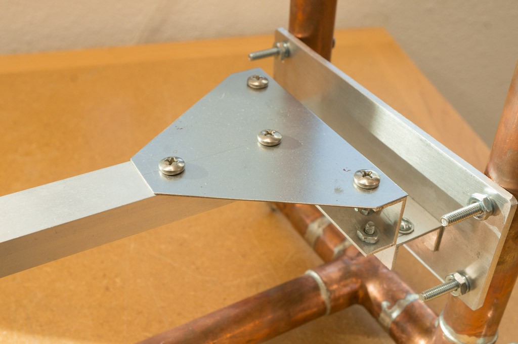
 My drawing software can't make fractional dimensions. The 0.87" translates to 7/8", 0.57" is 9/16" and 0.31" is 5/16".
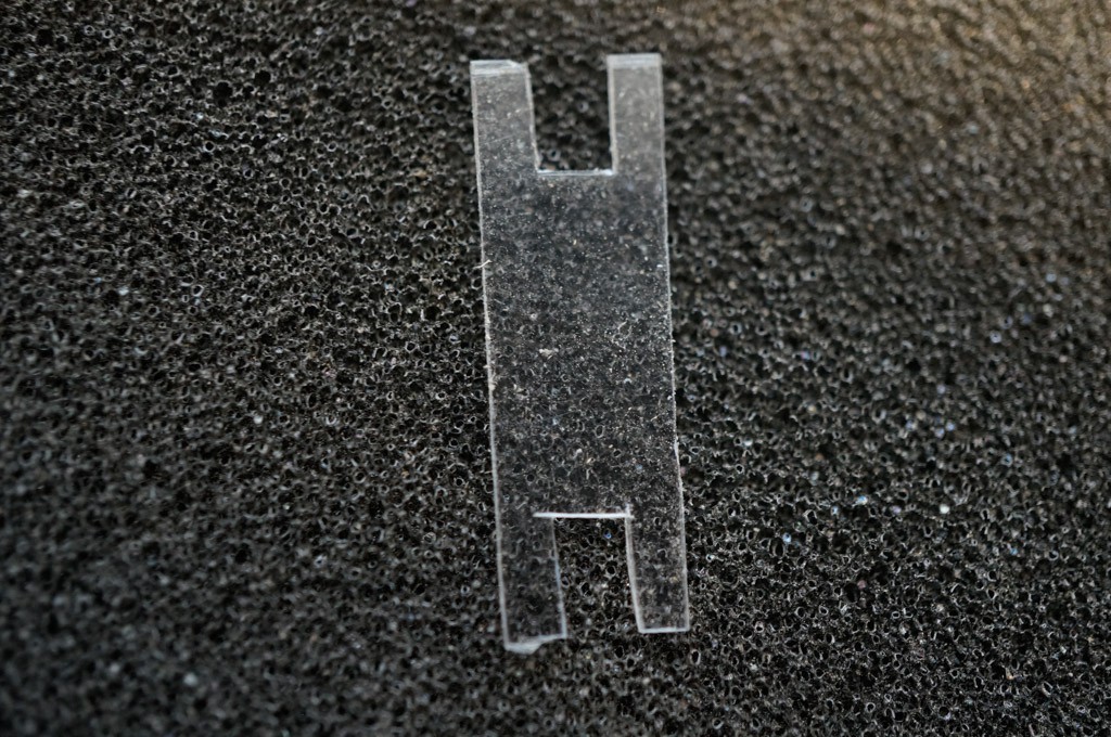

Discussions
Become a Hackaday.io Member
Create an account to leave a comment. Already have an account? Log In.