 Dmitriy
-
1Step 1
Choosing the platform and components. Preaparing tools.
I wasn't hesitating while choosing the platform I will use - definetely it's APM. The most important for me is that it has huge community and it gives a choice of hardware and software. The other significant thing - APM is an open source project and this can really expand future application of my drone.
After reading this article I've started looking through forums and tutorials searching the components with the best quality-price ratio. So for the very first manual take off I'll need:
1. Flight controller. (200 + 35 +7= 242$)
For flight control I'll use Raspberry Pi 2 and Emlids Navio2. To get started easily there is all neccessery docs on the Emlid website. In addition you'll need wi-fi dongle for Rpi2, it will cost 7-10 more bucks.
2. Copter frame (quad in my case) (11$)
I will be using FPV250 frame just because I got it for free from my friend. Moreover I was told that this frame will be enough for the first build and learn.
3. 4 motors with 4 electronic speed controllers. (24 + 36 = 60$)
For my 250 mm frame I've chosen RCX 1804-2400 motors with Emax Simon 12A Electronics speed control modules. To say the truth here I've just made internet search for motors and ESCs suitable for my frame, but here is very good article for choosing motors. ESCs are installed between motors and flight controller and are responsible for spinning speed of motors depending on requested speed from Radio control or autopilot.
4. Radio Control (RC): Transmitter and receiver (min. 6 channels). (60 + 73 = 133$)
Here I was guided by this tutorial. I prefer to learn flying in Mode 2, I will aquire budget Turnigy 9X (see in the list of components) and 2.4 GHz RC module and receiver. If you are going to use Navio2 in your build make sure you will use receiver with the support of PPM/SBUS.
5. Li-po battery and charger, Li-po checker (9 + 25 + 2 = 36$)
After reading introduction to Li-Po batteries I have ordered for my copter Li-Po battery with capacity of 1500mAh with 3 Cells. In addition I've got Li-po battery charger and voltage checker. Make sure you've read carefully the article provided here about Li-Po, it is very important to follow all the instructions while working with such batteries.
6. Propellers (4$)
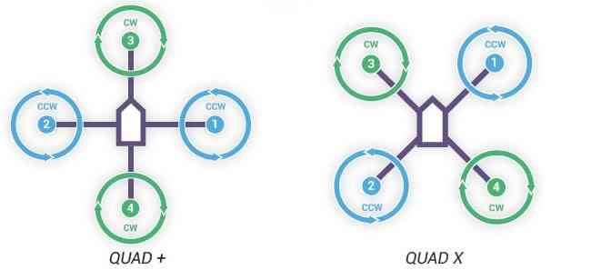
For choosing the right propellers I've observed for different projects and flying videos of my frame+motors combination. It seems like the only best option for 250mm frame are plastic 5030 propellers. A quadcopter uses two clockwise(CW) and two counter-clockwise(CCW) propellers. Propellers are classified by length and pitch. So if I am using 5030 propellers that means that they are 5 inch long and has a pitch of 3. Chosen propellers are rather fragile so you better buy few sets.
7. Power Module (16$)
To power all systems onboard of my quad I will need power module. It is providing a stable voltage (5.3V) and power supply of 2.25 Amp, this helps reduce the risk of electronics combustion. Moreover with power module we can monitor the battery capacity. Make sure you are ordering Power module with Df13 6Pin connector to provide connection of power module with autopilot.
8. Power Distribution board (6$)
You will need it to power ESCs (consequently motors) from power module.
9. Choose Ground Control Station (read first)
In few words GCS is a software which will be connected with your drone via telemetry and show you all data. With the GCS you will be able to change settings and configure all parts of your drone. I will use Mission Planner on my Windows 10. QGroundControl is also good.
10. Connectors and cable ties, some tape, damping balls (~15$)
You can find links to needed connectors and ties in the list of materials.
As I understood from Ardupilot wiki, later I will need the following components for using the capabilities of autopilot:
11. GPS-antenna (12$)
12. Telemetry Radio
Needed tools.
It will be great if you'll have access to a Fab Lab or any Maker Space while building your drone. You'll definetely will need:
1. 3d-printer.
To print anti-vibration mount for Rpi2 and case for Navio2
2. Hand tools like screwdrivers, etc.
To make a sturdy assembly.
-
2Step 2
Preparing Raspberry Pi with Navio 2.
While waiting for all the components to arrive I was playing with my Rpi2 and Navio 2. I won't copy here docs and instructions from here and here, I just recommend you to reproduce getting started and example steps from these resources.
I won't waste time and fill this section with detailed tutorial with pics because other people already did this very well.
To prepare you flight controller you should do the following:
- Burn SD card for Raspberry Pi with latest Emlid software from here: https://docs.emlid.com/navio2/Navio-APM/configuring-raspberry-pi/
I recommend to use Etcher utility. Before installing SD card in Raspberry Pi, make sure you've changed "wpa_supplicant.conf" where you specified your Wi-fi SSID and Password.
- Attach Raspberry to Navio2 according to the manual. Check twice that Navio2 is installed tightly, because that's the reason of having a lot of issues while configuring autopilot. Install SD card. Attach Wifi dongle if you're using RPi 2.
- Power Rpi with USB-cable. I am powering my board from laptop usb port.
- Install Nmap and Putty to login to Raspberry Pi. In NMap type "navio" and make search to find your RPi IP adress. Type found IP in Putty and connect via SSH to Rpi. Login is "pi", password is "raspberry".
-
3Step 3
Running Ardupilot and make it start automatically.
First we should download Ardupilot. After you logged in navio type:
sudo apt-get update && sudo apt-get install apm-navio2This will install ardupilot. Be patient, it will take a while.Next thing we should do is to make ardupilot start automatically on boot. To successfully do this we should navigate to /etc/rc.local file on Raspberry pi:
cd ../..
cd etc/
Open it:
sudo nano rc.local
and in insert the following in this file:
sudo nohup ArduCopter-quad -A udp:192.168.1.25:14550 -C /dev/ttyAMA0 > /home/pi/startup_log &
where IP adress is an IP of your laptop with ground control station. To learn your IP open command line in Windows and type "ipconfig".
In the end you should save and exit file using CTRL+X. Press Yes to save changes. After all this reboot your Rpi. After it will be reloaded an LED on Navio should be blinking.
NOTE: Don't start examples while ardupilot is running. You will get incorrect data.
-
4Step 4
![]()
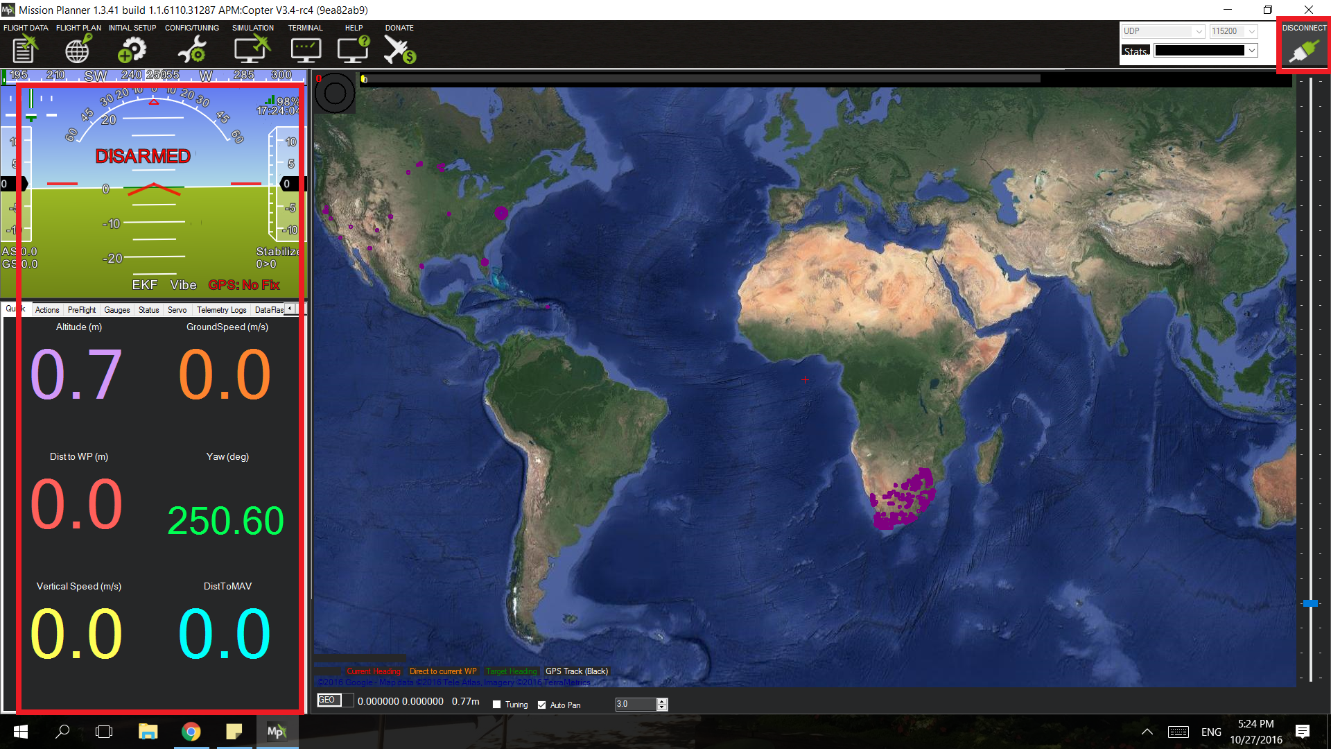
Connecting Ground Control Station.
So when LED on Navio2 is blinking that means ardupilot launched. You can start Mission Planner on your laptop and press "Connect" in upper right corner. When it will ask you about port, specify that it is 14550.
Then you can move your Navio2 and see how the orientation is changing in Mission Planner.
In this tutorial we will use Mission Planner only for Calibration of our drone.
-
5Step 5
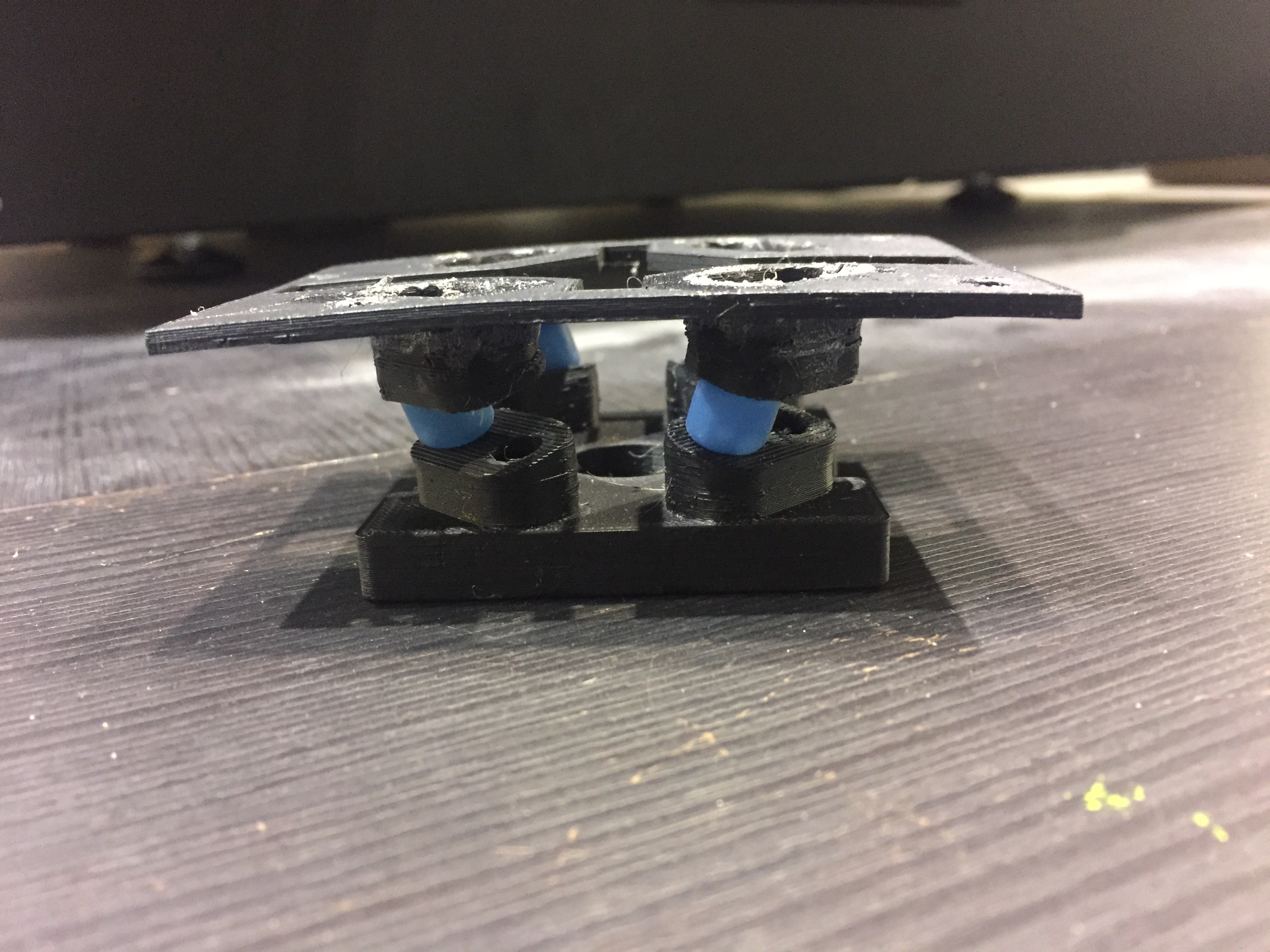
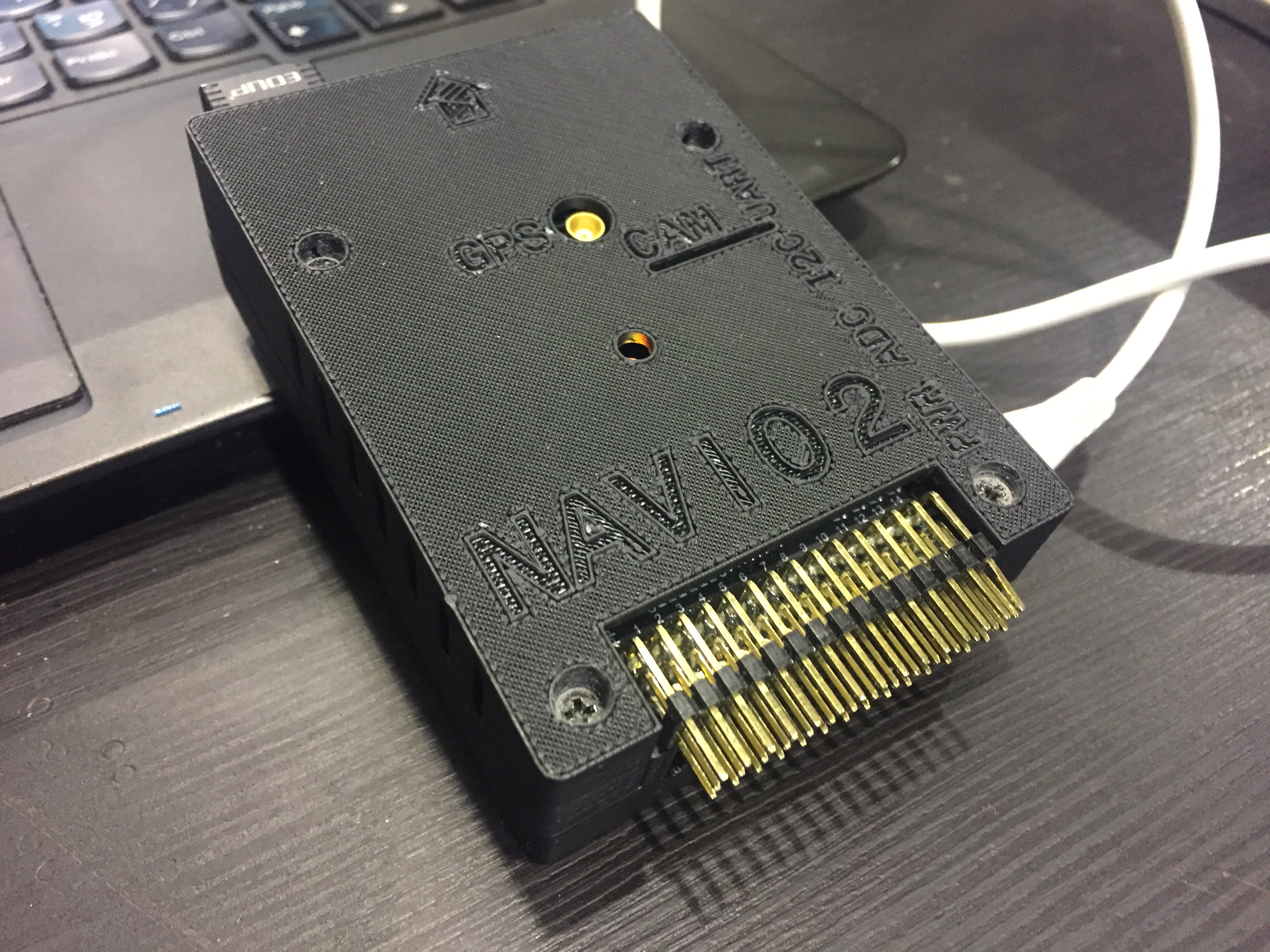
3d printing of the case and anti-vibration mount.
I should say that Emlid has an anti-vibration mount model only for 450mm frame. In my case I had to redesign it for 250mm. 3d model for case I've taken from here. Within the project I've attached files for printing. I've used Zortrax M200 and Maker Bot Replicator 1 for parallel printing of my parts. I love the result.
![]()
![]()
Using 4 small screws I fix these 2 parts together. The flight controller is ready for mounting on frame!
-
6Step 6
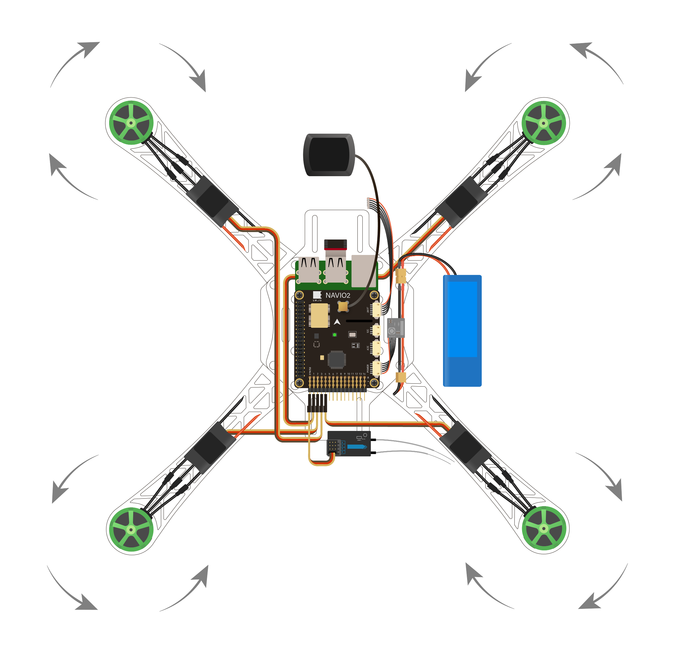
Frame assembly and NAVIO2 pin connect.
After I've got all the components in my hands, I started copter assemling. I was using mostly using video tutorials. I will leave links here and I hope that they will worked for you, as they worked for me.
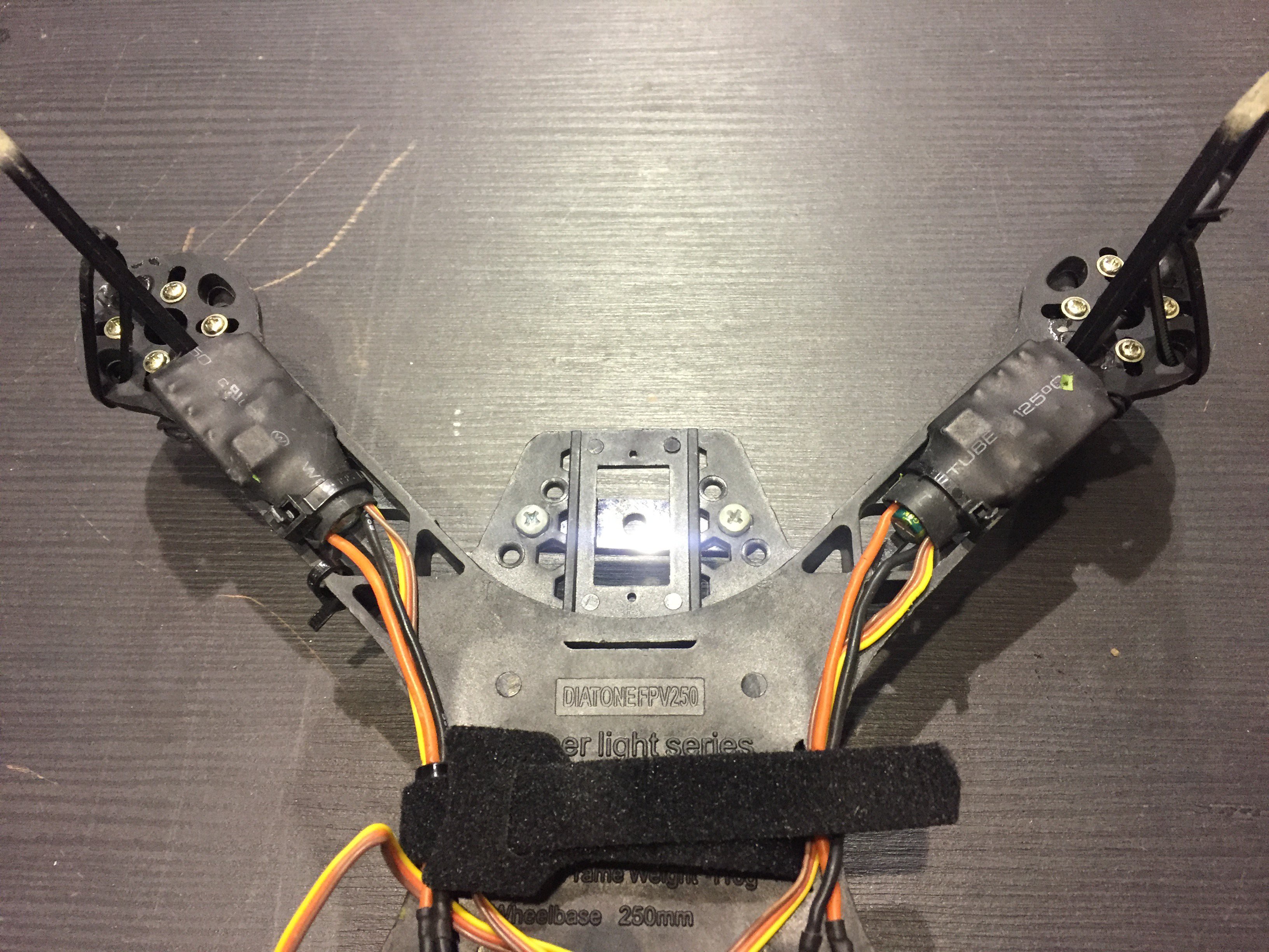
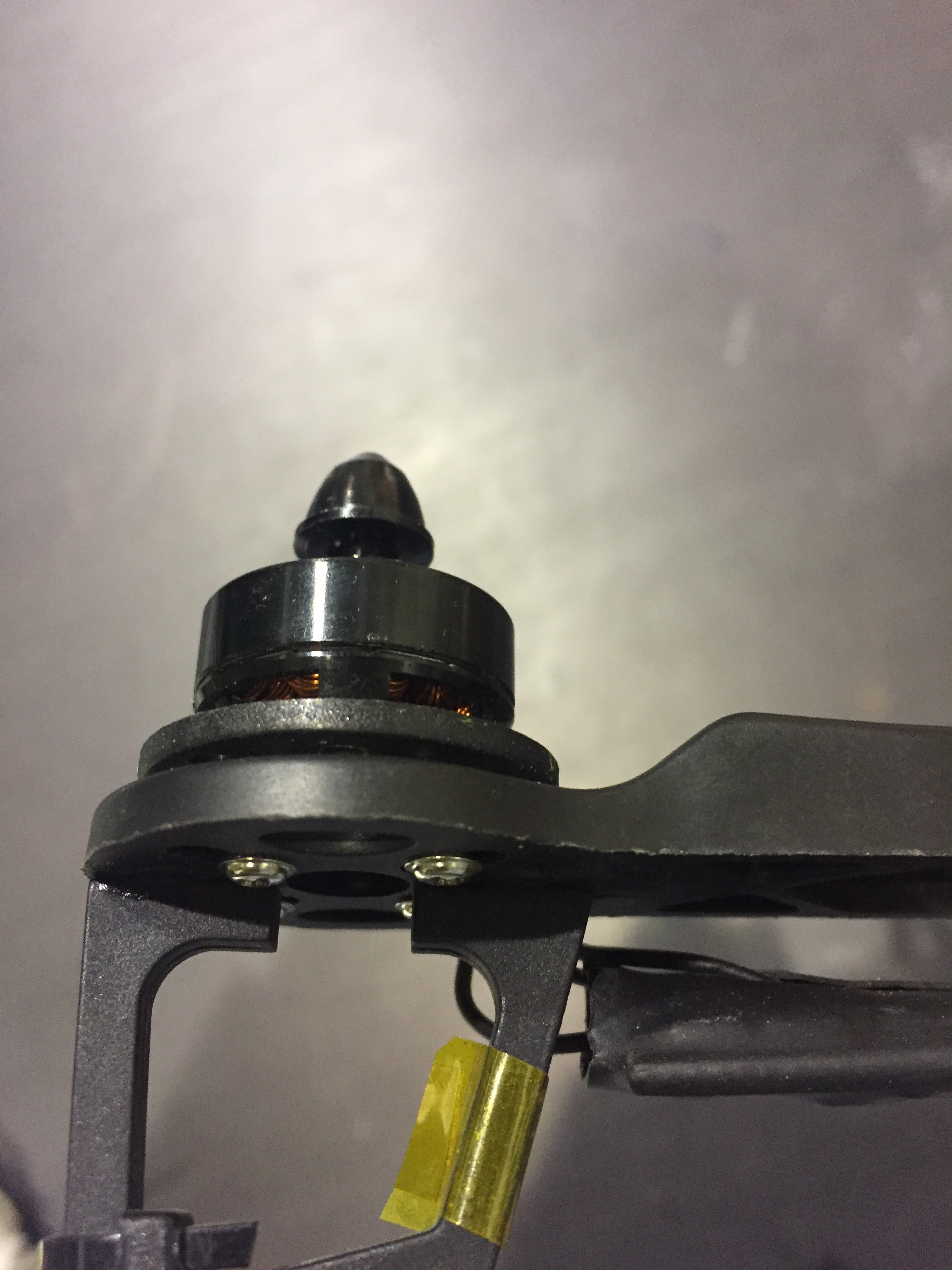
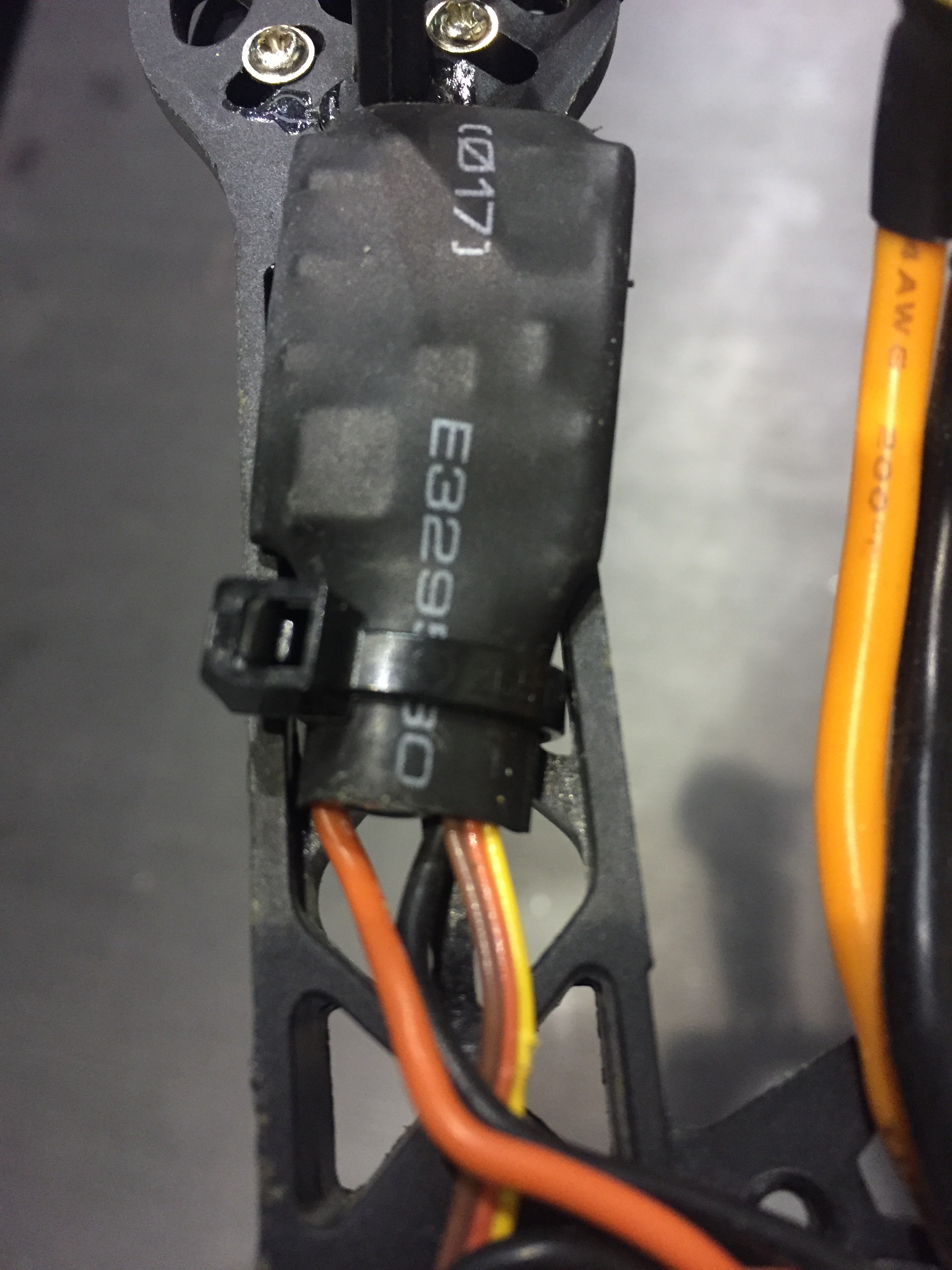
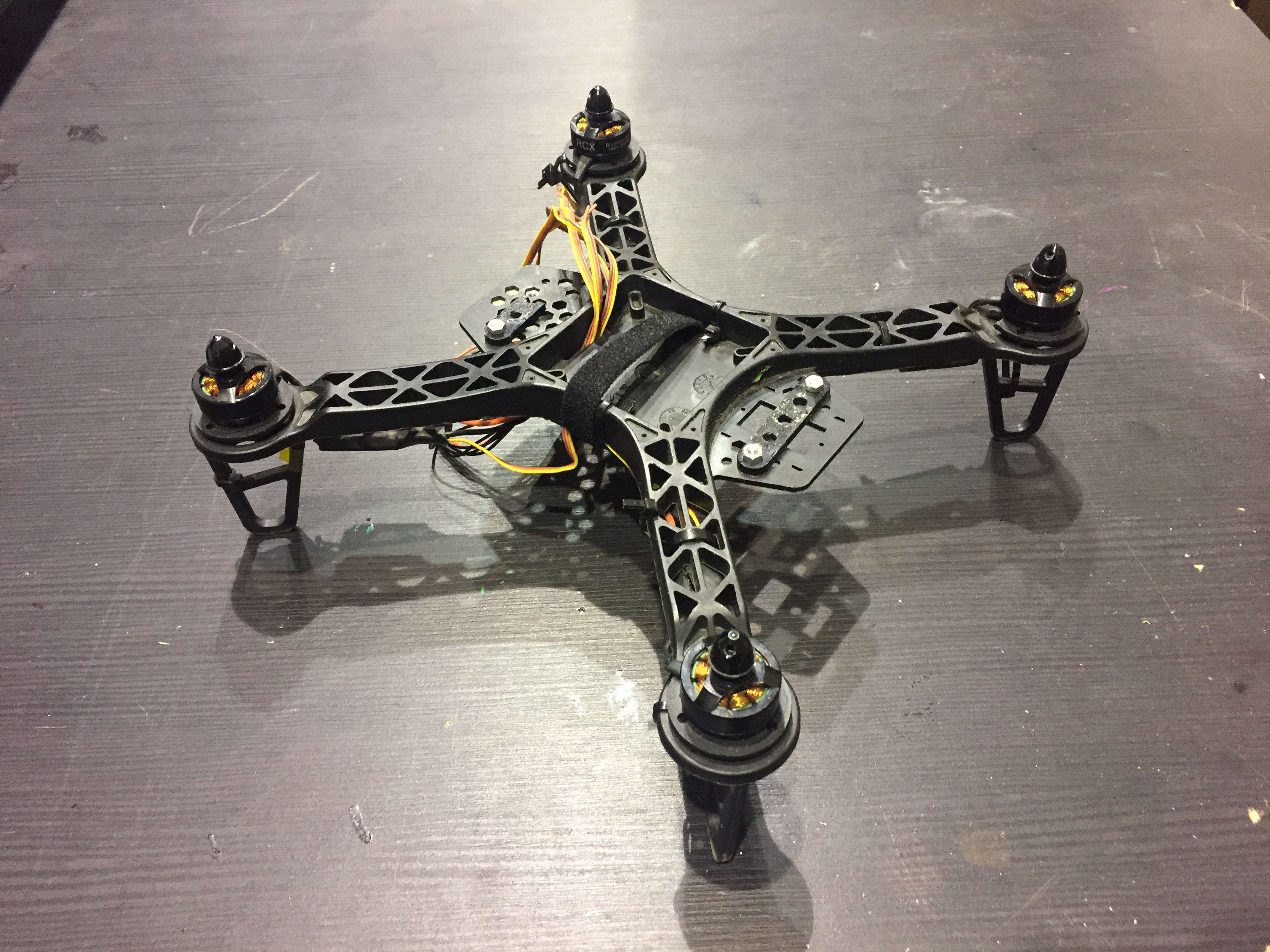
1. Install motors and ESCs and fix them on frame. Attach wiring using cable ties.
![]()
![]()
![]()
![]()
2. Connect ESCs to Power Distribution board (PDB). Attach powermodule. Good video is here:
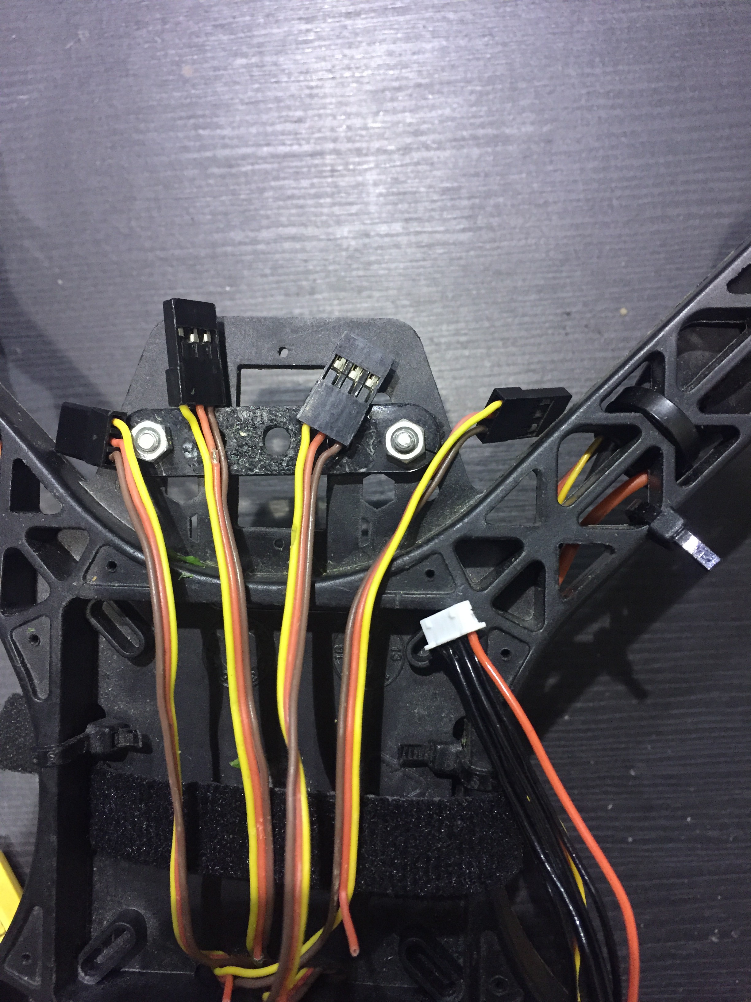
3. Take into consideration that only one ESC power wire (central) should be connected to Navio2 servo rail, otherwise BECs built in ESCs will heat each other. So you have 4 ESCs and only 1 ESC central wire should be connected.
![]()
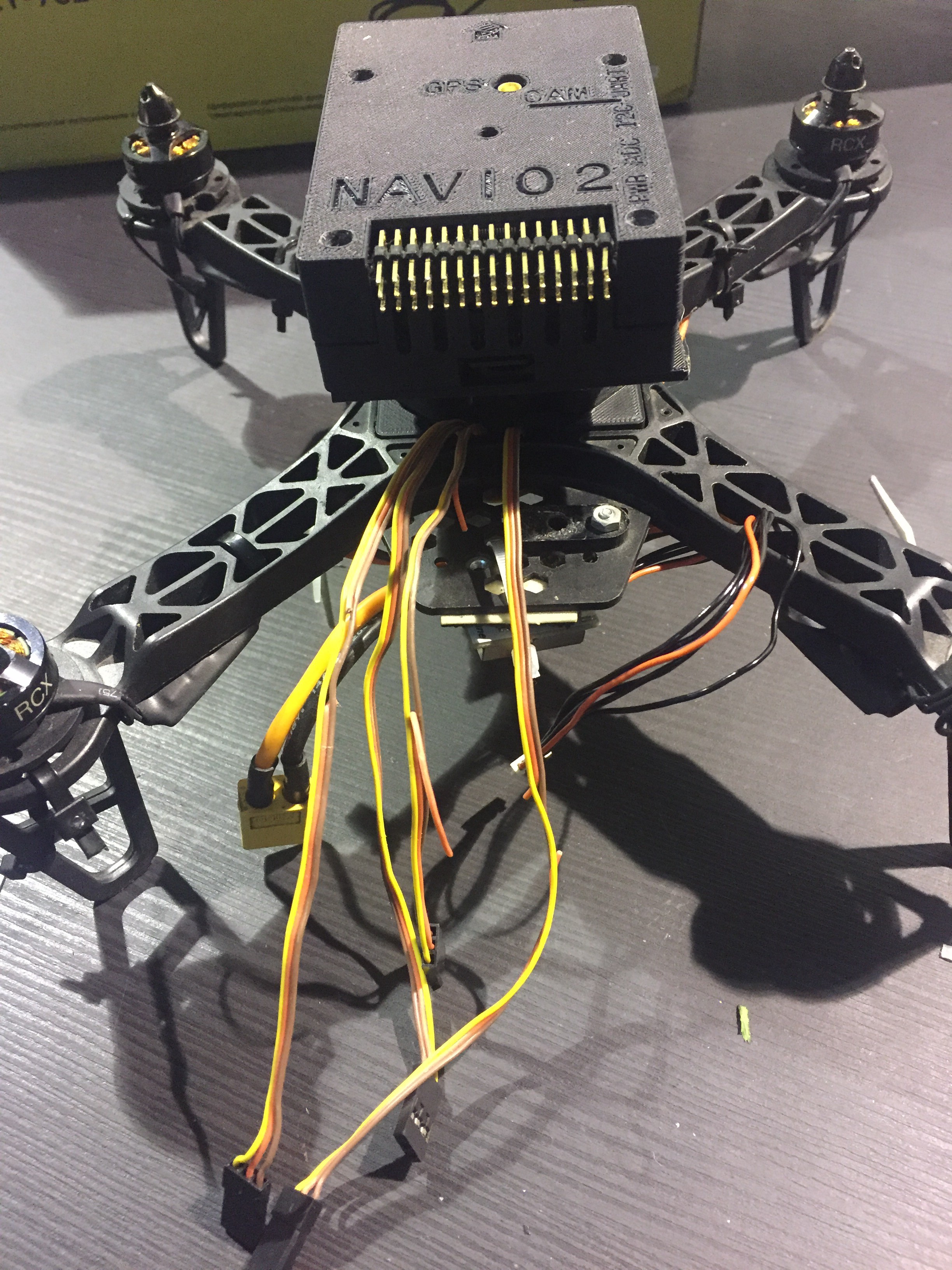
4. Install Anti-vibration mount with Navio2 in the case on top on the frame. Bottom part of the anti-vibration mount is designed to fit tightly in the slot of 250mm frame. Make sure you install Raspberry Pi and NAVIO2 in right direction.
![]()
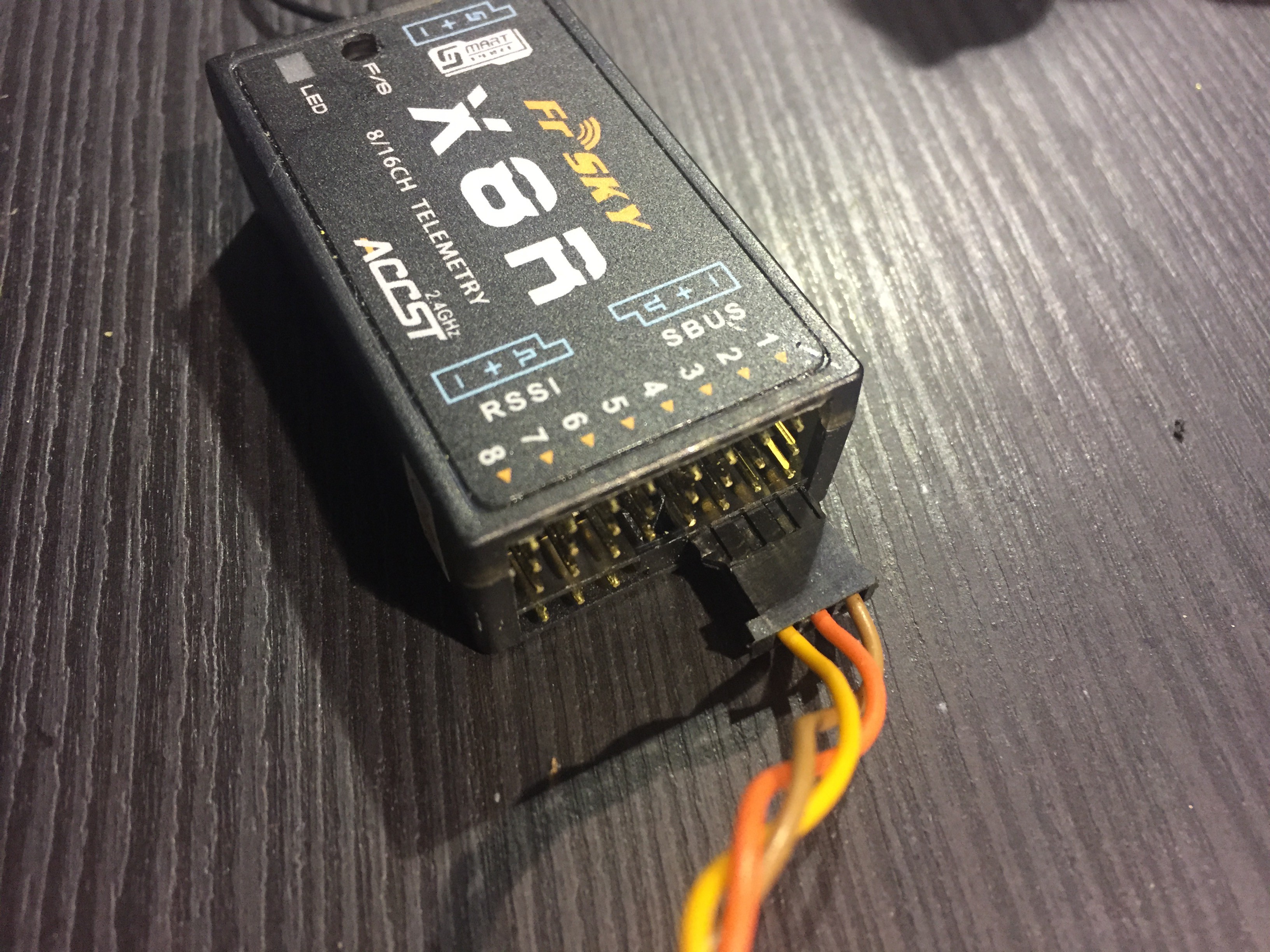
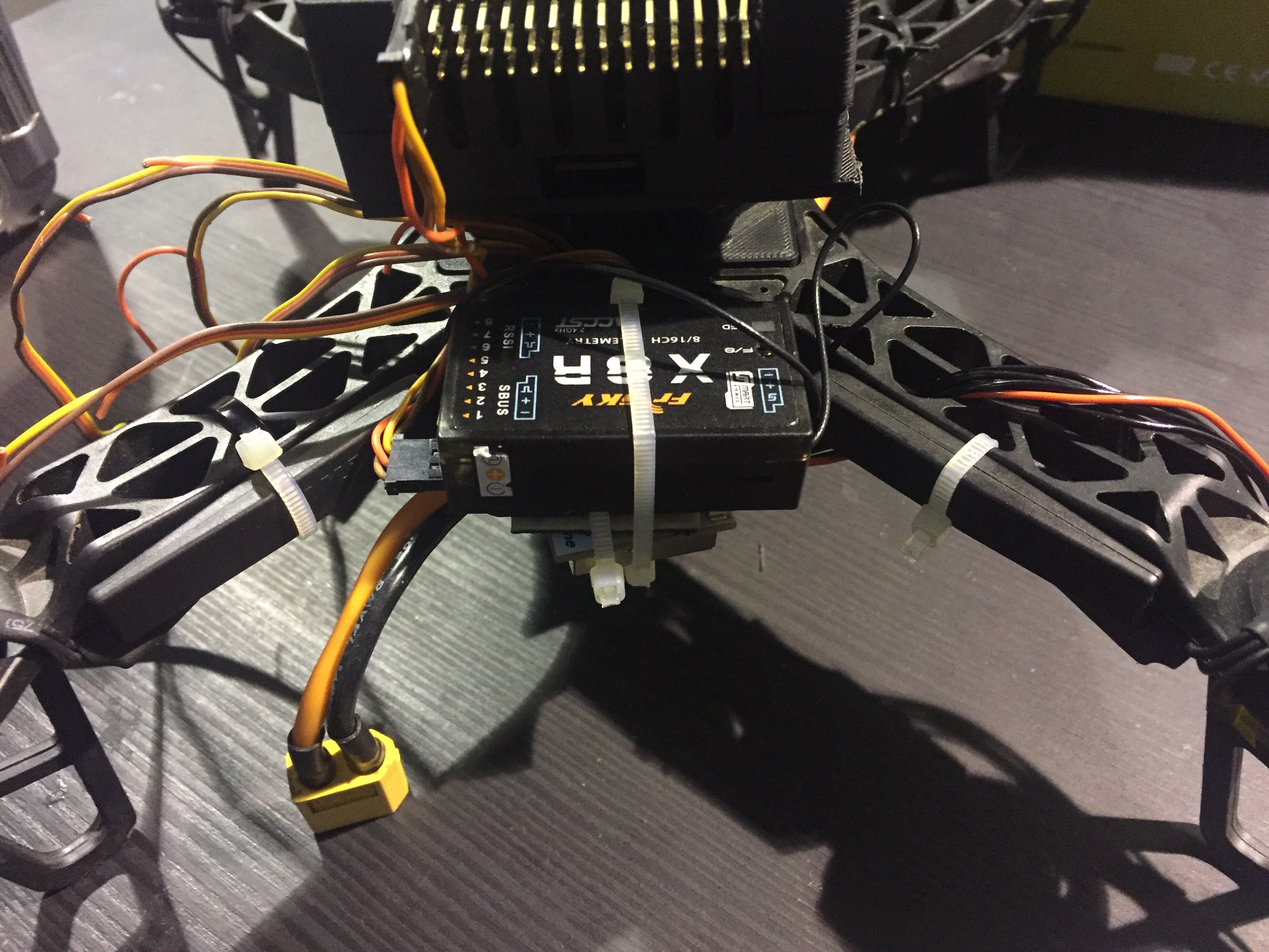
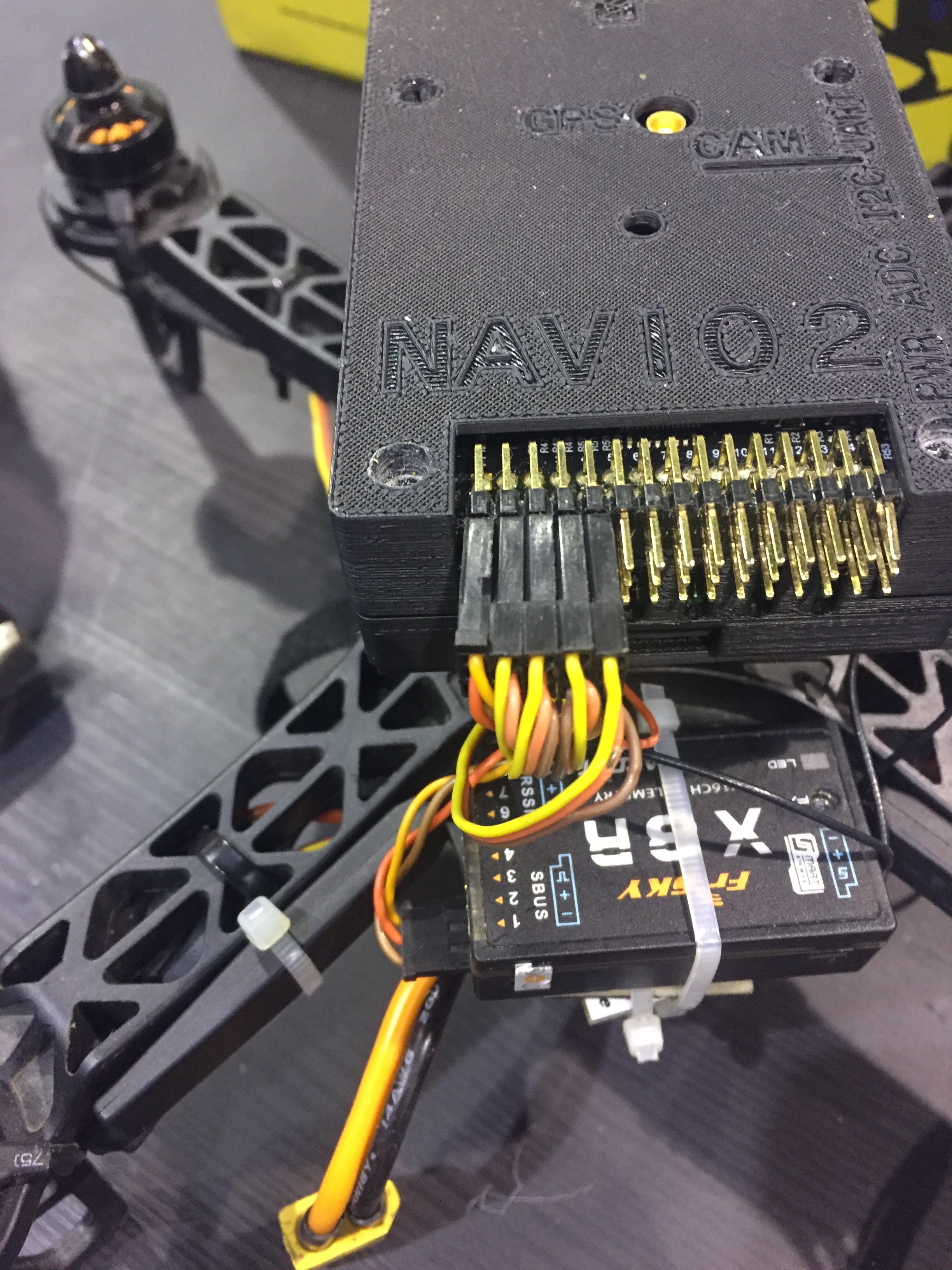
5. Install RC receiver on frame and connect it to NAVIO2.
![]()
![]()
6. Connect 6-pin DF13 cable from power module to NAVIO2.
![]()
7. On the next step we will connect motors to NAVIO2 (next step of instructions).
-
7Step 7
Connect motors to NAVIO2.
![]()
![]()
![]()
Connect carefully 3-pin cables from ESCs to NAVIO2 according to schemes from docs.emlid or ardupilot.org.
-
8Step 8
Charging and attaching the Li-Po battery.
Check this really good tutorial for Li-Po batteries and instruction for you Li-Pi charger once again. Always check battery with Li-Po checker.
-
9Step 9
Radio module and receiver bind.
I am using transmitter with second mode and XJT module. To understand how to bind it with X8R receiver refer to this video.
My own experience is here:
-
10Step 10
Radio Control Calibration.
When assembly is almost done and RC and TX are bound it is time to calibrate autopilot.
1. Power Raspberry Pi from USB port.
2. Make sure your ardupilot will start automatically. LED on top of NAVIO2 should start blinking.
3. Make sure it will send telemetry to your laptop. If you haven't done this yet- refer to previous steps of this instructions. It won't take a lot of time
4. Launch Mission Planner (or preferable GCS)
5. Check that Transmitter is working and X8R LED is green. (NOTE: Connection between RX and TX might be bad if they are too close to each other).
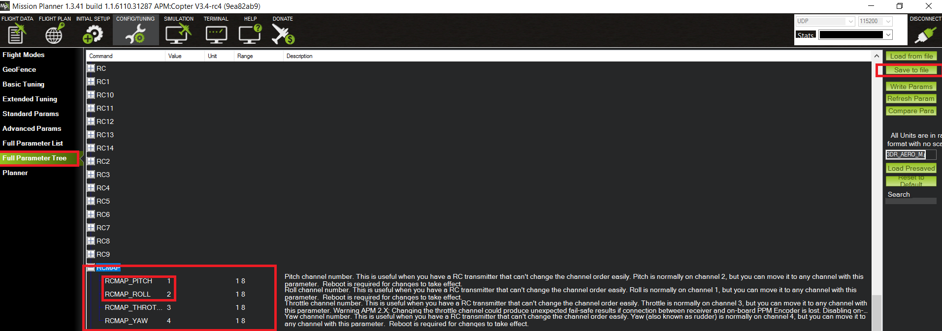
6. Go to Initial Setup -> Mandatory hardware-> Radio Calibration
Here will be very useful this article. I was calibrating my Mode 2 transmitter and had problem with Roll/Pitch inversion. It turned out that JR PCM9x transmitter, I was using before Turnigy 9x has arrived, has different preconfigured modes. To manually change channels go to Config/Tuning -> Full Parameter Tree -> RCMAP. After making changes it is important to Write Params to save settings.
![]()
My first copter build with RPi2 and Emlid Navio2
Focused on making clear every building step with helpful links and tips for total noobs (like me) who wants to get started with drones

Discussions
Become a Hackaday.io Member
Create an account to leave a comment. Already have an account? Log In.