 Emily Velasco
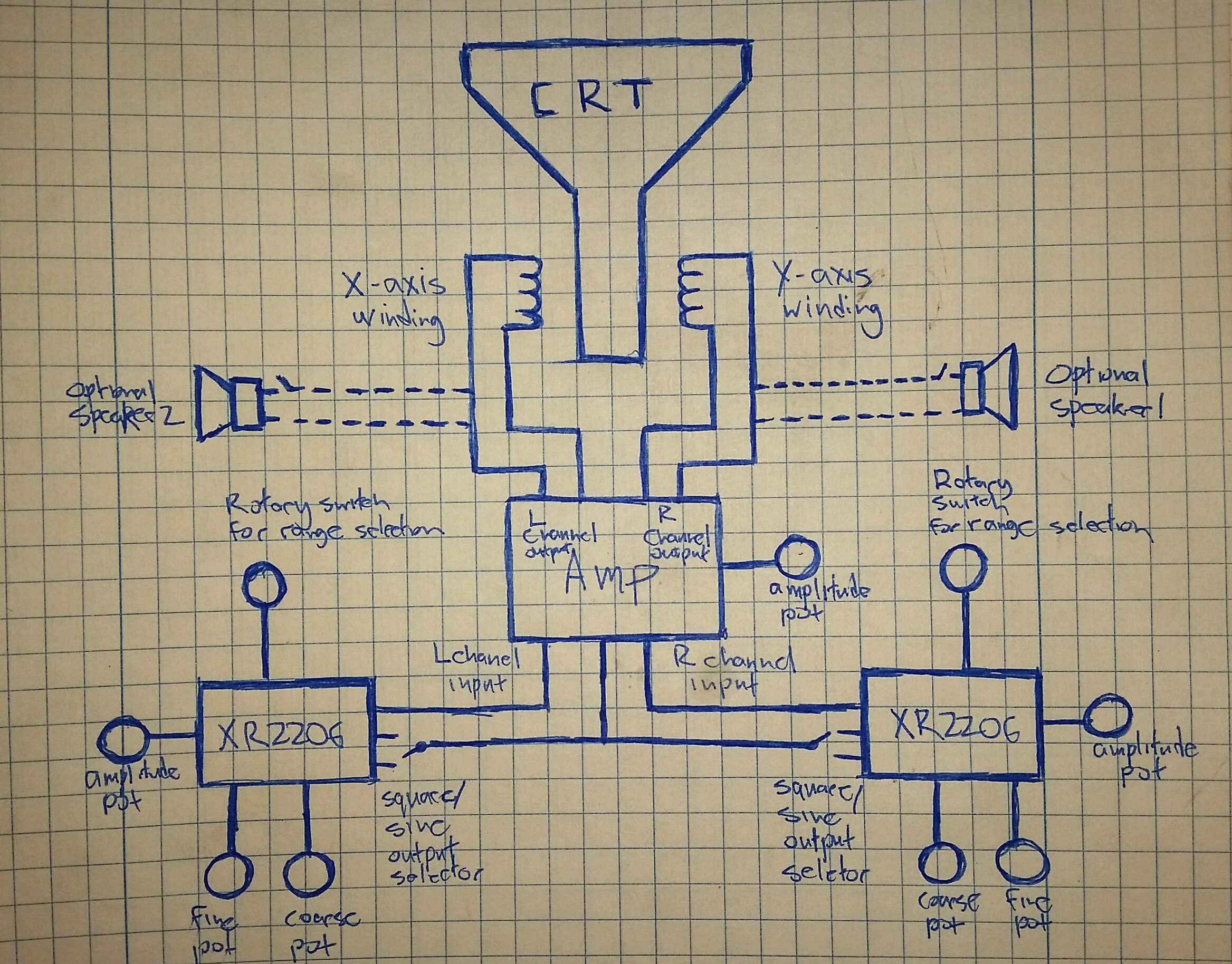
A block diagram showing how all this is going together
This is my attempt to build a device that will trace Lissajous curves on a CRT with input from the user.
Already have an account? Log in.
To make the experience fit your profile, pick a username and tell us what interests you.
A block diagram showing how all this is going together
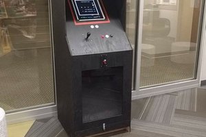
This week has been spent on making the front panel for the Lisssajous machine. Since it's going to be the part of the machine the user interacts with, I wanted it to be nice, and since it needs to house the screen, as well as 15 knobs and switches, I decided to take the time to do it right.
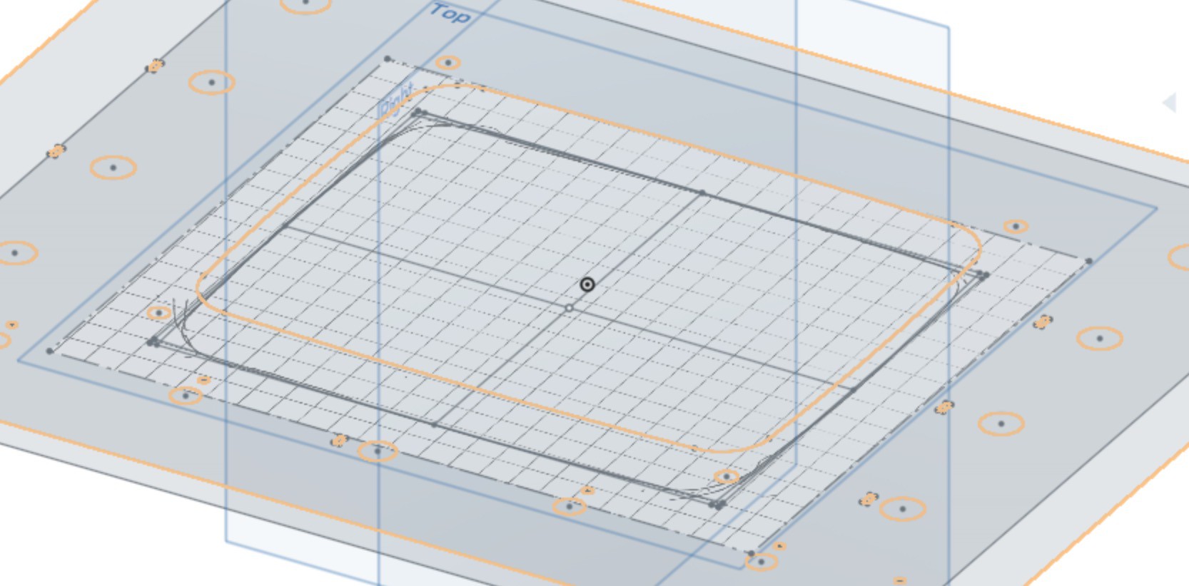
To get started, I traced an outline of the CRT screen onto some graph paper, and then scanned the tracing and uploaded it to Onshape, the free online CAD software I used for most of my CAD work.
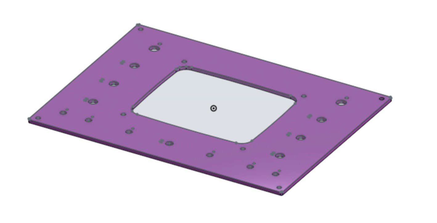
With the tracing in Onshape, it was easy to create a panel with an opening that would fit the CRT. Doing this in CAD software also gave me the option to try several arrangements of knobs before settling on what I wanted.
I had originally planned to make this panel out of transparent red acrylic, and friend of mine had a bunch of quarter-inch acrylic sheets in several colors that he was happy to share with me. But when I asked about using some for this project, he let me know that he had gotten rid of all of the acrylic :/
I started looking around for quarter-inch transparent red acrylic, but the prices were all higher than seemed reasonable to me. Another friend of mine said he had had some lucky dyeing plexiglass by boiling it in a solution of Rit clothing dye. I had some scraps of plexi lying around at home, and Rit is only $2.50 a box so gave it a try.
Did it work? No. It worked just a little bit on Lexan, but there was no discernible color change in the plexi. Someone on Twitter suggested I could try adding a some isopropyl alcohol to the dye bath, so I did, but that didn't really help.
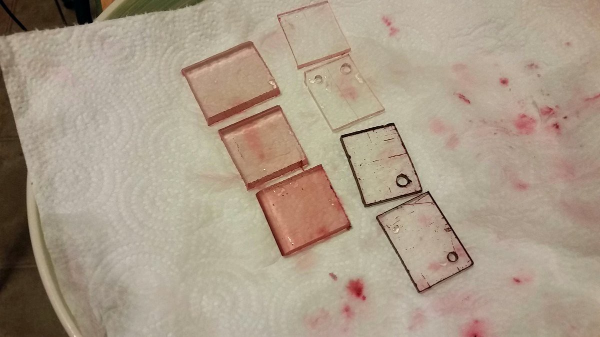
The lexan pieces are on the left. From top to bottom: 35 mins, 45 mins, 55 mins with ten mins after alcohol addition. Plexi is on the right, top to bottom: 35 mins, 45 mins, 55 mins with ten mins after alcohol addition, 65 mins with 20 mins after alcohol addition.
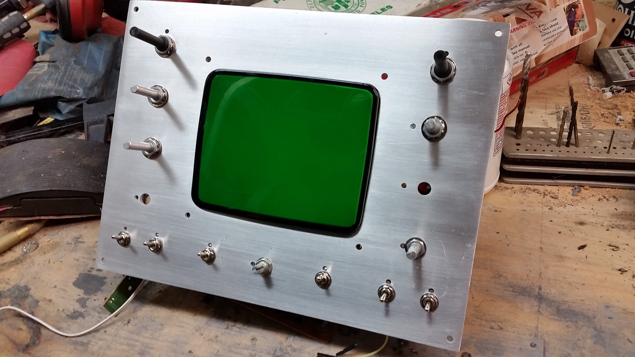
Ok, plan B for the front panel is aluminum. I'm lucky to live near a good scrap yard with lots of interesting stuff to pick through and decent prices. I got down there on a rainy morning before Sparklecon and picked up some stuff, including a sheet of aluminum that would work for this project.
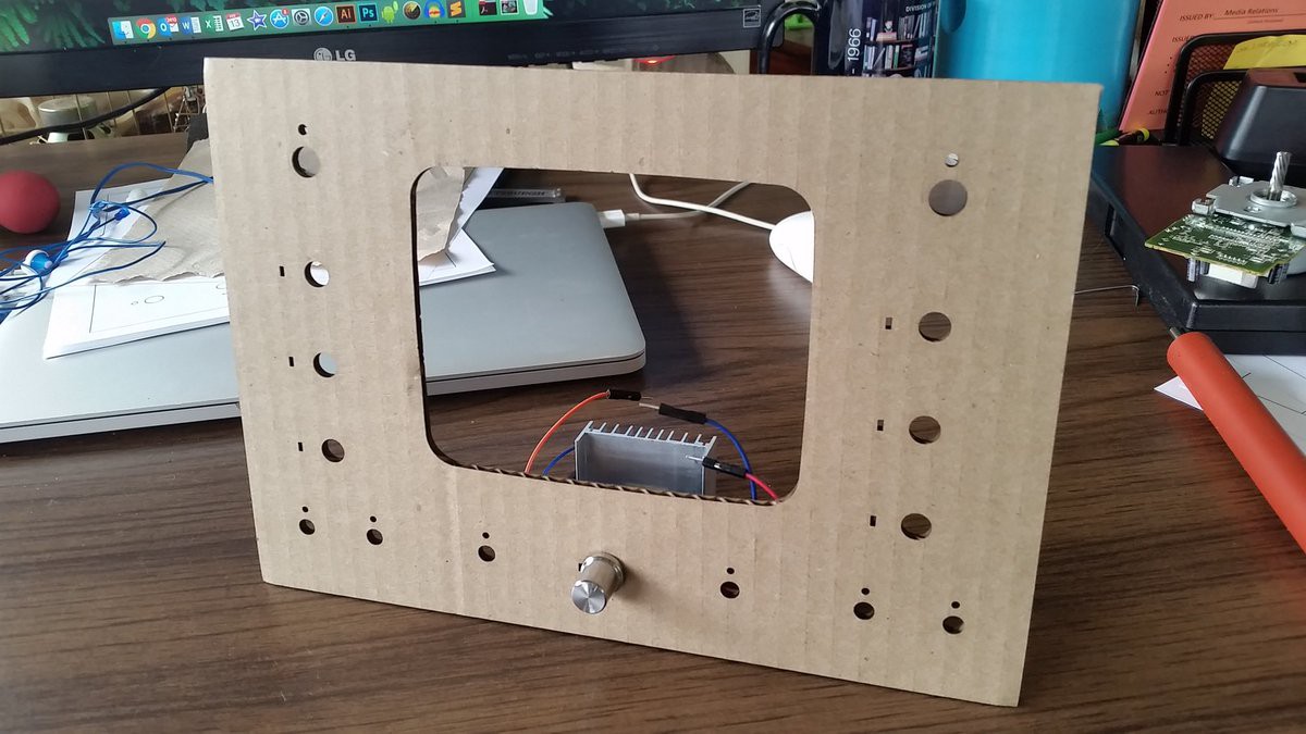
I'm also lucky to work at a place that has a machine shop that I'm allowed to use. I got down there this week first laser cut a cardboard mockup of the panel just to make sure things would fit right.
Things fit pretty nicely, so I made a few minor tweaks, and then got back down to the shop on Friday to use the water jet cutter.
The panel, being made of a piece of scrap from the junk yard was scratched, pitted and oxidized, so I spent Friday night cleaning it up. A rough sand with the random-orbit sander cleaned up most of it, but left some squiggly scratches. I put the whole thing in a bath of concentrated lye for a while to etch everything down a bit. It gave the panel a nice satin finish.
I spent the rest of the night sanding, brushing, and polishing the panel, and it looks great!
Next up, the wood parts of the case.
Between Sparklecon, and some other things that have come up, I haven't had much time to do much work on the hardware for for the Lissajukebox lately. I have gotten some work done on the case, but nothing to show off yet.
In the meantime, here's a little background on Lissajous figures.
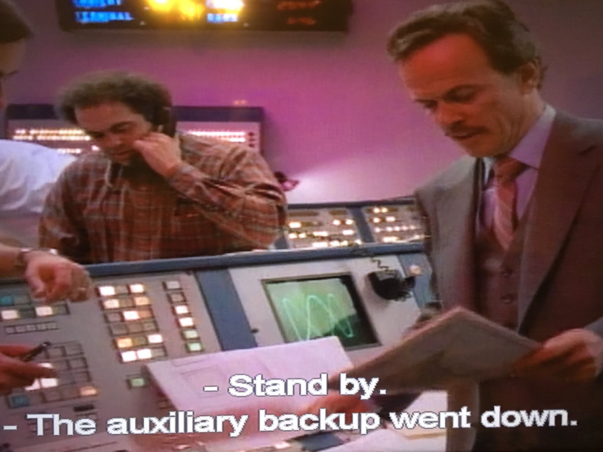
If you've seen a Lissajous figure anywhere, it's probably somewhere in the background of a TV show. Sometimes they get trotted out to make a computer monitor look like it's doing something important and high-tech.
Here's one the appeared in an episode of MacGyver.
An especially prominent example appears in the intro to the original Outer Limits
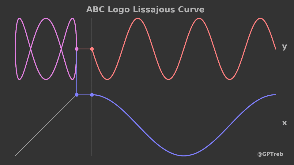
Ok, but what's really going on with Lissajous figures besides looking neat? I could try to explain them, but I think a couple of gifs will explain it better.
I don't know who the creator of this really excellent one is. If anyone does, please let me know and I'll provide credit. It's nice because it clearly shows how ratios create the many different Lissajous figures that are possible.
And here's another good one created by Grant Trebbin.
More progress coming soon!
Let's talk about the XR2206 function generator. First, some brief background, then how I'm using them in this build, and lastly, the modifications I'm making.
Background
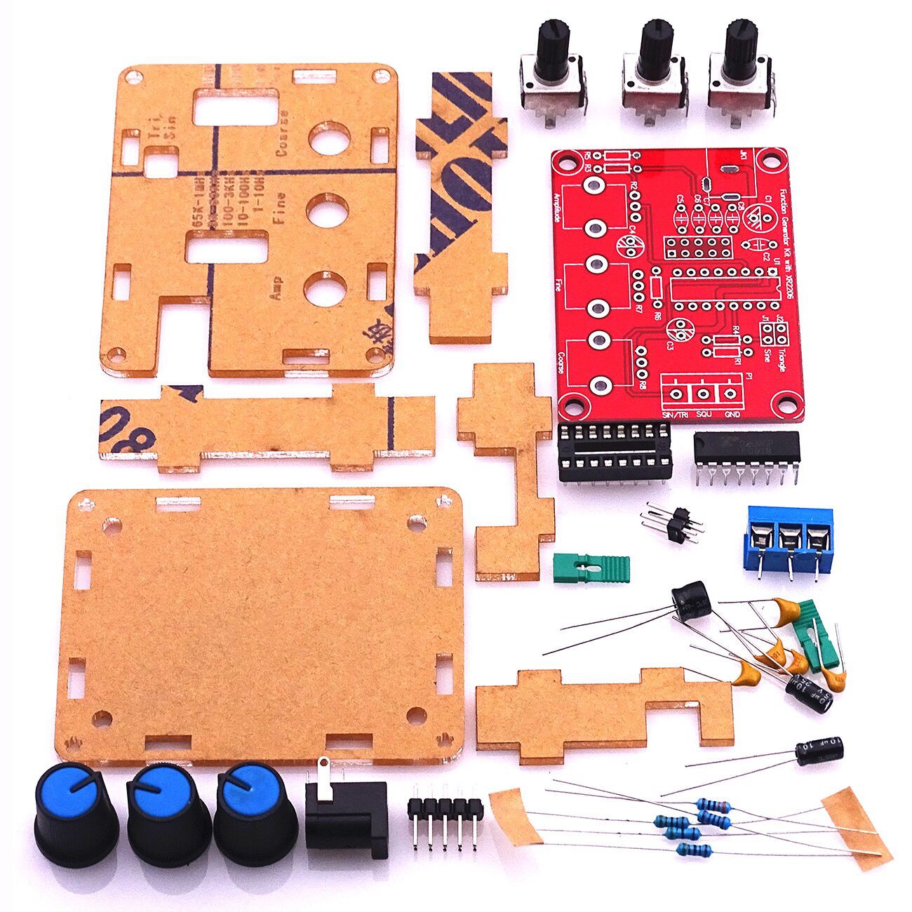
The XR2206 is, according to its manufacturer, Exar, a "monolithic function generator integrated circuit capable of producing high quality sine, square, triangle, ramp, and pulse waveforms." From what I understand, the chip is considered obsolete, and is no longer made by Exar. However, knock-off versions are still manufactured in abundance by factories in China, and its these chips that serve as the heart of the XR2206 function generator kits that can be found on eBay, AliExpress, Banggood and elsewhere for a mere pittance ($6-$9 US dollars).
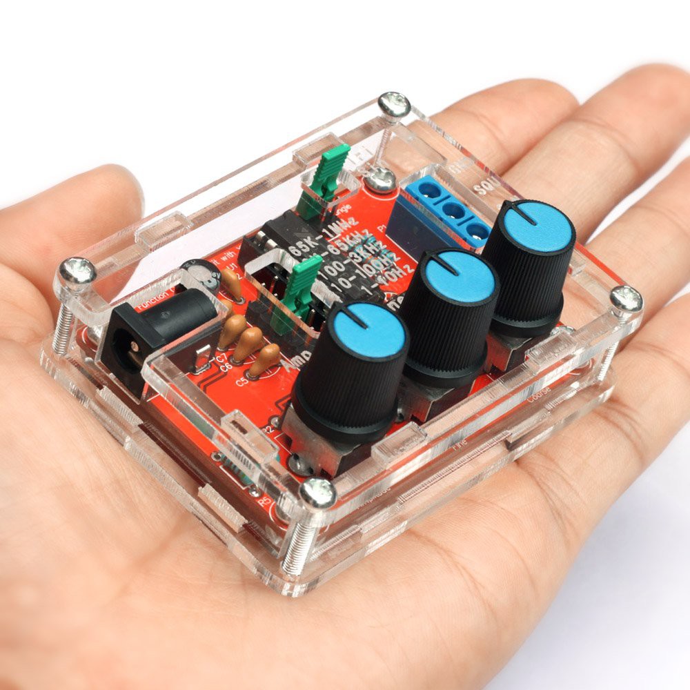
The kits are a quick, fun build, and make a useful, if not high quality, function generator that's good for hobbyists. They usually come bundled with a laser-cut acrylic case and, IMO, look pretty attractive when assembled.
How I'm using them
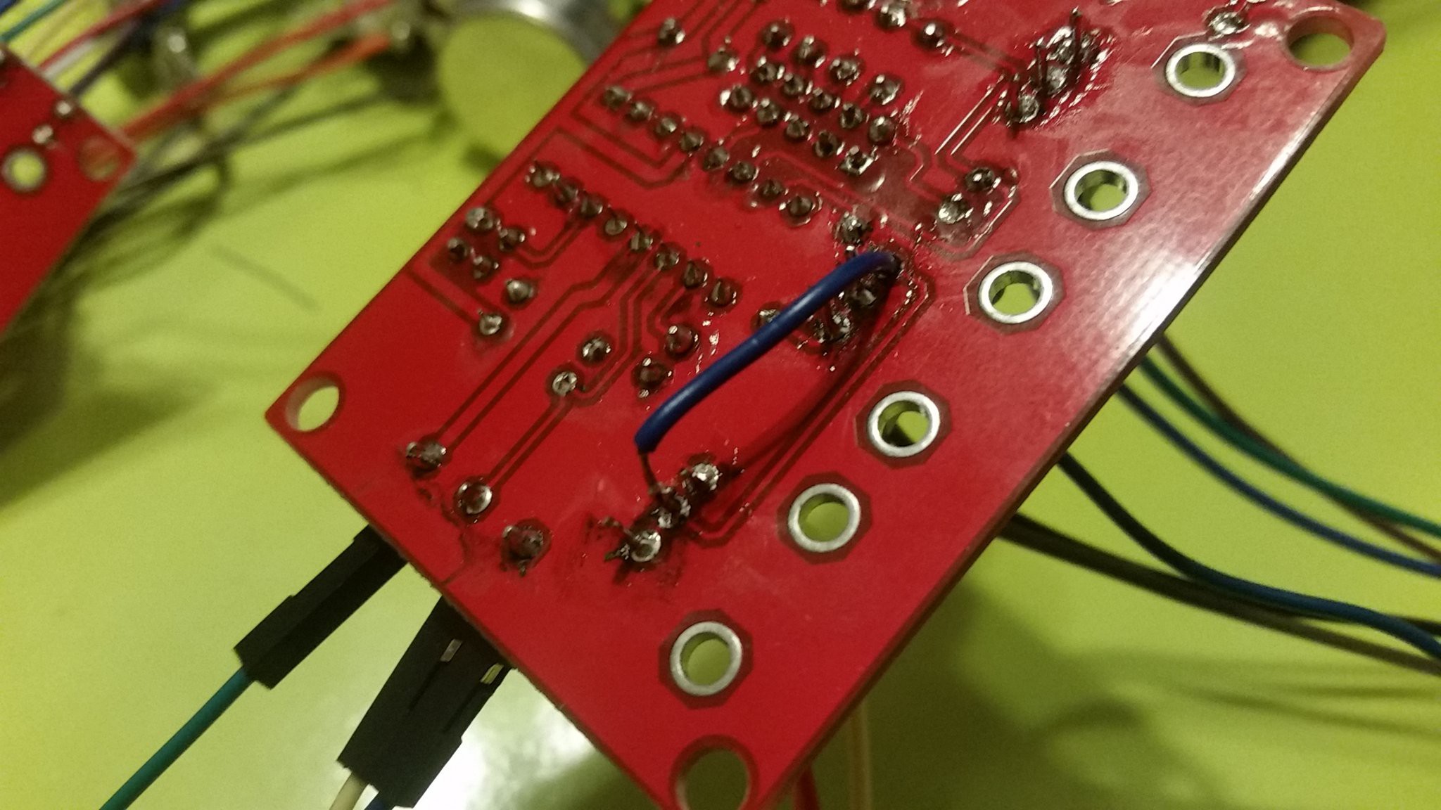
Since these kits are cheap, easy to build, and small, they seemed like the perfect way for me to supply variable waveforms for my project. Assembly went quick, maybe a half hour for each one, and everything went smoothly except for one screwup on my part that required me to bodge in a bridge wire after I overheated a via on the board.
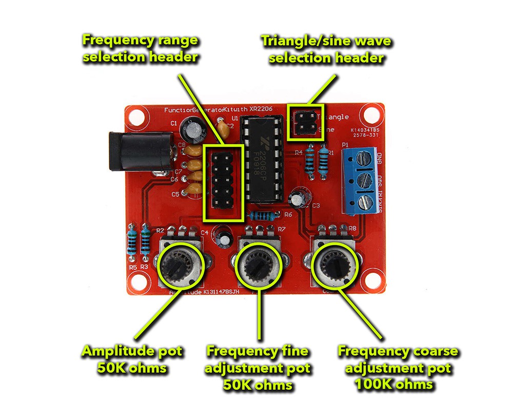
As nice as these kits are, they do have some features that limit their usefulness as the "brains" of a Lissajous console. These kits are going to serve as the main point of interaction between the console and the user. Each board has three potentiometers and two sets of headers that can be manipulated to created the desired waveform output. Here's an overview:
Because these kits are so inexpensive, the components used in them are really cheap. The potentiometers mount to the board through solder connections, and two tabs, and the headers use tiny plastic jumpers smaller than your pinky fingernail. These components work fine in kit form, but not as part of a console. The potentiometers do not provide a way to be panel mounted, and the jumpers are fiddly to manipulate and are apt to get immediately misplaced.
The modifications
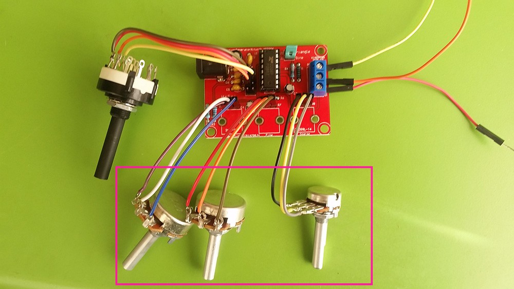
The first modification I made was replacing the stock potentiometers with more robust versions that can be panel mounted. While I was at it, I swapped in a 10K pot for fine adjustment because I found that the stock 50K pot wasn't well suited for making fine adjustments. I gave all the pots long leads so I would be able to place them where I want them in a front panel. It was at this step that I ended up needing that bodge wire. I wanted to make sure the kit worked before putting aftermarket pots in, so I soldered the stock pots in first. The kit worked, so I removed the stock pots. Unfortunately, one of the pots took a via with it when it came out. If I were going to do this again, I would solder in the long leads, and then solder the stock pots to them, instead of soldering them right to the board.
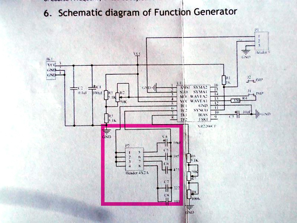
The next step was to do something about eliminating the header/jumper range selector combo. As you can see from the schematic, the frequency range is set by selecting one of five capacitors of various values.
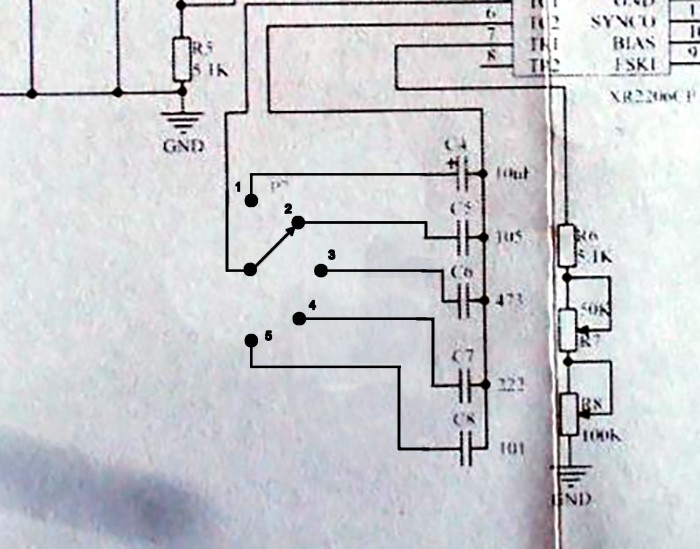
I contemplated using a patch cable and banana jacks (as found in synthesizers) but ultimately decided that a rotary switch would be easier for the user, more aesthetically pleasing, and importantly, cheaper for me to purchase. Here's how I wired it into the circuit:
And here it is attached to the board. As you can see, I left the original header on, and attached the switch to its contacts. I didn't actually connect all five capacitors to the switch, and that's for two reasons: 1.) The deflection coils of the CRT yoke don't respond much to the frequencies at the top or the bottom of the XR2206's range, so those range selections were kind of useless in this application. and 2.) Rotary switches are quite expensive,...
Read more »Black-and-white can be boring, but that's more or less what we're stuck with when working with small, inexpensive CRT monitors.
Monochrome monitors, like green or amber, have a special vintage charm, but their growing rarity makes it painful to tear them apart for a project.
For a while, I've been toying around with faking a green monochrome monitor using a black-and-white CRT and stained-glass spray paint. My first attempt was with purple paint, and it was a failure. I tried again, this time with green paint, and the results are quite good!
This paint is made by Krylon, and is available at some craft stores for about $10 a can.
Before applying, I made sure to thoroughly clean the surface of the CRT with alcohol. I then used masking tape to remove any bits of lint left behind by the paper towels. I found it helpful to have a box I could set over the top of the CRT in between coats to keep ambient dust from landing in the paint and sticking.
This is an optional step. A black-and-white display might suit some purposes better. Other colors of paint (other than purple) might work as well.
This project crystallized bit by bit. It started with a YouTube video, and a teardown of a TV, and snowballed from there.

I've got all the components for this except I am going to use a 4" flat CRT from a Sony watchman. Because of the geometry, the area of the image displayed is keystone shaped and therefore there will be some distortion. I really wanted it to fit in a specific enclosure I have and normal electron guns are just too long.

Oh heck yes. I'm excited to see how this turns out. Sorry I missed your last comment until now. You probably don't need the CAD file for the front panel anymore, right?
Nope! I'm gonna have to make my own to fit the flat CRT. Can't wait to put it all together.
So....things aren't working out as planned. When I wire everything together I don't get anything. When both coils are attached to the respective wave generators, I get a small line or sometimes just a point. When I solder the horizontal coil to the vertical outputs on the TV PCB, and a wave generator to the vertical coil, I get some pretty pretty big sine waves but nothing useful.
I have some other wave generators that I could solder and try out.
I followed your schematic but when I attach the ground of each generator to the L and R of the amp input, and the sine/triangle + square to the ground of the amp (at least that's how I interpret your schematic) I don't get anything. But when I solder the grounds together and then to the common ground of the 3.5mm audio cable, and the squ/tri/sin toggle to the L and R I get the sine waves.
I'll keep playing.
Thanks for your time!
Ryan
I collect small CRT TVs and have wanted a great idea for one for a while now. I found it! Thanks so much for this. I already ordered the amp and the two signal generators. Should be pretty straightforward with your block diagram.
Any chance of sharing the CAD file for the front panel?
-Ryan

Holy baloney... this project is incredible! What a beautiful result. I've always loved Lissajous patterns, and they look so gorgeous on a CRT!
The build quality is just freaking awesome too, I love the metal panel, and the big toggles :D
Bravo, what a great project!

Great explanation of the Lissajous, I never really understood them until your project, so thanks for that!


Could have sworn I was looking at a green phosphor monitor, very nice results.
I was very pleasantly surprised with the results. I didn't have high hopes when I started.

Loves me some lissajous! Bought an old Tek 475 scope off eBay specifically for lissajous patterns and oscilloscope art. And because it's a Tek!
I really ought to fix my tek. It was an e-waste score, and it's all there, but it has some kind of a power supply issue. It would be a nice scope if working.

Great project! I've already learned much more than I have playing with these curves on an oscilloscope and I want one of my own!
I hope I can make this straightforward enough that you and others can build your own. Start looking for a portable TV or monitor, preferably one that's battery powered.

This is gonna be fun to follow. I really like projects that use "off the shelf" items. Kind of my philosophy with the stuff I do on Hack A Week.
This is new territory for me. My projects are always one-offs that use oddball parts, and can't easily be replicated by others. I want to try my hand at making something that other people can make if they want to.


 jason.gullickson
 Sarah Petkus
 zittware
 Ari
Ari
Hi Emily !!! I replicate your project with your " recipe" : Perfect Result !!! Like the Vintage Images of " Lost in Space" Jupiter's computer... searching for new World...Tks so much for Share !