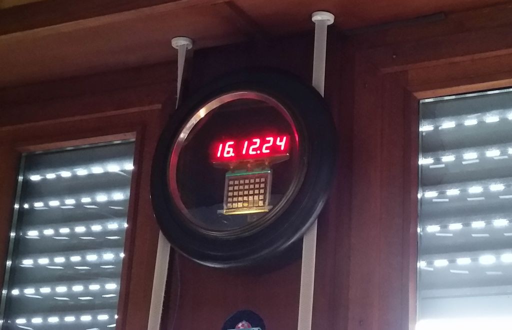
Here is the finalized product. Better than just standing in the shelf. And it feels good to know that the module is powered up and playing a role in the clock.
The Saturn-V LVDC clock is working. I ordered an acrylic window which will fit over the display. The one I have is too small. It will make the numbers look better. I´ll put the clock into a wooden case so it can be hung on the wall.
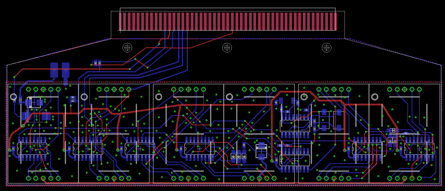
Here´s the PCB layout of the clock with the interface to the LVDC module: The parts are mounted behind the 1-inch 7-segment displays. The circuit is based on the schematic by danyk666, it´s a classical counter circuit which uses counters 4060 and 4026. It doesn´t need BCD to 7-segment decoders, as the ICs do the job already. A quick design here, not the most beautiful routing, but will do the job. Anyway, it´s a quick build.
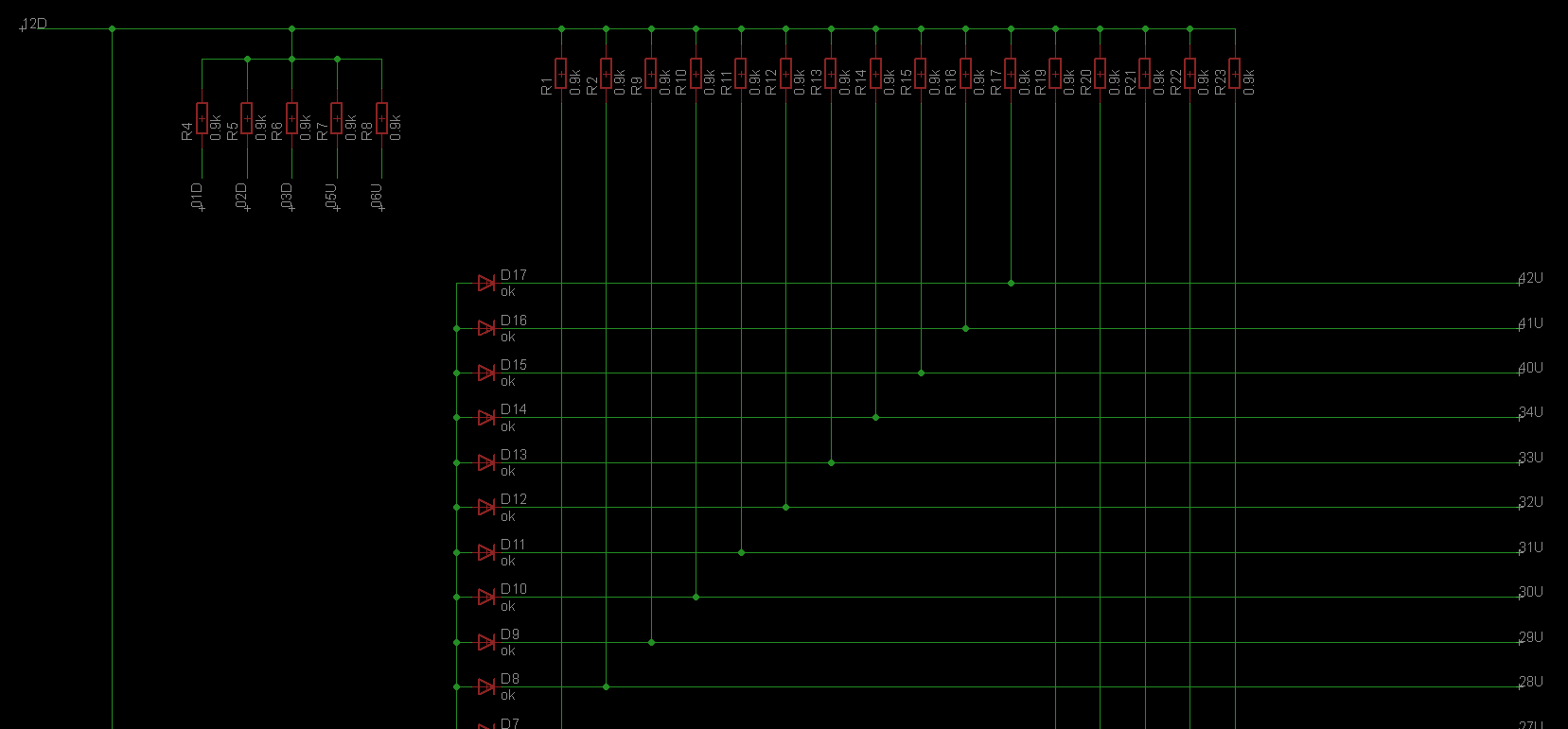
With a multimeter and and some time I was able to find the following structure:
It looks like a gigantic Diode-AND gate. The diodes have a common anode. I couldn´t find any isolated diodes or transistors.
What else could it be? Maybe a clock distribution circuit where the clock is decoupled by diodes? Or was it used for driving core memory? I don´t know.
However, I will stop the reverse engineering here, as it´s already enough in the circuit to be used in the clock. I will use the AND structure to flip the clock from 59 to 00.
 Paul Kocyla