Virgilius1995
-
Non mainline design alternative 2 +Note
01/30/2019 at 09:49 • 0 commentsnote: Why I upload so many logs about physical design. I've not been able to purchase any components yet so most of the work I can do is the theoretical... As soon as possible I'll start focusing on wiring and programming but till then I prefer to catalog everything encase I end up having to roll back some changes.
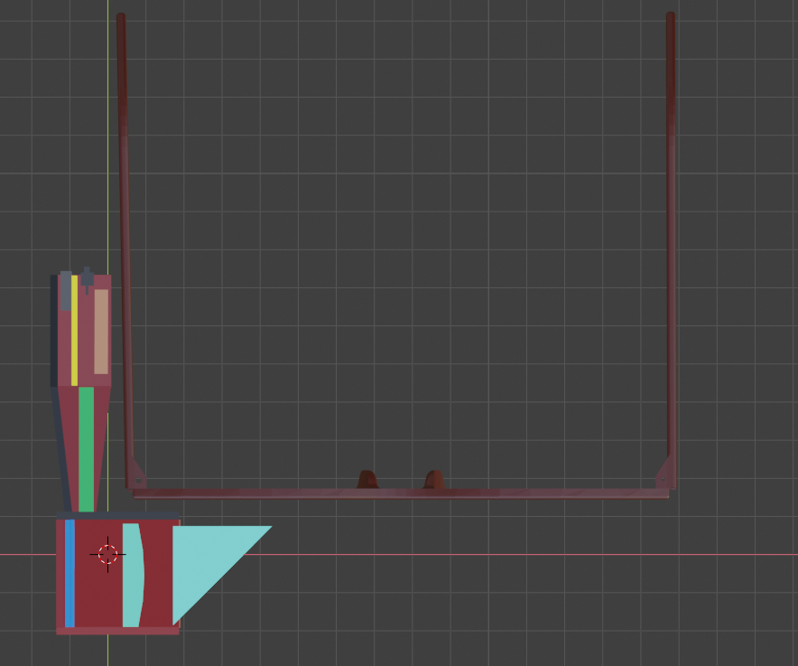
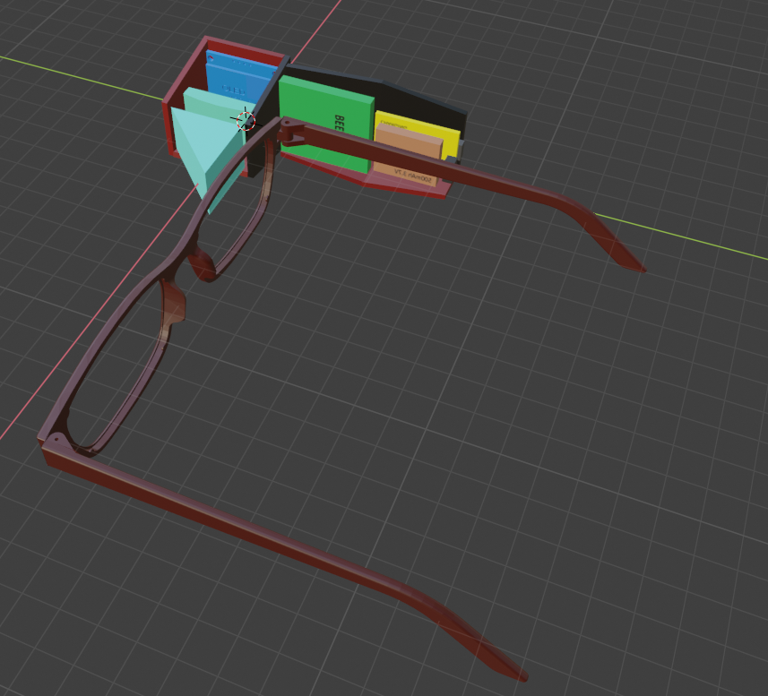
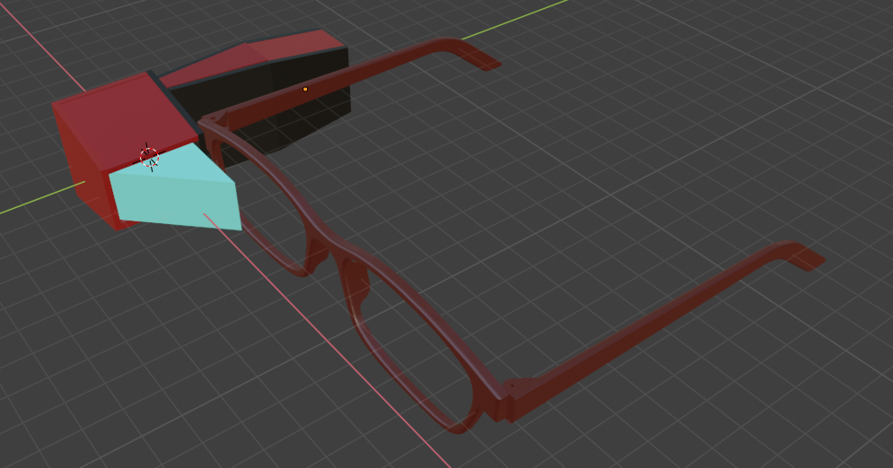
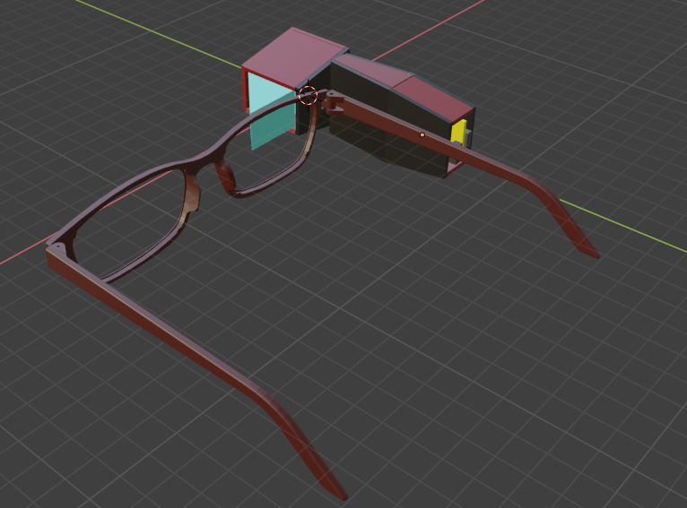
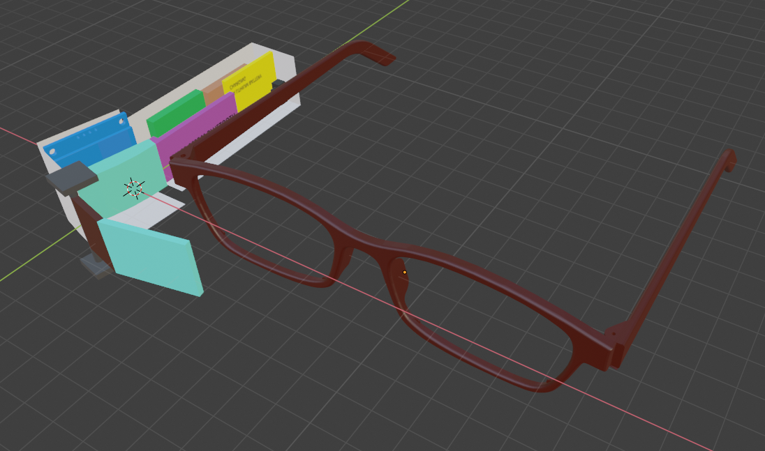
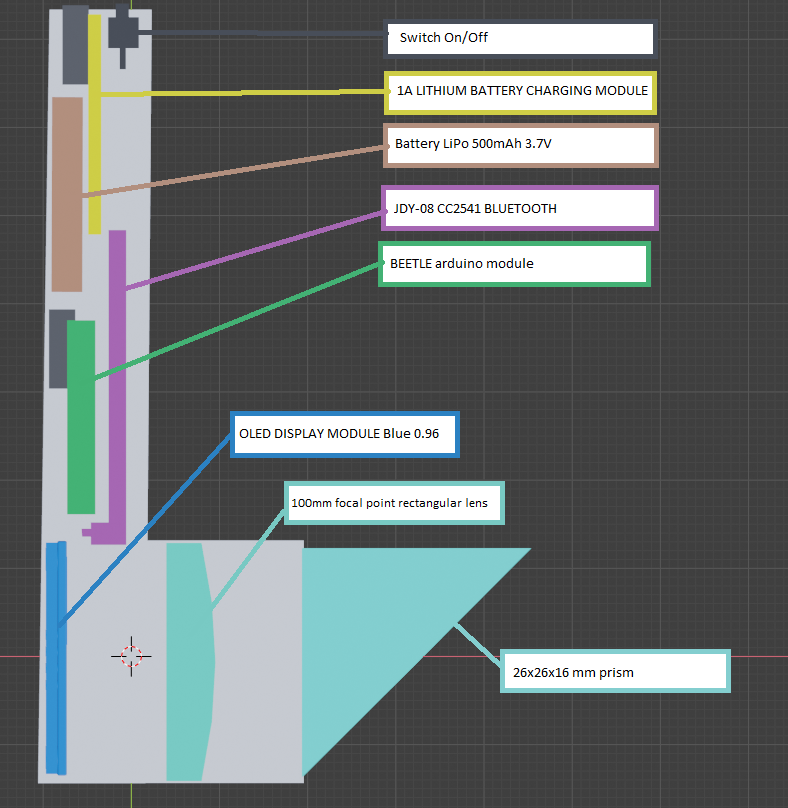
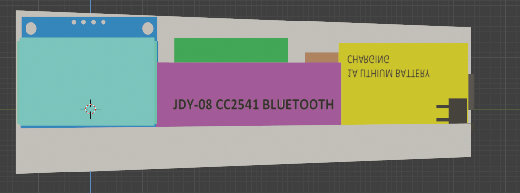
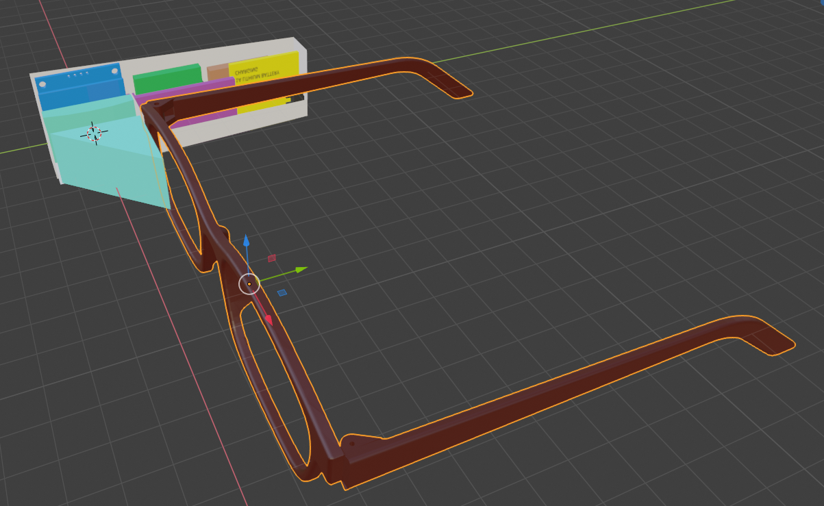
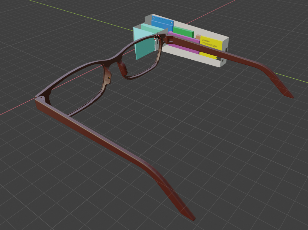
Of-shoot design 2: Using a Beetle with Bluetooth
Replacing the standard beetle board with one that has built in Bluetooth:
![]()
![]()
![]()
![]()
-
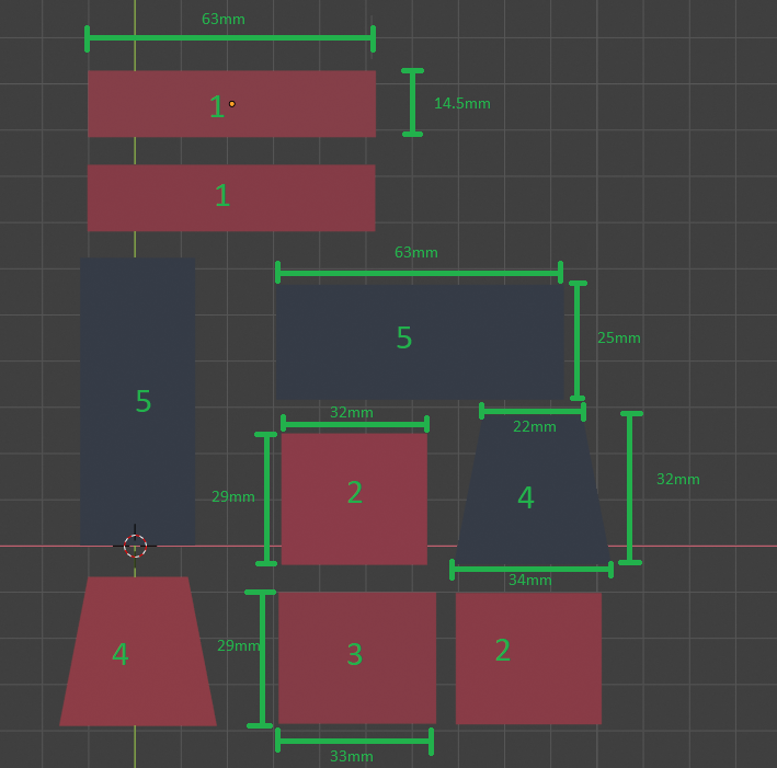
Initial Planning stage 6(Case design rev.1)
01/30/2019 at 08:03 • 0 commentsOuter casing initial design:
The initial idea is to have a body made from 2 mm thick spray painted cut Perspex. Depending on the weight and strength this might be replaced with a printed body if I find it necessary.
These renders are more or less to scale but a proper blue print will be done when I finish the final cuts and I’ve figured out how much space the wires will take.
As is ,the measurements are all less than a mm to big so the components can be sanded to a perfect fit
Objects with the same number are also the same shape.
Measurements:
![]()
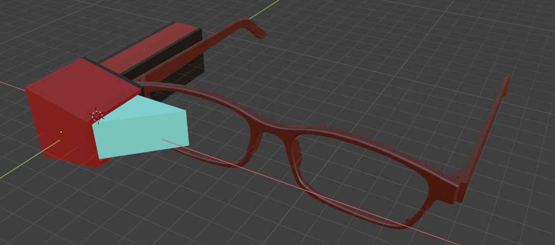
Proposed construction:
![]()
-
Non mainline design alternative 1
01/29/2019 at 19:37 • 0 commentsOf-shoot design: using Perspex instead of a prism
A possible alternative design using a Perspex sheet instead of a prism
![]()
![]()
![]()
-
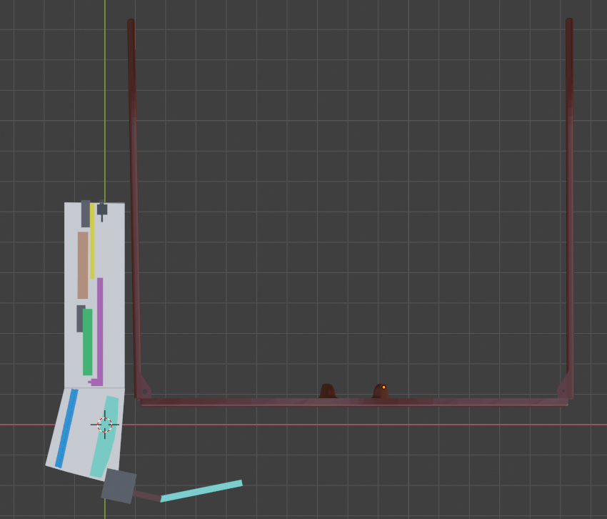
Initial Planning stage 5 Design iteration 2
01/29/2019 at 17:02 • 0 comments3D model renders Rev 2
Top down view
As with the previous design, this is still just a concept and is subject to change (Larger blocks are 1cmX1cm for scale)
![]()
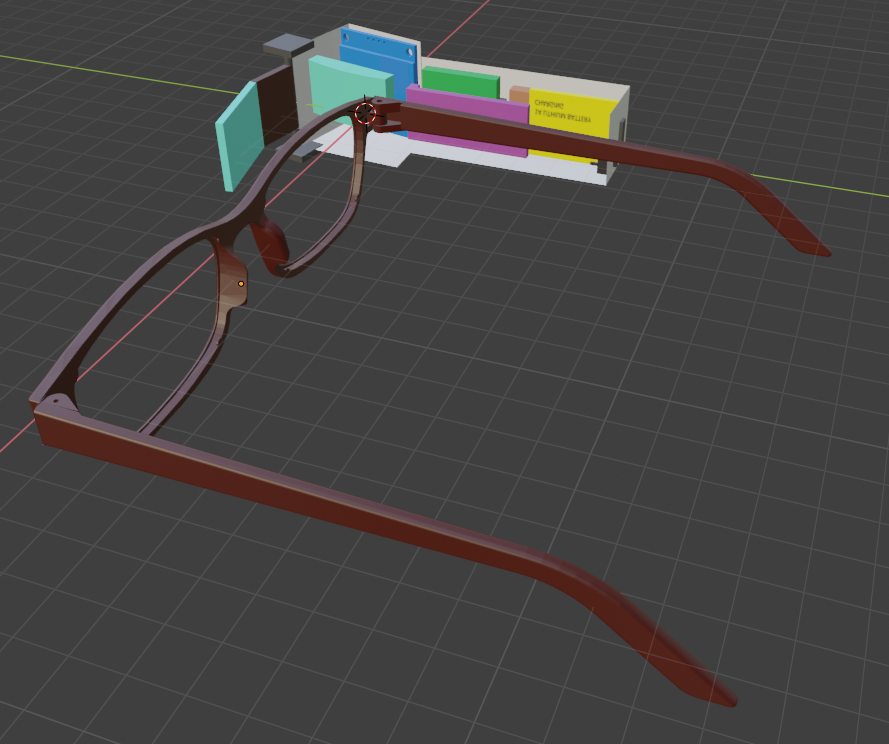
Other views:
![]()
![]()
![]()
-
Deprecated: Initial Planning stage 4 (First 3D renders)
01/29/2019 at 15:57 • 0 comments3D model renders Rev 1(Deprecated: Please see next iteration)
Top down view As with the previous design, this is still just a concept and is subject to change (Larger blocks are 1cm * 1cm for scale)

initial design Other views


-
Initial Planning stage 3
01/29/2019 at 13:19 • 0 commentsJust a simple sketch (partially to scale) to give an idea of the proposed layout.
Will try to upload a 3d model later today or tomorrow.
-
Initial Planning stage 2
01/29/2019 at 12:44 • 0 commentsRelevant software code found online unfiltered and unedited.
Since I am new to Arduino development I’ve gathered the following scripts from various online projects that have some code relevant to the project. I plan on using this code as a template for my own code to streamline the process since while I’m qualified in C++, I have no experience with Arduino. I’ve linked the original pages PLEASE SUPPORT THE ORIGINAL POSTERS
Receive Notification information (Arduino) (source: https://create.arduino.cc/projecthub/geny-studio/notification-iot-using-neopixel-and-smartphone-945e81?ref=user&ref_id=114809&offset=0)
#include <SoftwareSerial.h>
#include <Adafruit_NeoPixel.h>
#ifdef __AVR__
#include <avr/power.h>
#endif
#define PIN 10
#define NUMPIXELS 24
#define rxPin 4
#define txPin 3
SoftwareSerial BT(txPin, rxPin);
Adafruit_NeoPixel pixels = Adafruit_NeoPixel(NUMPIXELS, PIN, NEO_GRB + NEO_KHZ800);
int delayval = 50; // delay for half a second
void setup() {
BT.begin(9600);
Serial.begin(9600);
pixels.begin(); // This initializes the NeoPixel library.
}
void loop() {
if (BT.available() >0)
{
//Receive values from Notiduino Android App whenever it gets notification messages
//Use semicolon and comma as seperator to retrieve header message and RGB color value
String BT_receive_data = BT.readStringUntil((char)3);
String Message_Head = getValue(BT_receive_data, ';', 0);
String ColorValue = getValue(BT_receive_data, ';', 1);
int R = getValue(ColorValue, ',', 0).toInt();
int G = getValue(ColorValue, ',', 1).toInt();
int B = getValue(ColorValue, ',', 2).toInt();
Serial.println(Message_Head);
Serial.println(ColorValue);
for (int i = 0; i<NUMPIXELS; i++)
{
pixels.setPixelColor(i, pixels.Color(R, G, B)); // Moderately bright green color.
pixels.show(); // This sends the updated pixel color to the hardware.
delay(10);
pixels.setPixelColor(i, pixels.Color(0, 0, 0));
}
}
}
#pragma region get Value
String getValue(String data, char separator, int index)
{
int found = 0;
int strIndex[] = { 0, -1 };
int maxIndex = data.length() - 1;
for (int i = 0; i <= maxIndex && found <= index; i++){
if (data.charAt(i) == separator || i == maxIndex){
found++;
strIndex[0] = strIndex[1] + 1;
strIndex[1] = (i == maxIndex) ? i + 1 : i;
}
}
return found > index ? data.substring(strIndex[0], strIndex[1]) : "";
}
#pragma endregion
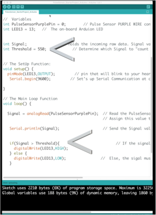
Receive Heartrate information(Arduino)(Source: https://pulsesensor.com/pages/code-and-guide)
Display heart rate (Arduino) (Source: http://www.xtronical.com/basics/heart-beat-sensor-ecg-display/)
#define OLED_Address 0x3C
Adafruit_SSD1306 oled(1);
int x=0;
int lastx=0;
int lasty=0;
int LastTime=0;
bool BPMTiming=false;
bool BeatComplete=false;
int BPM=0;
#define UpperThreshold 550
#define LowerThreshold 500
void setup() {
oled.begin(SSD1306_SWITCHCAPVCC, OLED_Address);
oled.clearDisplay();
oled.setTextSize(2);
}
void loop()
{
if(x>127)
{
oled.clearDisplay();
x=0;
lastx=x;
}
int value=analogRead(0);
oled.setTextColor(WHITE);
int y=60-(value/16);
oled.writeLine(lastx,lasty,x,y,WHITE);
lasty=y;
lastx=x;
// calc bpm
if(value>UpperThreshold)
{
if(BeatComplete)
{
BPM=millis()-LastTime;
BPM=int(60/(float(BPM)/1000));
BPMTiming=false;
BeatComplete=false;
}
if(BPMTiming==false)
{
LastTime=millis();
BPMTiming=true;
}
}
if((value<LowerThreshold)&(BPMTiming))
BeatComplete=true;
// display bpm
oled.writeFillRect(0,50,128,16,BLACK);
oled.setCursor(0,50);
oled.print(BPM);
oled.print(" BPM");
oled.display();
x++;
}
Display notifications (Arduino) and Display time (Arduino) (source: https://circuitdigest.com/microcontroller-projects/build-an-arduino-smart-watch-by-interfacing-oled-display-with-android-phone)
#include<SoftwareSerial.h>
SoftwareSerial Serial1(10, 11);
#include <SPI.h>
#include <Wire.h>
#include <Adafruit_GFX.h>
#include "Adafruit_SSD1306.h"
#define OLED_RESET 4
Adafruit_SSD1306 display(OLED_RESET);
#define NUMFLAKES 10
#define XPOS 0
#define YPOS 1
#define DELTAY 2
#define LOGO16_GLCD_HEIGHT 16
#define LOGO16_GLCD_WIDTH 16
String str = "";
byte h = 0;
byte m = 0;
byte S = 0;
String dmy, time, network, battery, inNumber, s;
byte centerX = 24;
byte centerY = 39;
byte Radius = 24;
double RAD = 3.141592 / 180;
double LR = 89.99;
void showTimeAnalog(int center_x, int center_y, double pl1, double pl2, double pl3)
{
double x1, x2, y1, y2;
x1 = center_x + (Radius * pl1) * cos((6 * pl3 + LR) * RAD);
y1 = center_y + (Radius * pl1) * sin((6 * pl3 + LR) * RAD);
x2 = center_x + (Radius * pl2) * cos((6 * pl3 - LR) * RAD);
y2 = center_y + (Radius * pl2) * sin((6 * pl3 - LR) * RAD);
display.drawLine((int)x1, (int)y1, (int)x2, (int)y2, WHITE);
}
void digitalClock()
{
display.setTextSize(1);
display.setTextColor(WHITE);
display.setCursor(60, 20);
display.println(dmy);
display.setTextSize(2);
display.setCursor(60, 30);
display.println(time);
display.display();
delay(2000);
}
External Software used(TBD):
- Notiduino APK
-
Initial Planning stage 1
01/29/2019 at 11:49 • 0 commentsInitial proposal information:
Smart glasses planning stage 1
Software Components(Necessary)
- Identify notifications and time (android)
- Transfer information (android)
- Receive Notification information (Arduino)
- Receive Heartrate information(Arduino)
- Display heart rate (Arduino)
- Display time (Arduino)
- Display notifications (Arduino)
Software components (Possibly)
- Menu system
Hardware components
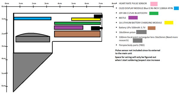
- HEART RATE PULSE SENSOR
- OLED DISPLAY MODULE Blue 0.96 INCH 128X64 4PIN
- JDY-08 CC2541 BLUETOOTH
- BEETLE
- 1A LITHIUM BATTERY CHARGING MODULE
- Battery LiPo 500mAh 3.7V
- 30x30mm prism
- 100mm focal point rectangular lens 16x26mm (Need more research)
- Perspex body parts (TBD)
Smart glasses: Notifications and heart-rate
(Inspired by work from Alain Mauer)