-
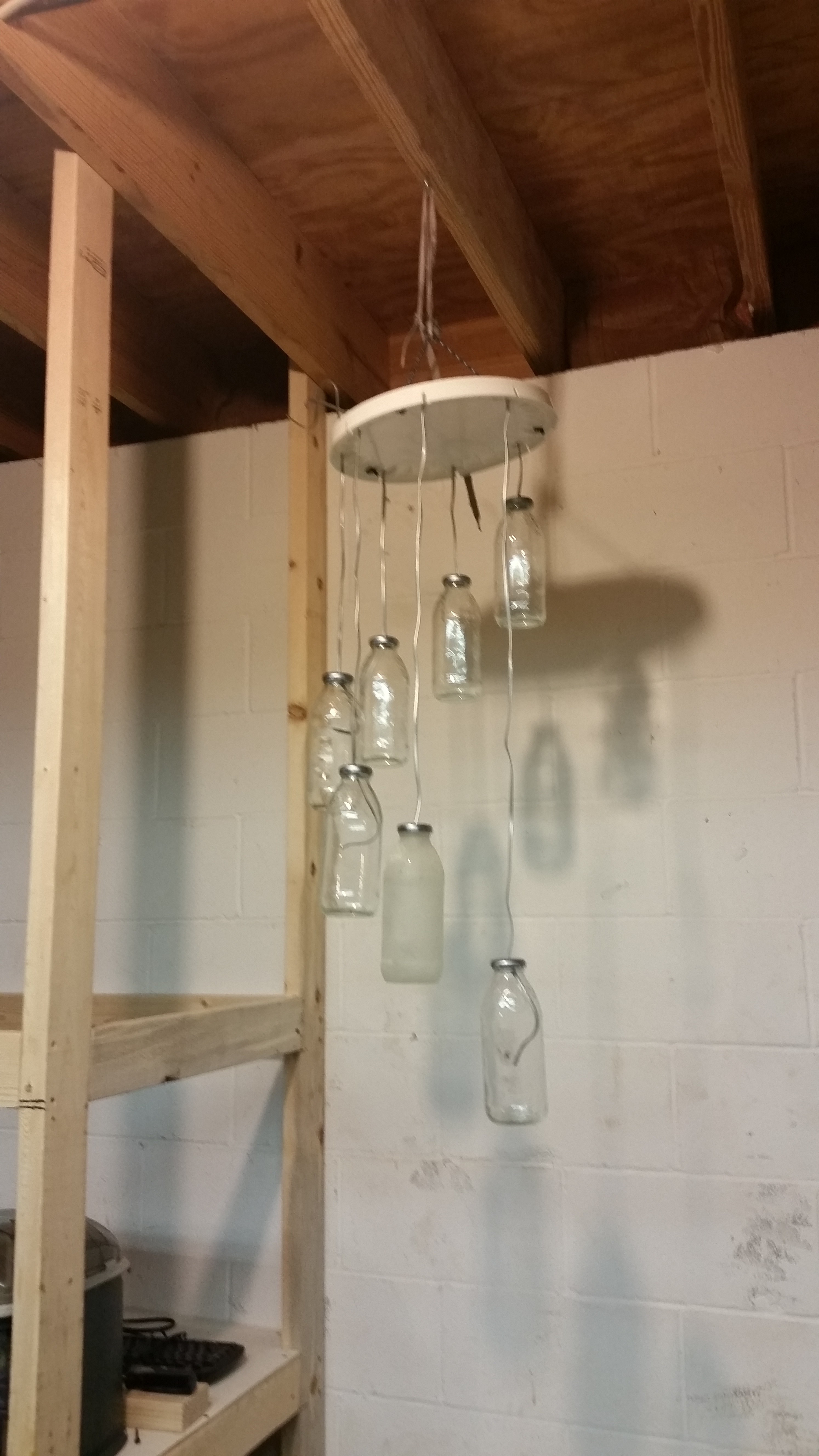
Just a pic for now
04/23/2016 at 17:20 • 0 commentsI'm gonna get back to working on this soon, but I wanted to upload a pic of it hanging up
![]()
Hopefully will have more done on this later this week, stay tuned for updates!
-
Hanging and Mockup
03/27/2015 at 02:22 • 0 commentsI finally decided to pick this project back up after a long hiatus. It was originally entered in the 2014 Hackaday Prize, but after I read the theme of this year's prize, I thought it would fit well.
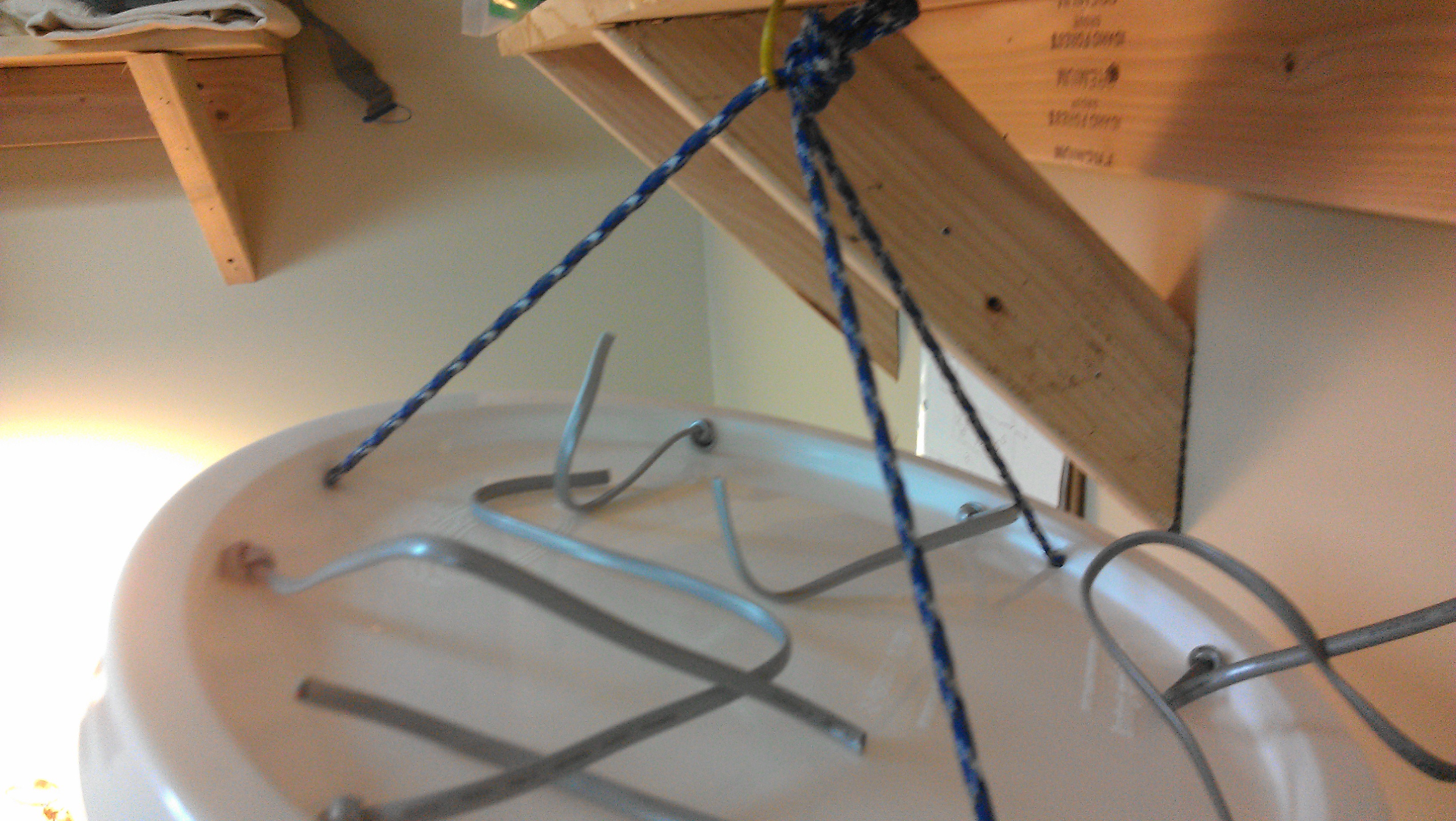
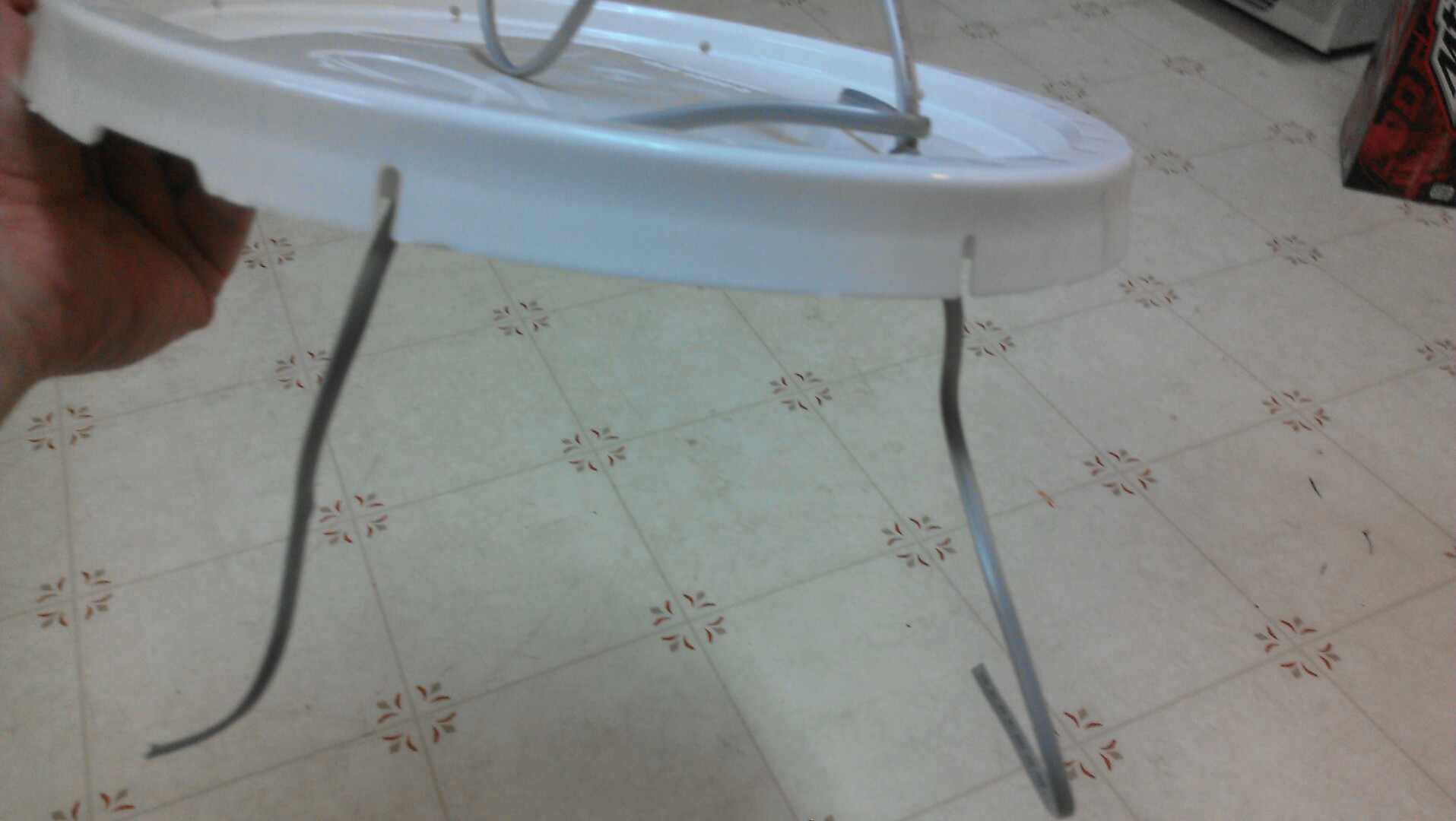
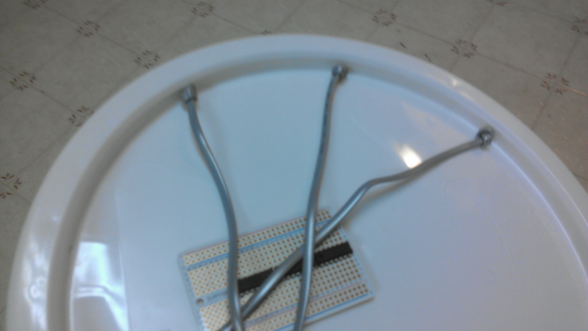
I left off at finding a mounting system and I have decided to use standard 550 paracord. It keeps with the trash theme, you should be able to find scraps in the lengths needed. Holes are drilled every 120 degrees around the circle and then tied together:
![]()
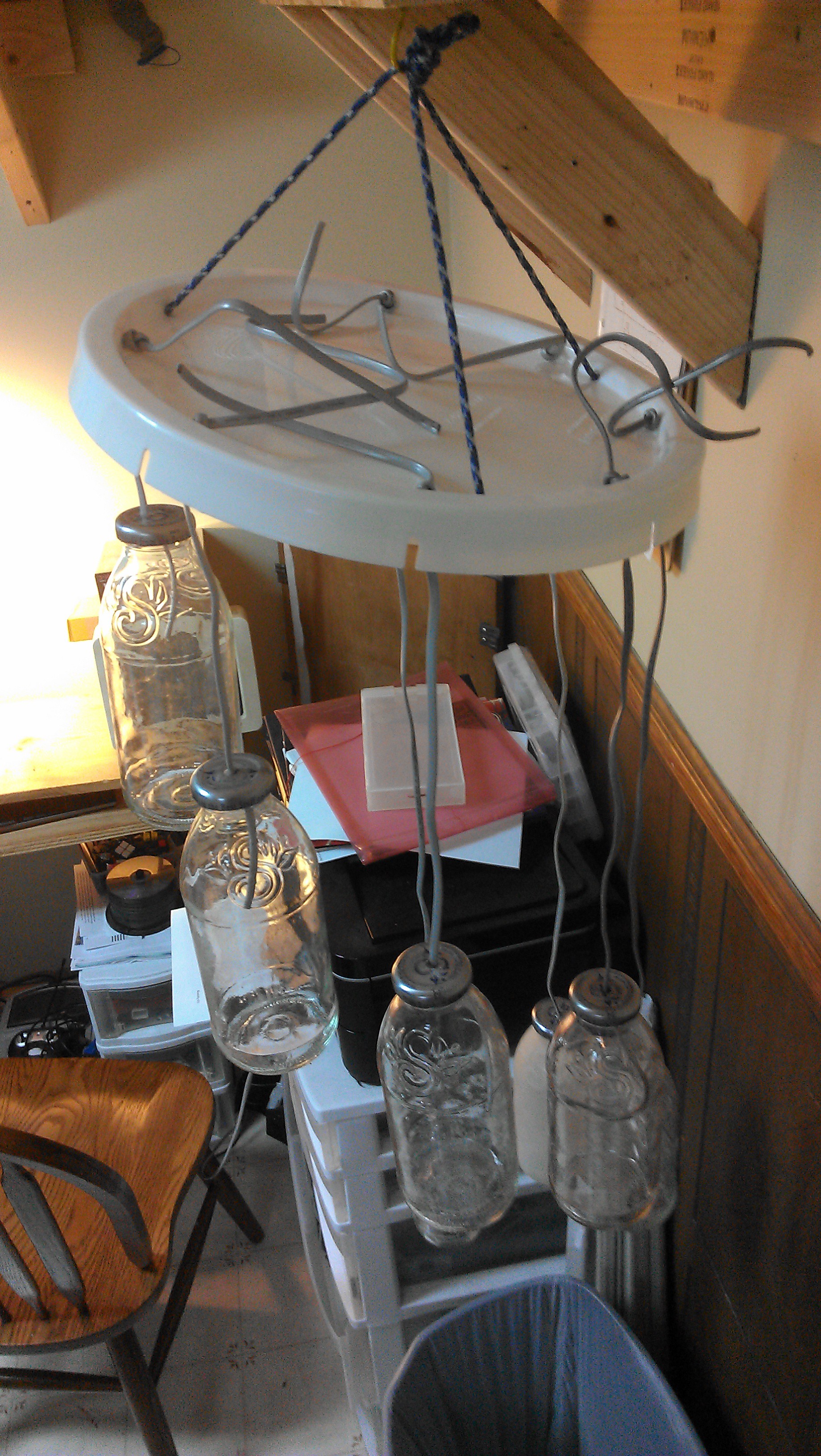
Protip for working on paracord: When burning the frayed ends, don't hold the flaming rope over your hand. It will drip molten nylon onto your fingers. Anyway, here's the mockup, although it's missing one of the bottle assemblies, so it's not balanced:
![]()
Hardware is almost completed, I just have to hit the bottles with the glass frosting paint. After that, it's just code and then I'm in business!
-
Mounting/drilling
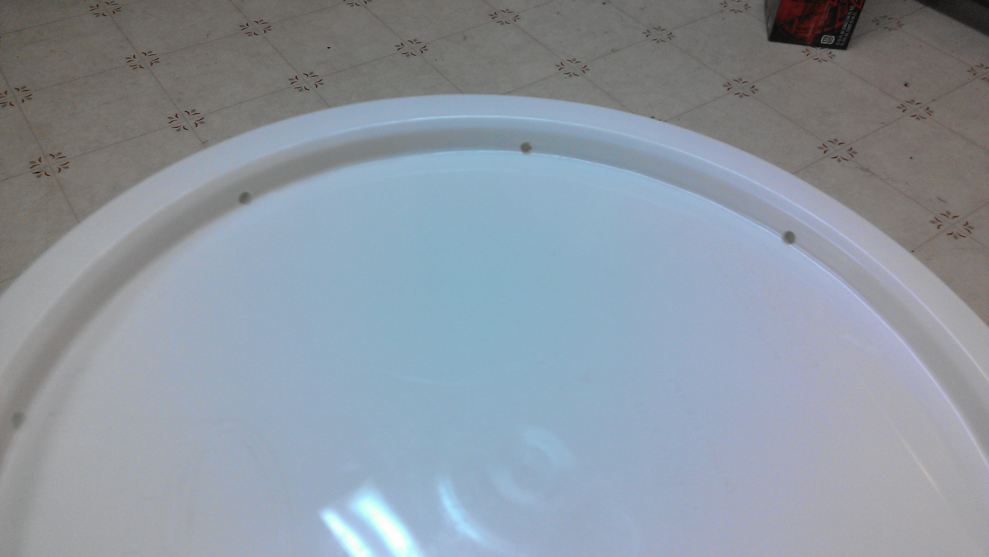
08/17/2014 at 06:24 • 0 commentsJust a quick update, been super busy registering for my last semester at school. I have drilled the holes in the lid I am using as the base of the project.
![]()
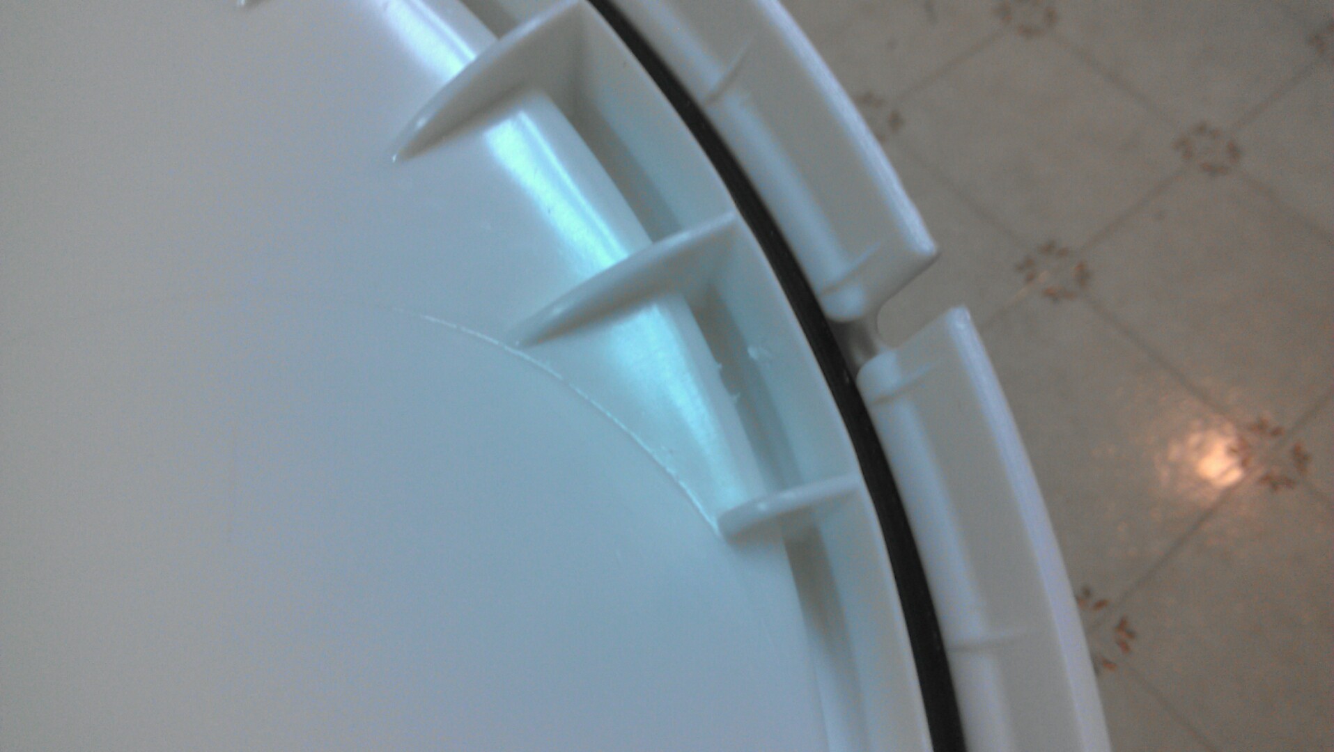
It was easy to space them out, since there were eight equally spaced notches in the side of the lid to line everything up with.
![]()
I think this is the best place for the holes structurally, with the support of those ridges on the inside. Also I removed that rubber ring, it is not needed for my application.
![]()
I chopped one phone cord up and started pulling it through the holes while knotting one end to prevent slip through. Here is all I completed before decided to pass out tonight:
![]()
I'm going to try to get the skeleton constructed before the deadline to the contest. I know it isn't necessary, but I think it will look better.
-
Moving
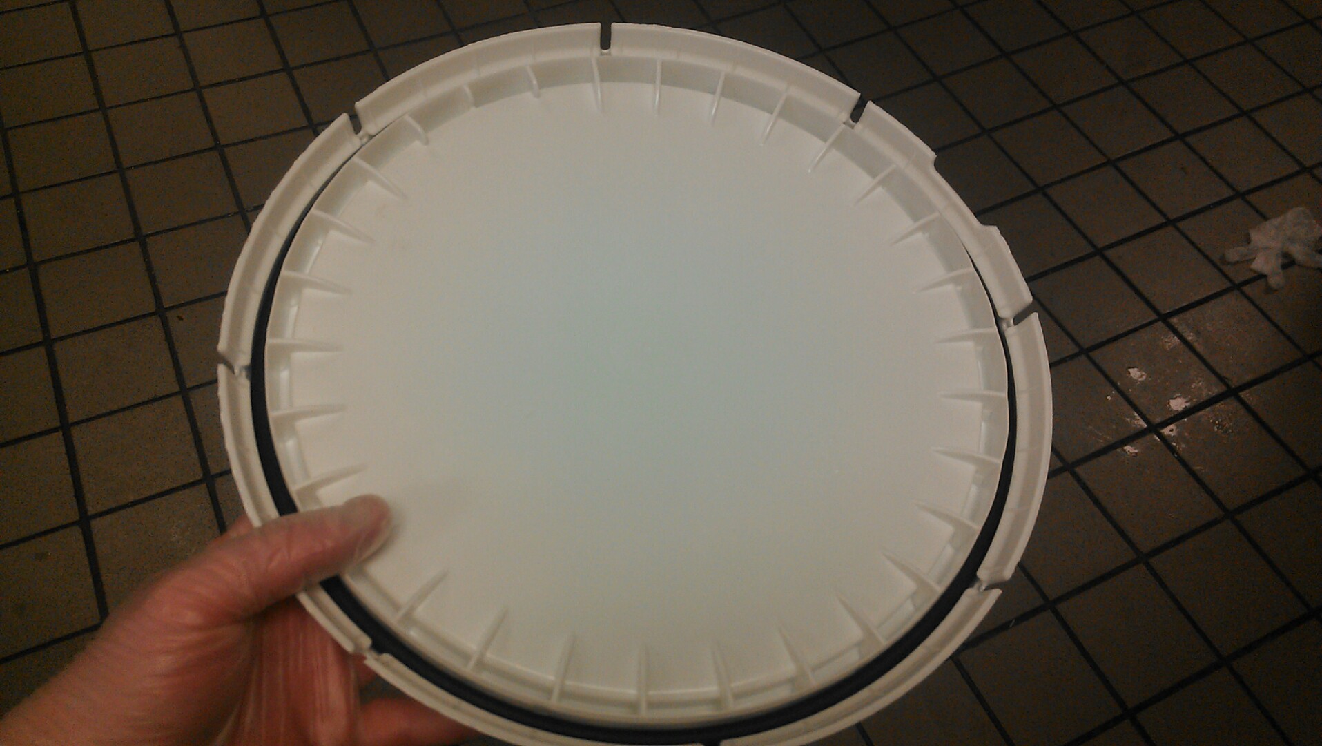
08/09/2014 at 17:25 • 0 commentsI have been moving across town the past couple weeks for cheaper rent and I haven't had much time to work on my projects. Also, half the stuff is in boxes right now and my workbench(I use the term loosely) is empty and waiting to be rebuilt. However, I have decided what I'm gonna use as the base:
![]()
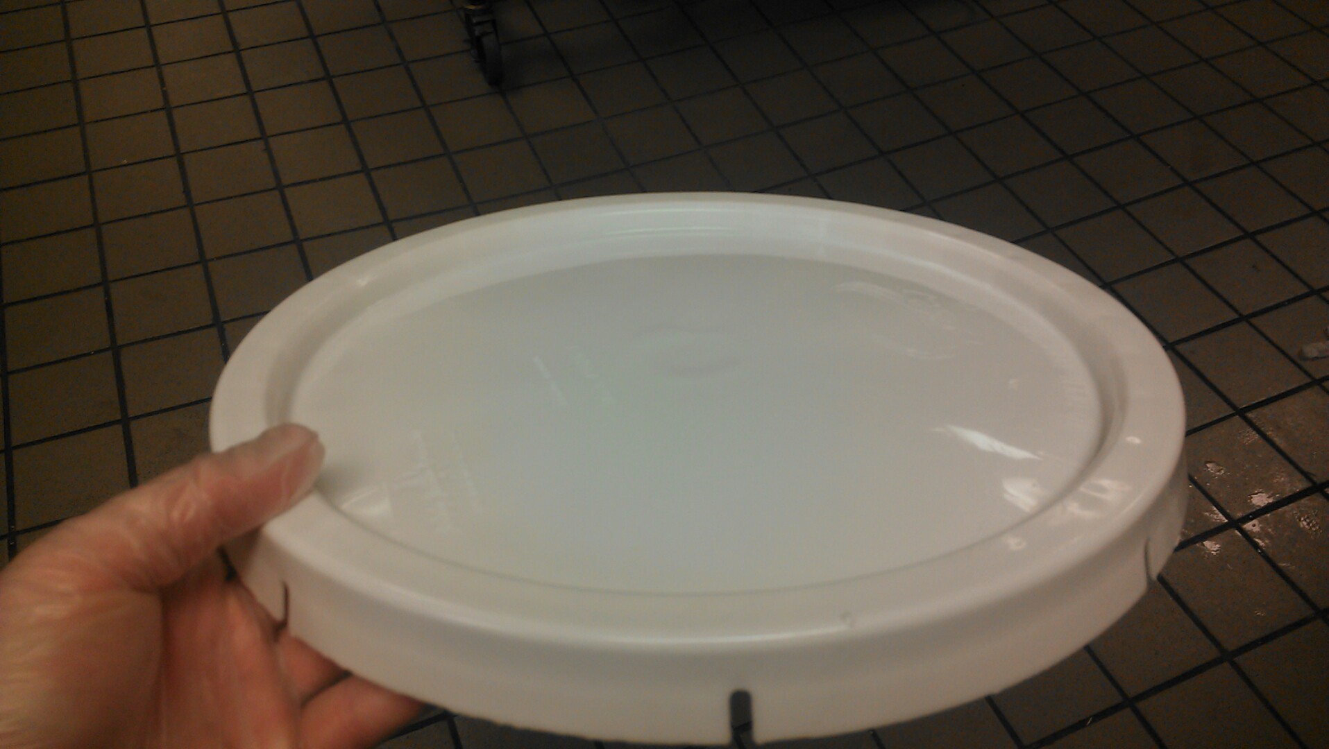
A lid to a five gallon pickle bucket sourced for free from a local business. They were just going to throw it out anyway, so this goes well with my trash theme.
![]()
It also has eight evenly spaced notches cut in the lid, which is the same number of lights I will be using. Although I could just measure the angles, this will save time and effort as I can just line up my holes and go. The last part of my project came in the mail a couple days ago:
![]()
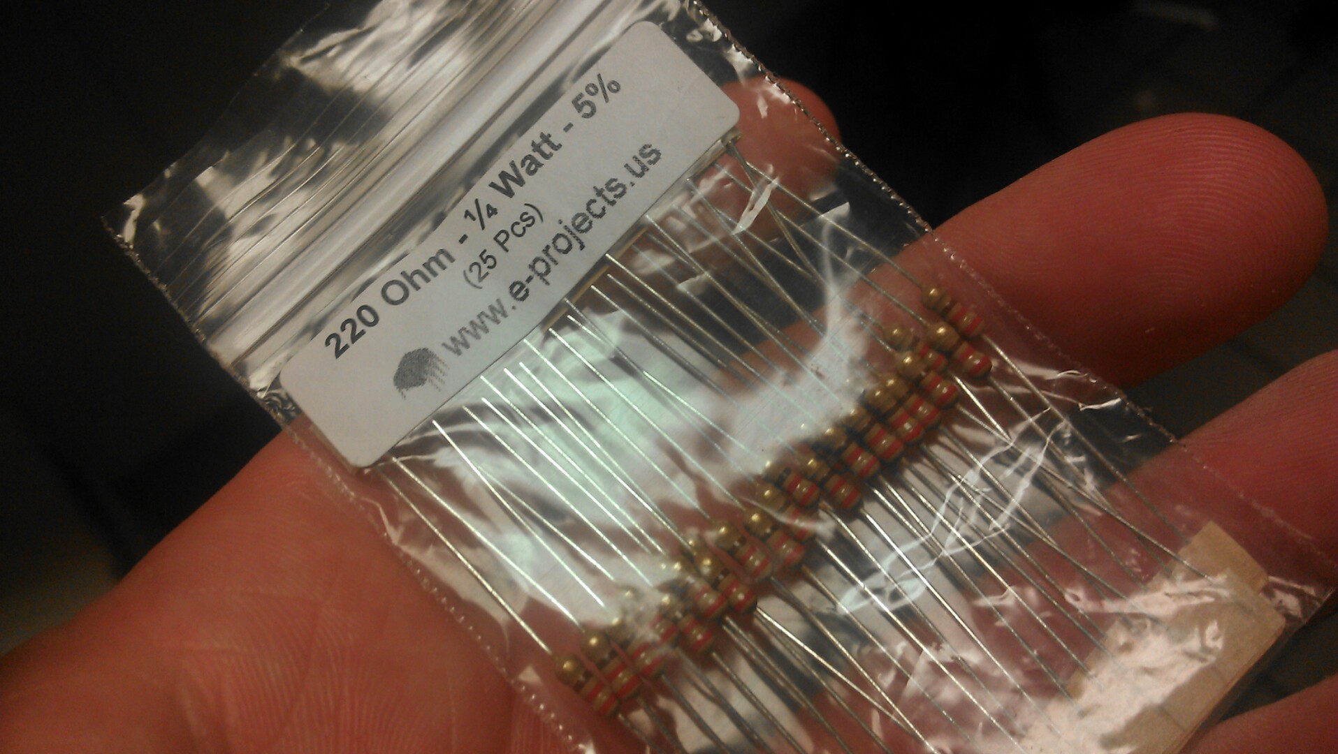
All the resistors I need for the LEDs!!! I have to put one on each LED. I was thinking about just putting one in each three bulb fixture on the ground side, but I may wish to turn on multiple LEDs in one fixture. Plus it is better practice to put the resistors on the hot side of the component. The next update should be me actually constructing the whole thing. I still need to figure out how to hang it, but not too bad so far.
-
Designing
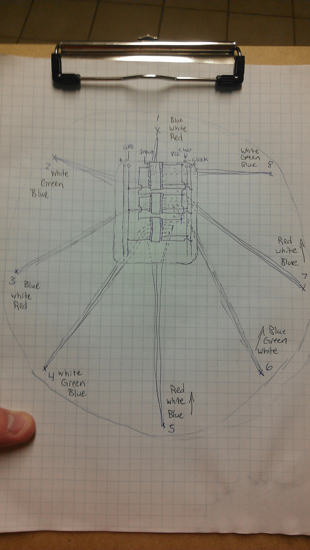
07/30/2014 at 08:56 • 0 commentsI have had the designs in my head for this for a while, but aside from basic sketches, I haven't drawn it all out. Also while doing this on graph paper with a pen, I realized I need to get some CAD skills for schematics.
![]()
The board in the middle houses the shift registers and all the output to the LEDs. The circle is the board (like wood) that it is mounted to from which the lights will hang. I also discovered that I will have to figure something out for the shift registers. If you're not familiar with how a shift register works, please visit Wikipedia as they have an excellent illustrated example. In the demo binary counter, I was only using one shift register; interfacing it with the arduino with three wires to tell it what to output on its eight pins. The code was something like:
int i
shiftout i
i = i + 1 as long as i =< 255
delay 1000
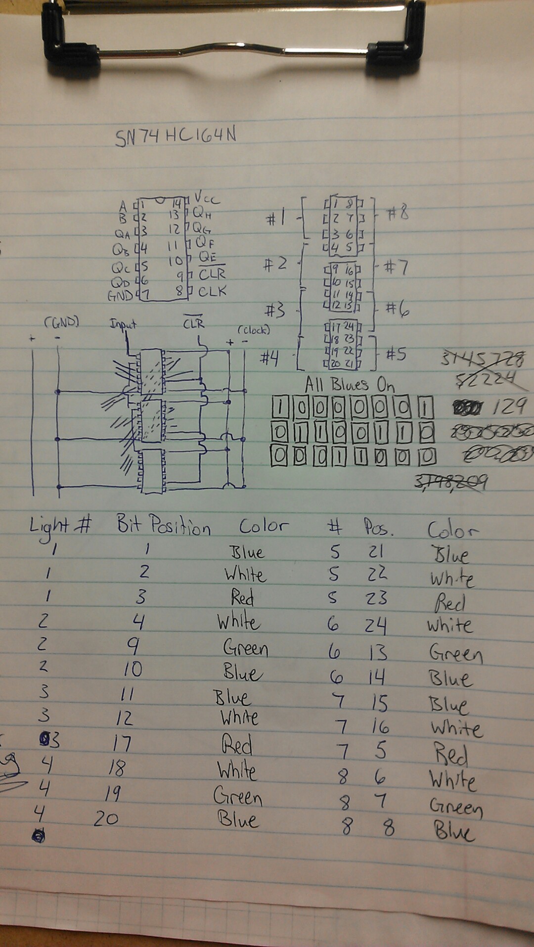
This code generates a 8 bit binary value that is output to the shift register. So for 1, it is 00000001. 2 would be 00000010, and so on. These values are interpreted by the shift register as which of its outputs to turn on or off. The problem lies in my use of multiple shift registers in which lights that are physically sequential are not always addressed sequentially with the binary value that is passed to the shift registers. I worked it out (again on paper):
![]()
In the top right is a diagram of the three shift registers if you only care about the outputs and their number and location. The brackets show which light every three outputs runs to. I made a table of every LED color, light fixture number it is in, as well as the bit number required to turn it on. I worked out what the three 8 bit packets would be if I wished to turn on one blue LED in every fixture, that is blocked out in the middle of the page. I mistakenly thought to calculate the 24 bit number in decimal before I realized that I would be sending three separate 8 bit packets instead of one that it wouldn't be possible for an 8 bit micro to handle.
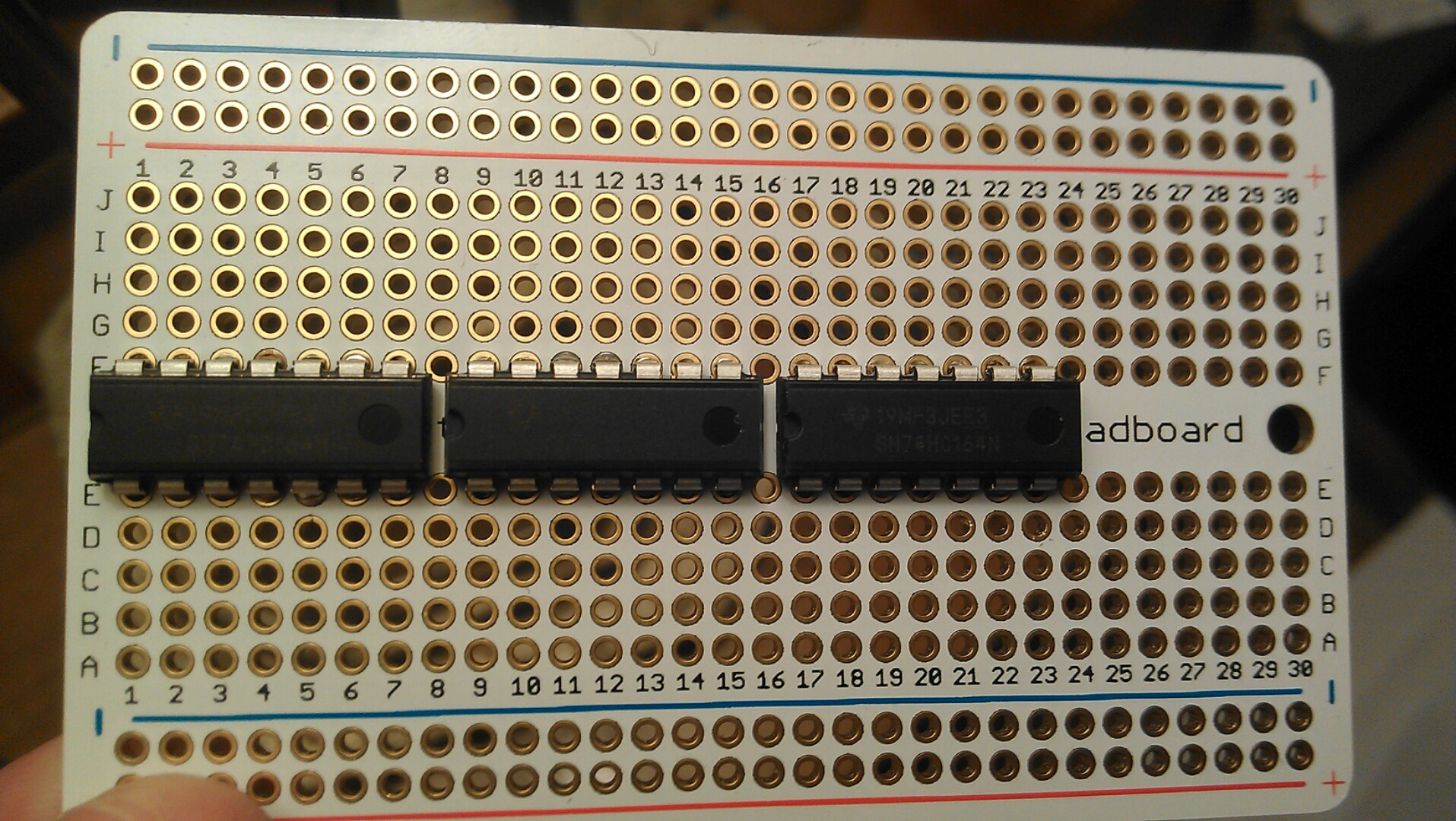
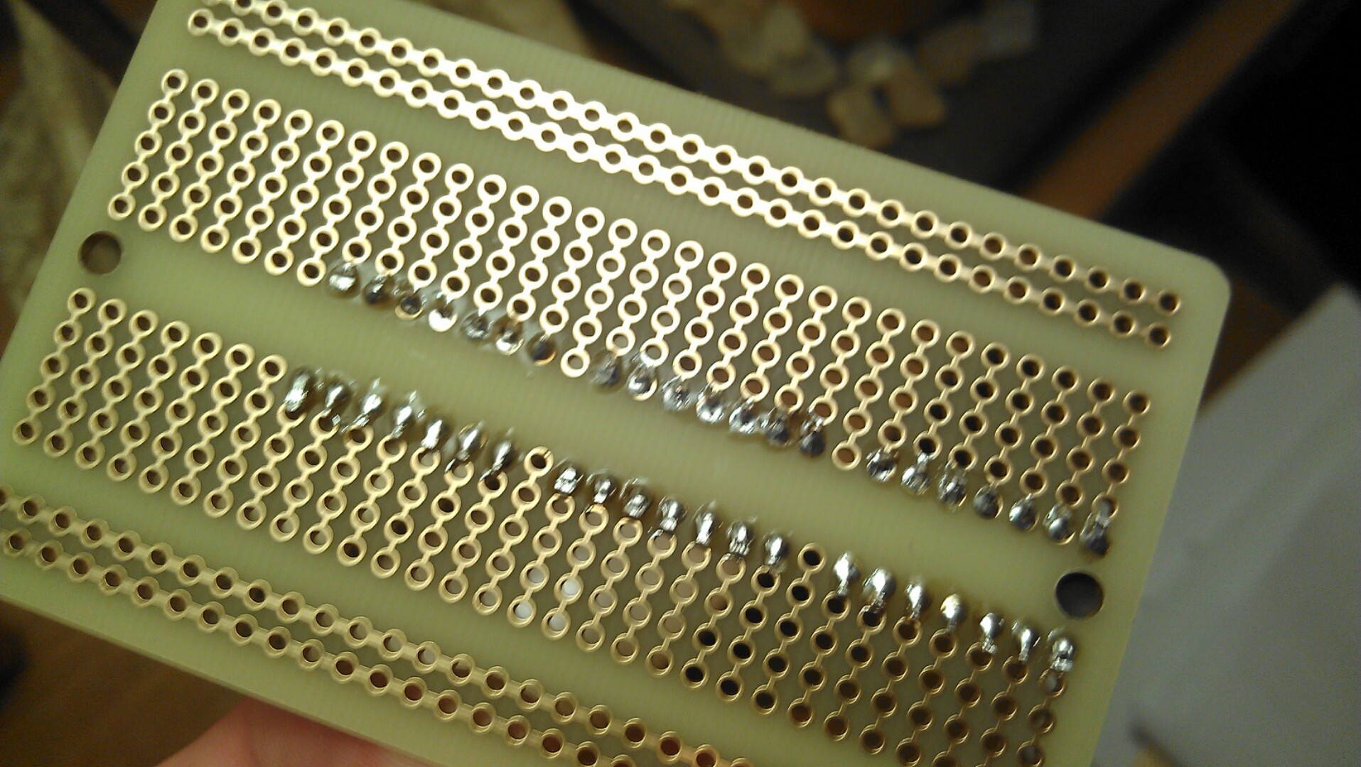
Sorry for droning on there, but I'm not even sure I adequately explained it. I also did some soldering today, although it is just the first part of much more to be done.
![]()
If you can read the schematics above, you'll see I plan to use the 4 total rails for positive, ground, clock, and clear lines to run to the shift registers. The input of the first will come from the arduino, and its output will feed into the input of the second. This is called cascading, as the bits that run over in the first shift register trickle down the second, and same for the third. I will also have to run a latch wire somewhere, but that is trivial. I hope the ICs work, I soldered as quickly as I could. I know I should have used a socket, but it just looks so pro without, lol
![]()
The next thing for me is to find the mount I'm going to use, so I can start getting the project laid down to it's final form.
-
Frosting Glass
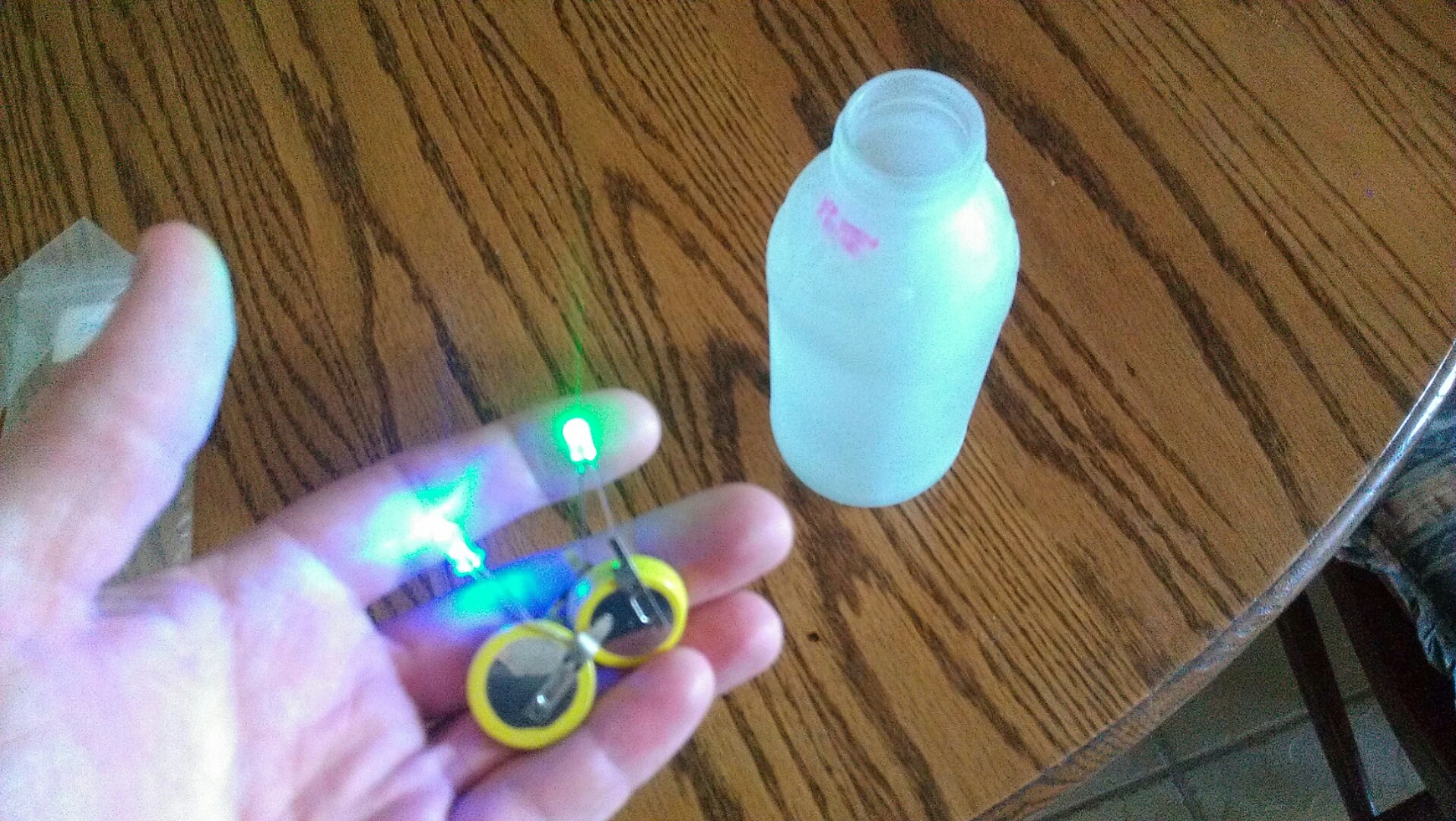
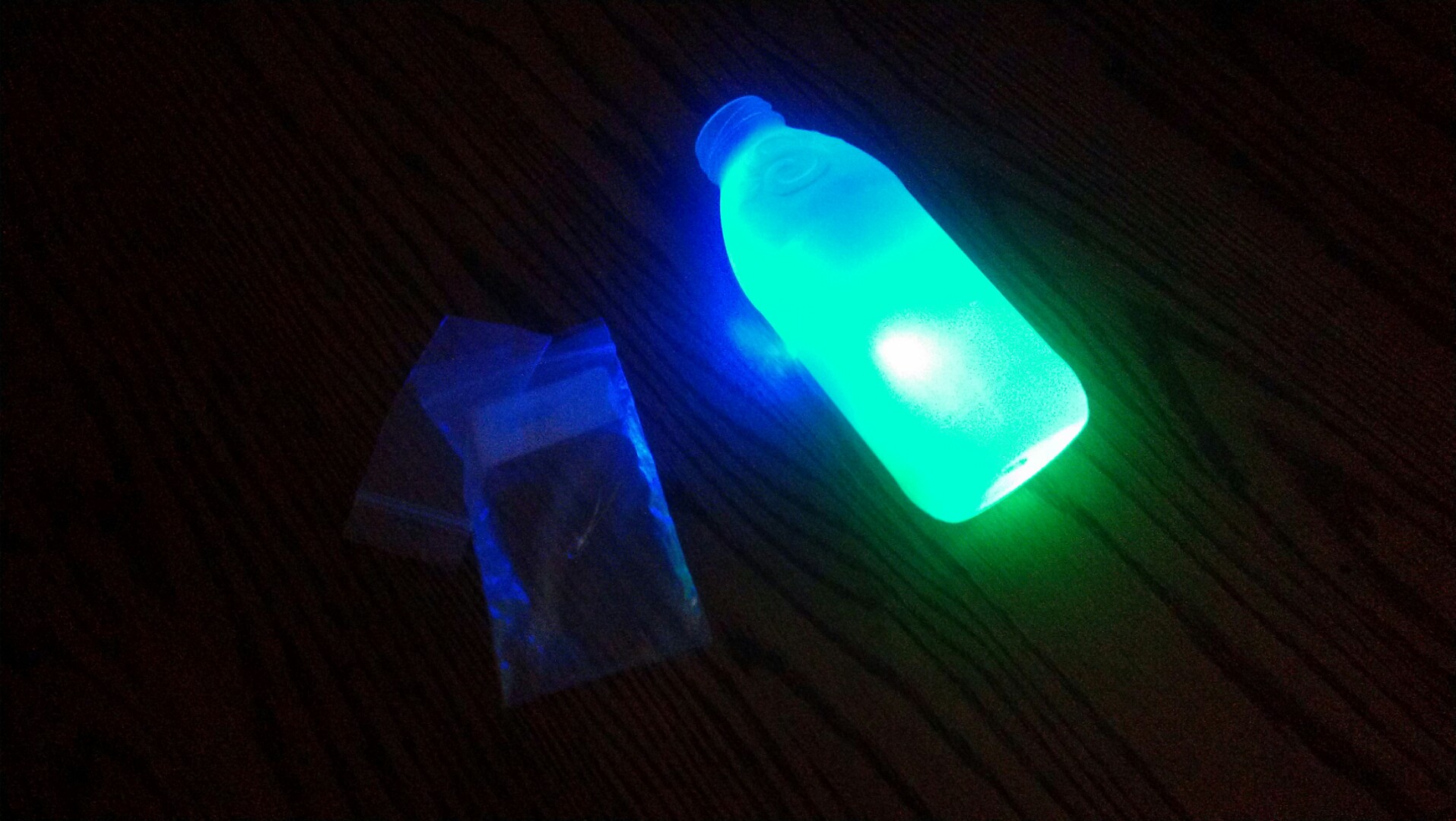
07/07/2014 at 20:32 • 0 commentsI have painted one of the bottles to test if I need multiple coats for the LED diffusion.
![]()
Just a quick test to see how the LEDs look through the bottle. I need to take alcohol to the date printout before frosting the other ones. The frosting is a spray paint type of thing.
![]()
I think this is acceptable, because they will be suspended and pointing downwards in the finished version.
So we'll skip the multiple coats for now and focus on cleaning up the bottles for painting. I've also heard of taking sandpaper to the LEDs to diffuse them more, something I will try when I can find my sandpaper.
-
The Hackaday Prize
06/29/2014 at 13:53 • 0 commentsCheck out my "2 minute introduction" video for my latest progress. I have one shift register rigged up just for testing purposes, and it is running a binary counter. The code is almost identical to the ShiftOut tutorial posted on Arduino.cc, so I feel like it would be plagarism to post it. Once I start work on the actual project, I will keep the github updated with the latest operationg code. Also I decided to enter this into the Hackaday Prize. I don't think it's changing the future of open hardware/software, but it will be well documented and it is something you can use to connect to people who have no idea what bits and bytes and code are all about
-
Testing... Testing...
06/28/2014 at 03:02 • 0 commentsI'm working on wiring up just one of the shift registers to the Nano I have and running a binary counter just as proof of concept. I haven't used shift registers before, nor have I messed with the Arduino Nano, although I know my way around with the regular 'duinos
Trash light
Using throwaway materials and electronics, create a custom mood light that emphasizes recycling/upcycling
 j0z0r pwn4tr0n