-
9. Completion
03/06/2019 at 18:11 • 0 commentsFinally all Lamps are modified according to the specifications ;-)
Lets see if there are further changes needed ;)
Thank you for bearing with me.
-
8. Integration
03/05/2019 at 18:56 • 0 commentsFinally i got some time to rework the Table Lamps. Since i got a not so specific PCB it was only a small effort.
- Remove the unknown IC
- Solder 4 wires to the lamps PCB (U_Batt, GND, Switch Signal, Lamp Signal)
- Add labels to the wires
- Solder the wires to the Barebone PCB
- Put everything together. It is really ********* that the Cables for the LED are that short...
- After this the last thing is to screw the lamp back together and add a label, that it will stay on forever ;)
- Be happy forever :)
- Only one Lamp left to rework which served as prototype.
-
7. PCB Assembly
02/22/2019 at 17:20 • 0 commentsRegarding the Assembly… It was really fast forward – only like 0,5h per PCB. An Advantage was that there are only 6 SMD components and one Jumperrow.
I also already tested the PCB and it worked! I didn’t really expect it but I appreciate it. Next Step is integration into the Lamp.
-
6. Fast Turnaround
02/22/2019 at 17:17 • 0 comments
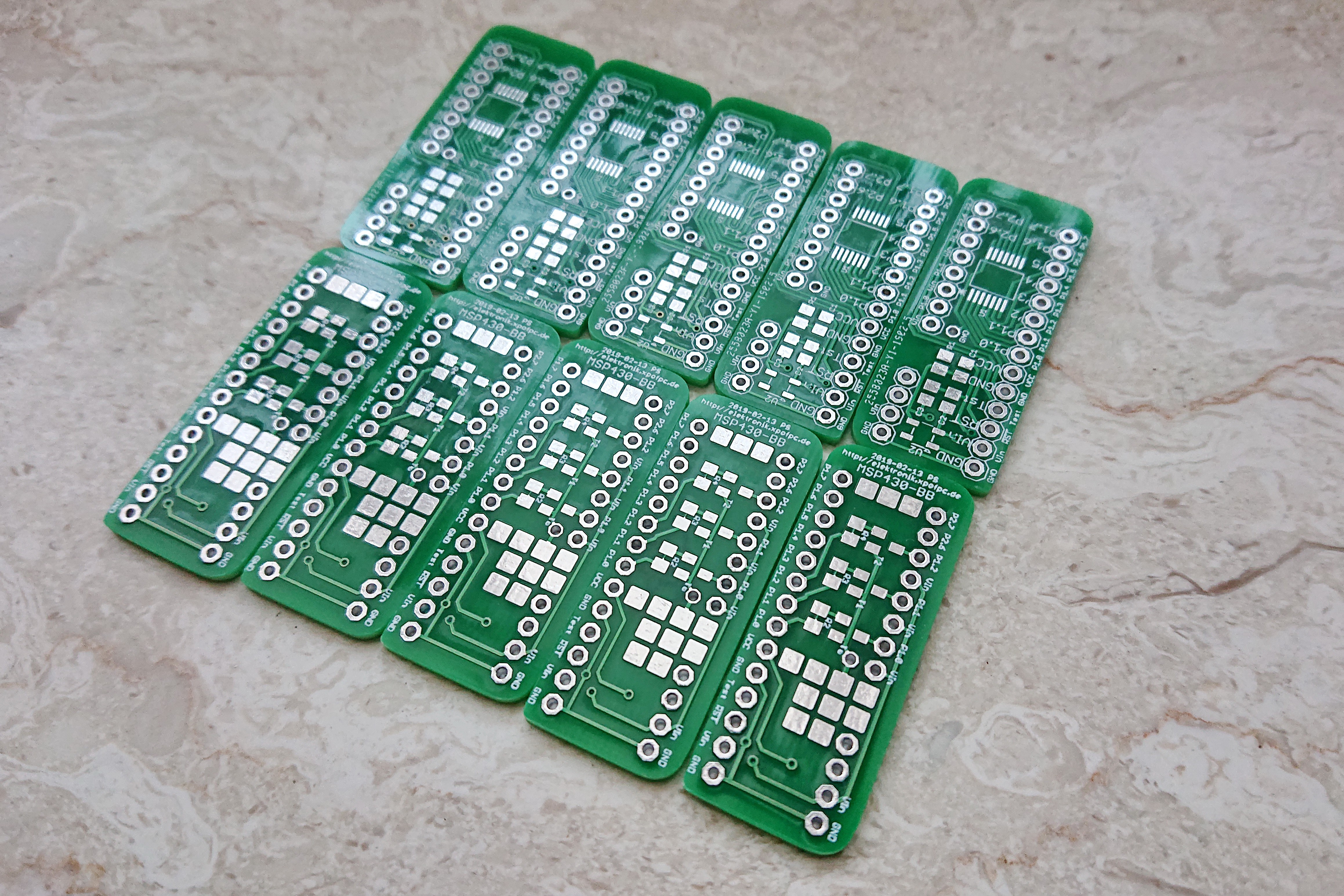
I ordered the PCBs via JLC PCB on 2019-02-15. They might have been delivered yesterday - but unfortunately, I wasn't at home...
Next Time I have to pay attention to not order more than 22€ ... so that in Germany there will be no taxes. And also need to pay attention, that the DHL Express doesn't take care of customs. Please note this if you consider to order 😉
Regarding the prices:
10 pcs = €1.78
+ Shipping Charge: €16.14
+ Customs €22,51
I also ordered some more Stuff at the LCSC.COM and an other PCB. If you balance your Order a bit better, I think it is a great resource for custom pcbs.
At the purple Company 9 pcs = $14,40 with free shipping. Considering the “Shipping Charge” and Taxes It is not a big gap.
Just as promised i finally received the PCBs.
-
5. The not so specialised µC Board
02/20/2019 at 20:15 • 0 comments
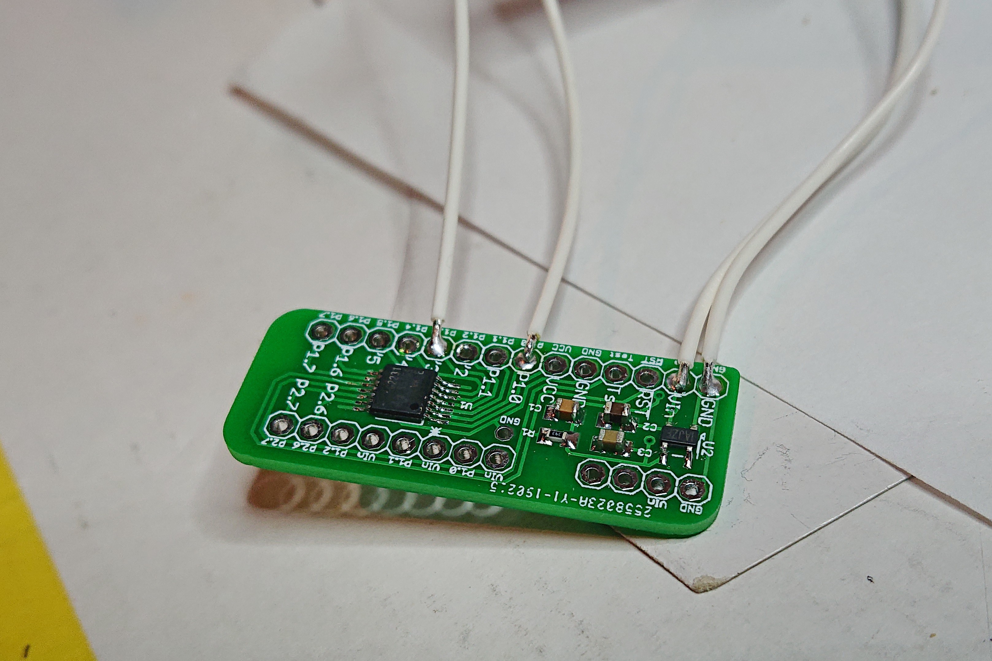
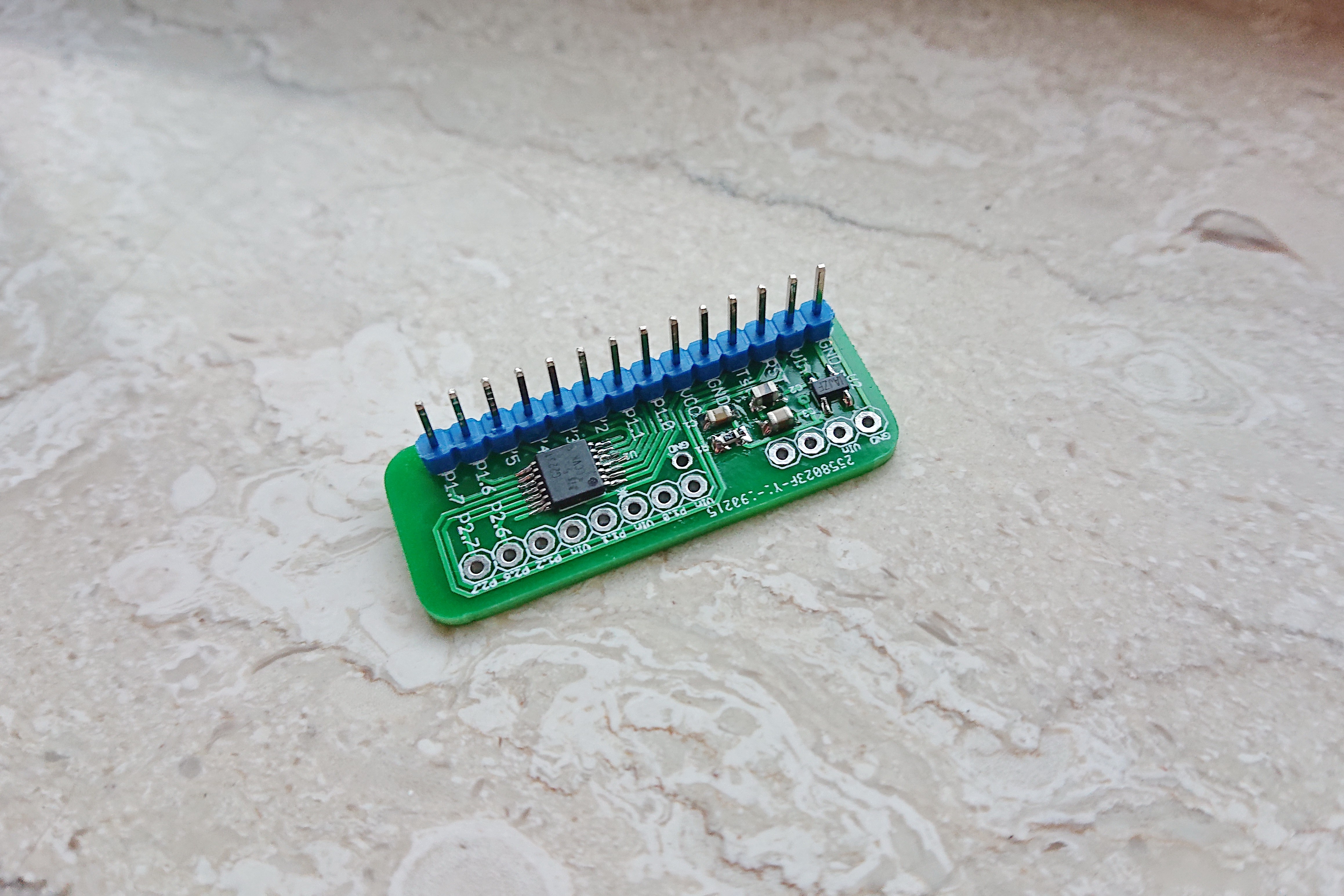
To realize the "Hack" for 5 lamps i just did a small PCB Design which should be sufficient to cover this project on a budget.
The Schematic is in General only a Breakout for the MSP430G2231EP. Therefore i call it the MSP430 Barebone PCB. I added a DC Converter for the µC and 3 Outputs which may feature a BC817 NPN Transistor:
There are also some emty Pads because of having is better than needing ;-)
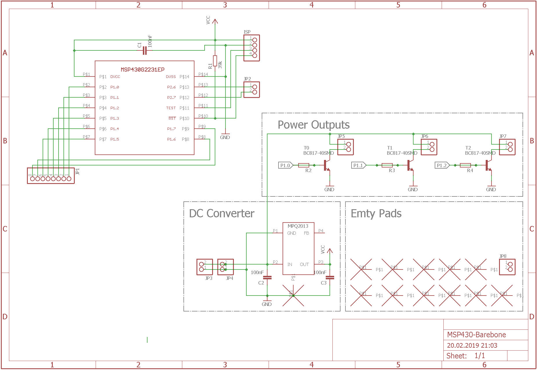
This is how the Desing looked like in Eagle :-)They also promised, that it will arrive this week ^^ (It is already shipping) Stay tuned.
-
4. MSP430 Tryout
02/14/2019 at 20:30 • 0 comments
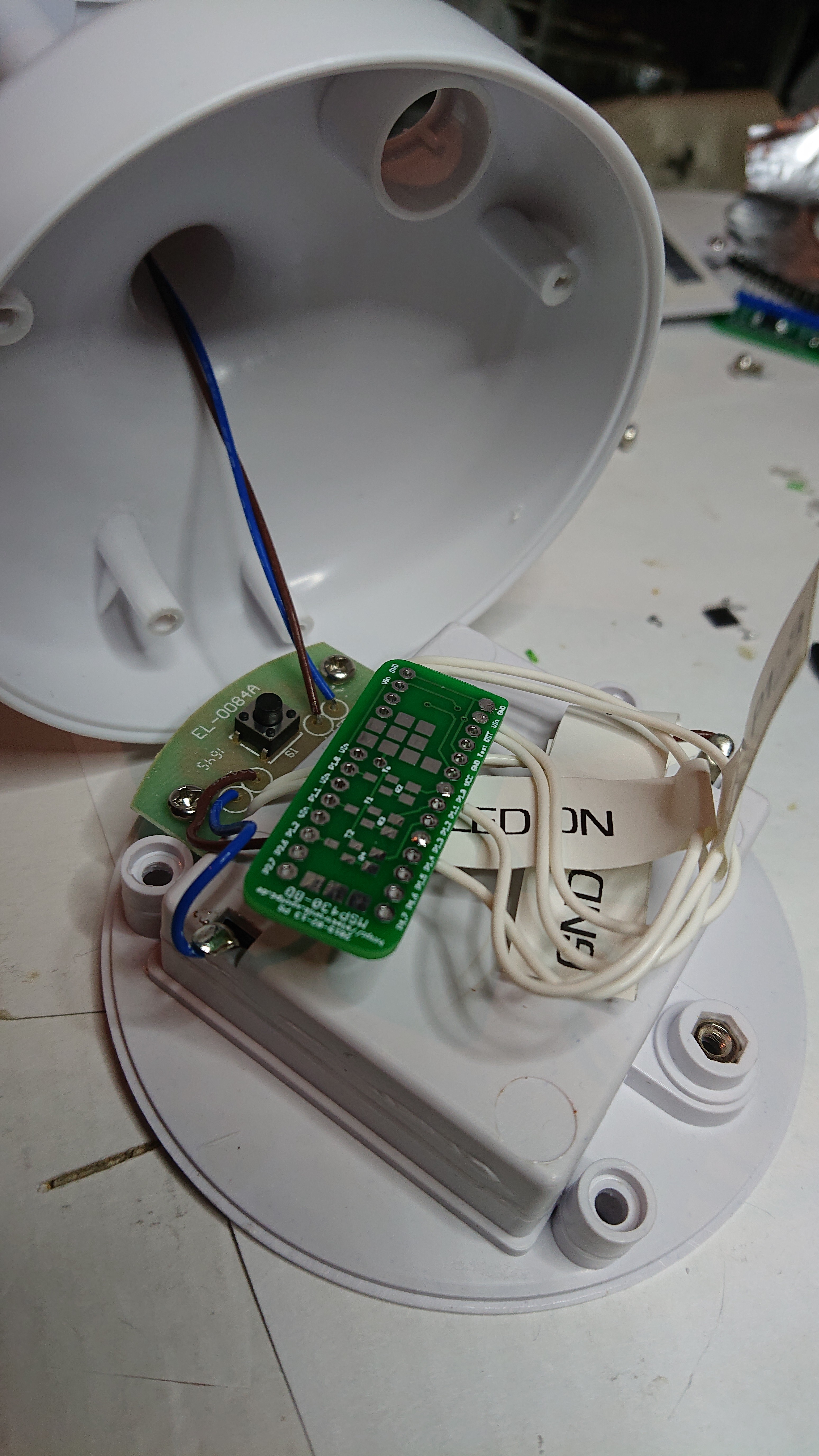
As I had luckily a MSP430 Launchpad and a custom MSP430 Breakout board laying around i thought I should give this one a Try. With the help of the Internet I created a really simple program.
- Initialize all GPIOs as INPUT_PULLUP to conserve energy
- Initialize 3 GPIOs as Outputs to control LEDs (I added additional 2 for Debug Purposes
- Attach Interrupt to One Input if the Voltage is pulled down.
- Start Loop
- Got to Sleep Mode 4 "LPM4;" (Further Reading: https://www.google.com/url?sa=t&rct=j&q=&esrc=s&source=web&cd=1&ved=2ahUKEwjn_NWFhbzgAhUMK1AKHT7rBsgQFjAAegQICRAC&url=http%3A%2F%2Fwww.ti.com%2Flit%2Fml%2Fslap124%2Fslap124.pdf&usg=AOvVaw021zLcgHdu-w02dCyaSlAe)
- If a falling etch is detected, wake up and continue main loop.
- If the Output is High, set it Low, if it is Low, set it High. (Toggle 3 Outputs with delays)
- Continue Loop
Its a really small programm. I added it to the project.
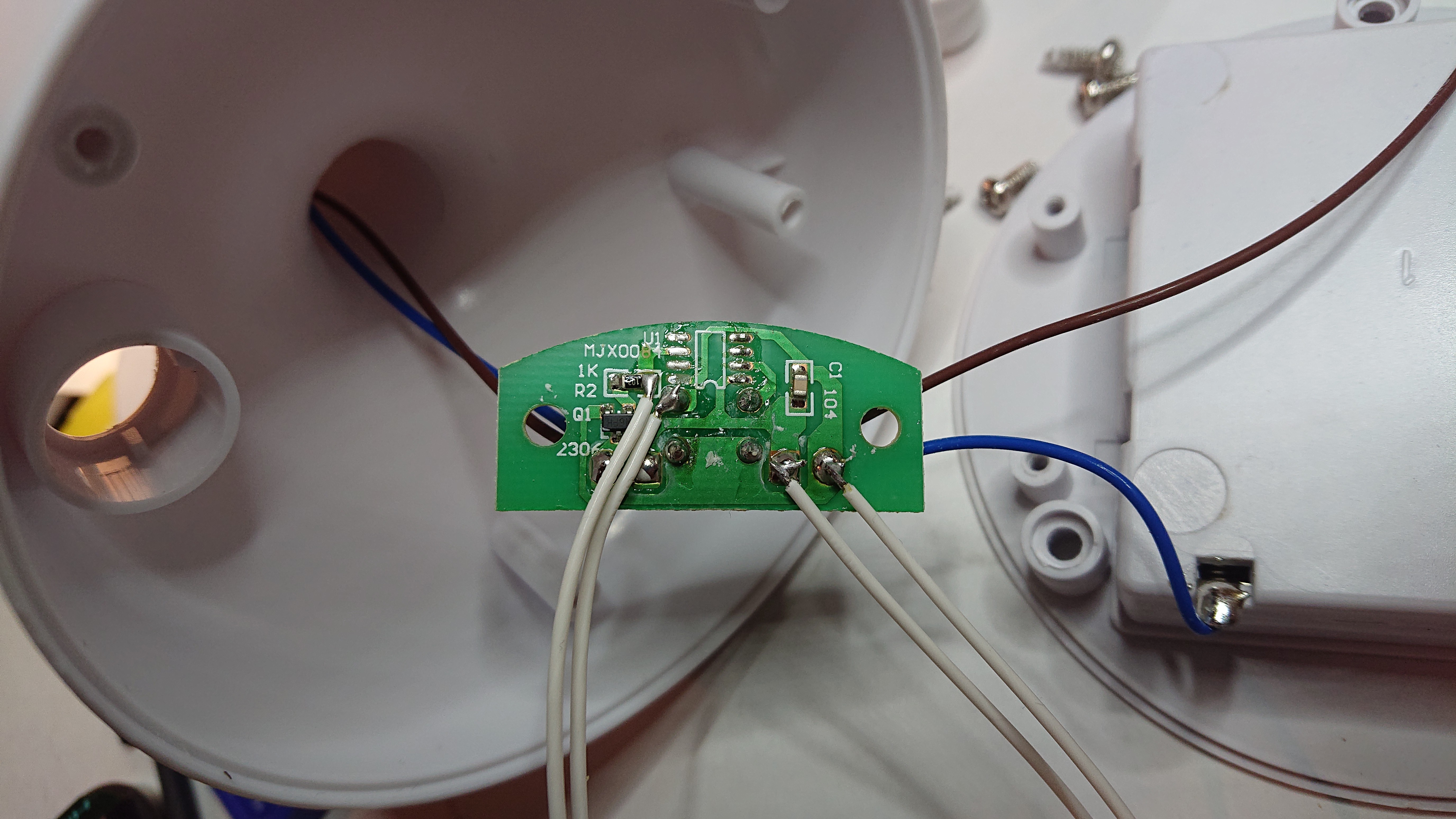
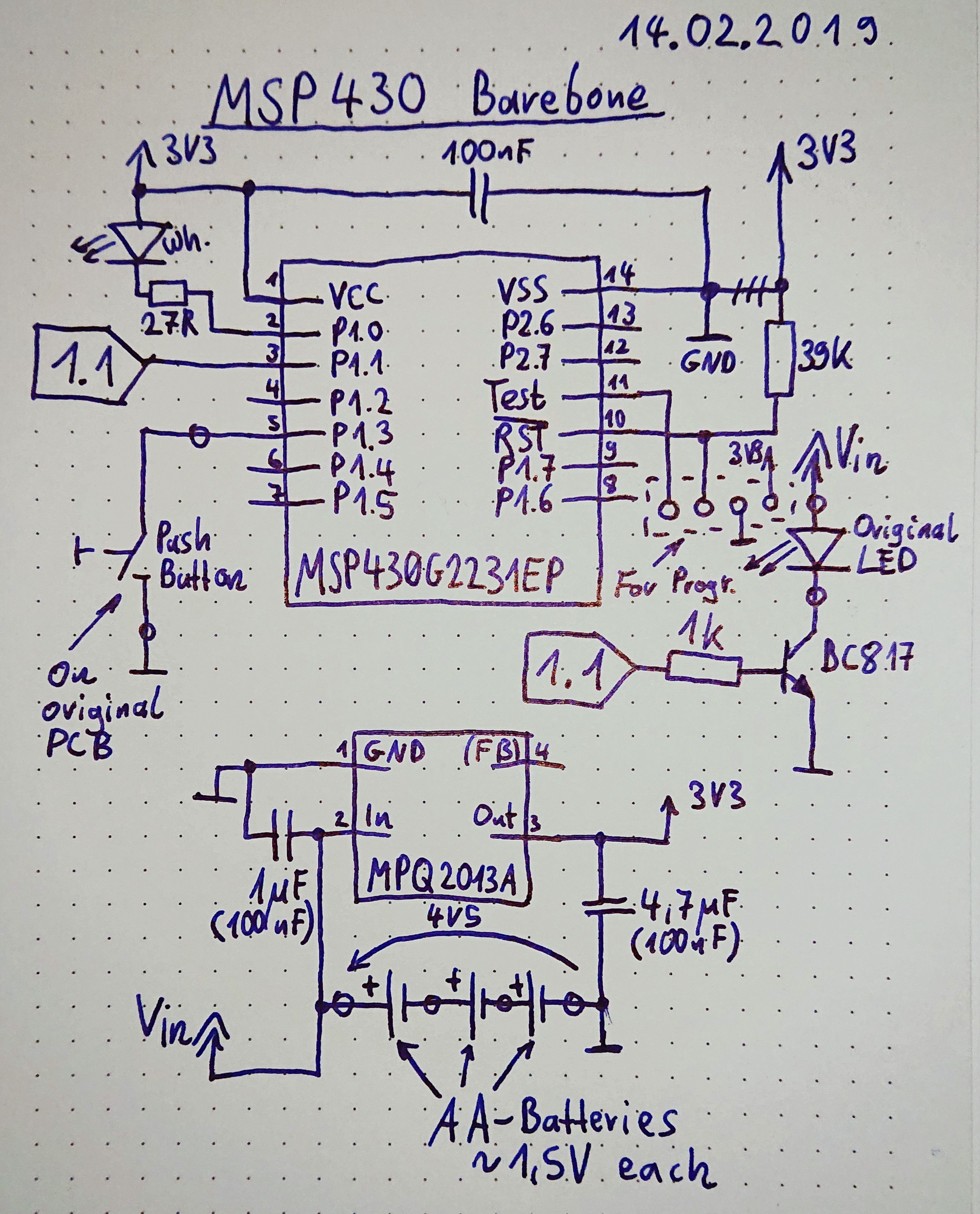
Here is a quick schematic (I added some circles on the attachement points to the lamp):
This circuit has a sleep current of ~ 4.5µA. (So i get hypothetically >60 years of Battery life. Since it is really likely, that the lamp might be on > 60h in the next 60 Years, it is a ok tradeoff (don't take the self discharge in account). The µC is capable of sleeping at ~ 0,5µA but the voltage regulator has a 3,3µA Quiscent Supply Current.
Here you can find a proof of concept (150x Speed):
-
3. Not that bad?
02/08/2019 at 22:26 • 0 commentsI thought about the Battery Life... If i assume that one cell holds 800mAh, 3 Cells hold 2400mAh.
So if the circuit draws 100µA the batteries would last 1.000 days???
So if the circuit draws 10µA the batteries would last 10.000 days (>27 Years) ???
If the circuit draws 100mA the batteries would last only 24h???
I'm still a bit sad, that the original Circuit draws 0.0µA ... so the batteries would last infinitely :-D...
-
2. Requirements
02/07/2019 at 22:18 • 0 commentsThe completed Project should fulfill the following Requirements:
- Working Voltage: 2,3V - 5V
- Shut Off Time: Infinite
- Sleep Current Average: < 10µA
- So in this Case 1 Minute of Light might (103mA * 1/60 = 1,7mAh) reduce the Idle Time by 2 days.
- WoF > 1 for completion
- The Design of the Lamp should not be altered to much
-
1. What have we got?
02/07/2019 at 22:05 • 0 commentsWhat we got is a small Batterypowered Table Lamp:
"Philips LED Tischleuchte, batteriebetrieben, tragbar, weiß [Energieklasse A+]"
- High quality LED light
- On / off switch on the product
- Automatic switch off after 15 minutes (Unwanted Feature!)
- Lightweight and portable for total flexibility
Battery operated - No cables or power outlet required (3x AA included)
- Scope of supply: Philips Moodlighting LED table lamp, white
From first view a lovely table lamp. But it is also very annoying, that it shuts down after only 15 Minutes.
I checked all components on the PCB:
- U1 MJX0084 or less likely MJXOO84 - it was long ago that i got that less results on google
- Q1 "2306" most probably: https://de.farnell.com/taiwan-semiconductor/tsm2306cx/mosfet-n-kanal-30v-3-5a-sot23/dp/1864577
- Drain: Connected to Battery -
- Source: Connected to LED-
- Gate: Connected to Pin 6 of U1 via R2 (1k)
- Push Button on PCB (THT)
- Connects Pin 2 of U1 to Battery - if pressed
R1 1k Most probably 0805 SMD
C1 Maybe 100nF?
- Connects Pin 2 of U1 to Battery - if pressed
- Battery (via cable): 3x AA Cell (4.8V) http://www.goldenpower.com/eco/en/product/carbon
- MODEL NUMBER GR6M
- NOMINAL VOLTAGE (V) 1.5
- DIMENSIONS (mm)
- Diameter: 14.0
- Height: 50.0
- AVERAGE WEIGHT (g) 16.5
- CROSS REFERENCE IEC: R6P ANSI: 15D JIS: R6P
- Since it might be a zinc–carbon (dry cell) .. AA batteries have around 400–900 milliampere hours capacity So assume 800mAh per Cell.
- LED(s) (via cable)
- Current ~ 102mA
- Voltage: ~ 4,8V
- Power: < 0,5W (Claims 0,57W)
- Apearance: Warmwhite
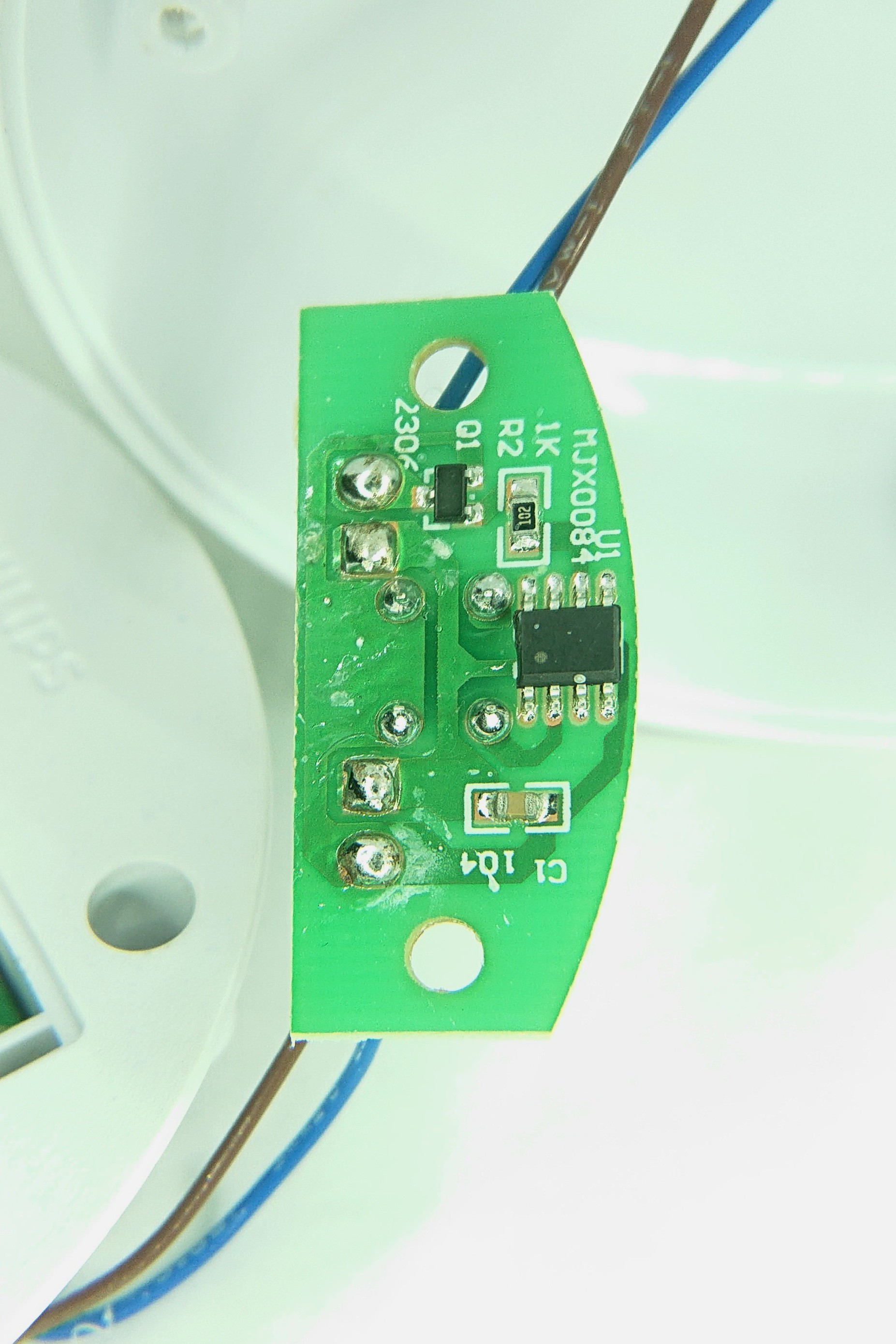
So the U1 is a "black box" there is AFAIK not much to do with the existing pcb.
The "Sleep Current" is about < 0,2µA @ 4,8V.
So there are some possible solutions:- Using of a physical On/Off Switch
- Pro: Really Easy
- Pro: Idle Power Consumption: ~0µA
- Con: Hard to gain a WAF > 1.
- Con: Outer Mechanics need to be Modified
- Con: Low Nerd Cred
- Using a CMOS circuit which toggles between On and Off
- Pro: May be easy to store it inside the lamp socket
- Pro: Its no black magic
- Con: Medium Nerd Cred
- Con: Power Consumption of > 8µA *.
- Using a MSP430
- Pro: High Nerd Cred
- Pro: Easy programmable Features (Can be adjusted later easily..)
- Pro: Can be made to turn on/off every Day
- Pro: Can be Made to turn off after a programmed time
- Pro: Can be extended to a general purpose pcb
- Pro: The LED could be PWM dimmed
- Con: Power Consumption in Power Save: ~8,5µA - 85µA* depending on Voltage
- Con: Needs a 3.3V Voltage Regulator
* Maybe there would be a possibility to enable the Power only after press of the Button?.. if not it would definitely break the energy rating (Battery Life).
I'm still open for further Ideas. Please let me know in the comments.