-
Flex Connector for Easier Device Assembly
01/18/2020 at 05:21 • 0 commentsJanuary 17, 2020
The Bin Level Monitor based on the VL53L0 has proven to be an ultra-low-power, accurate device for remotely keeping track of average fill level in a 1-meter-tall waste receptacle. But a long-standing problem with this device has been the need to mount the VL53L0 sensor on the case surface while the pcb is mounted on the case mounting posts; i.e, separately. So far I have been using small plated through-holes and soldered silcone-insulated wires between the pcbs. This works, and my one and only long-term test of the device used this method with success. But for a commercial device there needs to be a simpler (meaning cheaper) way to connect the two pcbs. I think I finally have the right design.
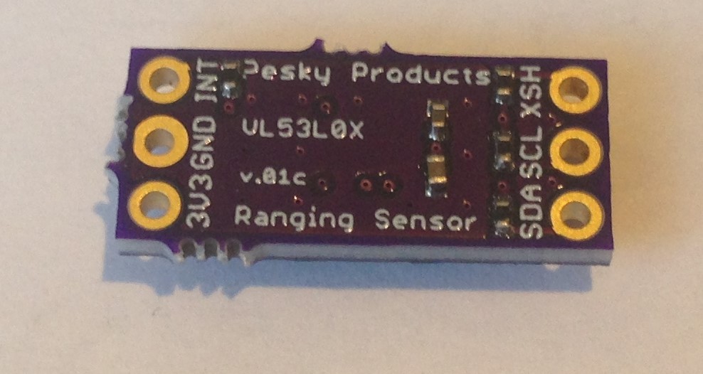
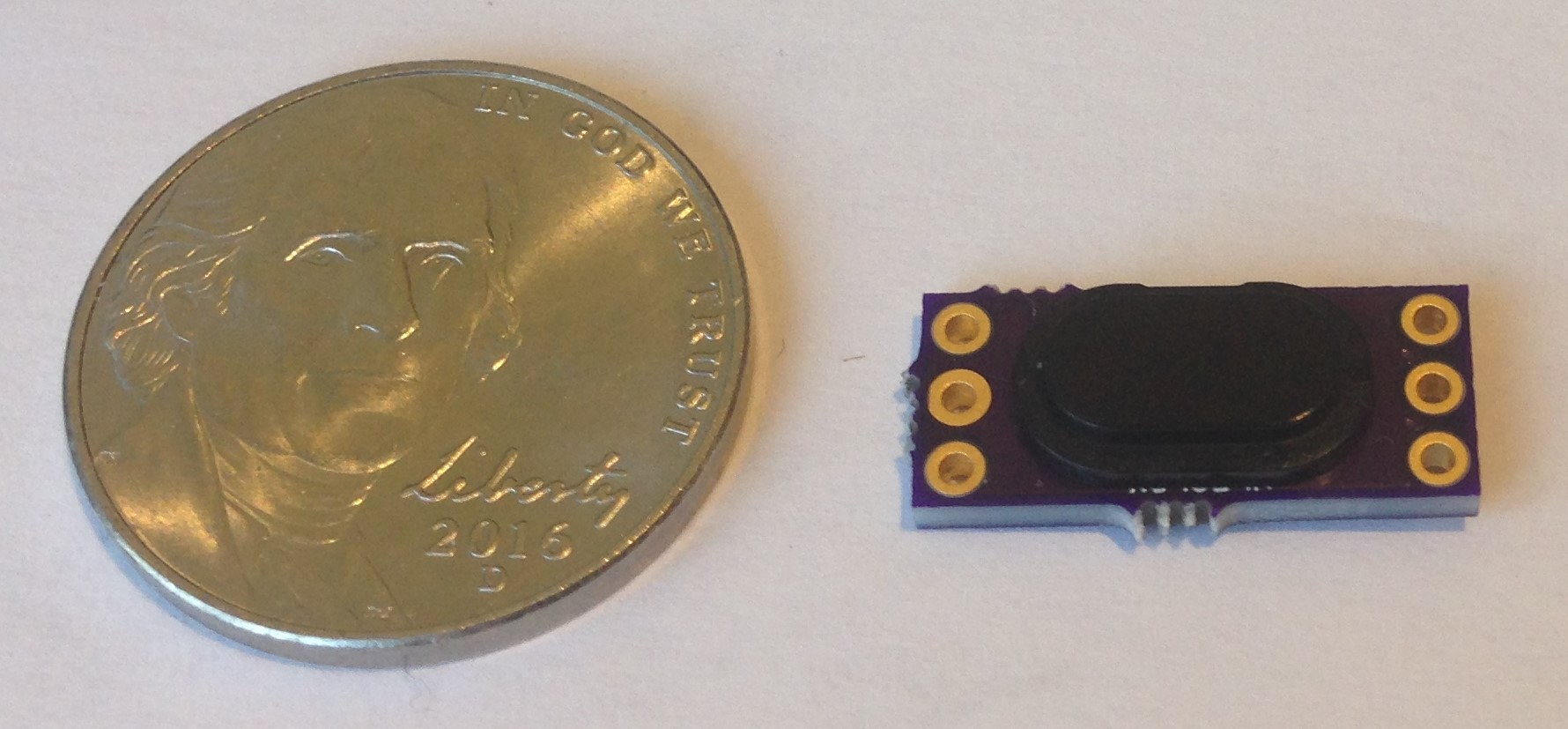
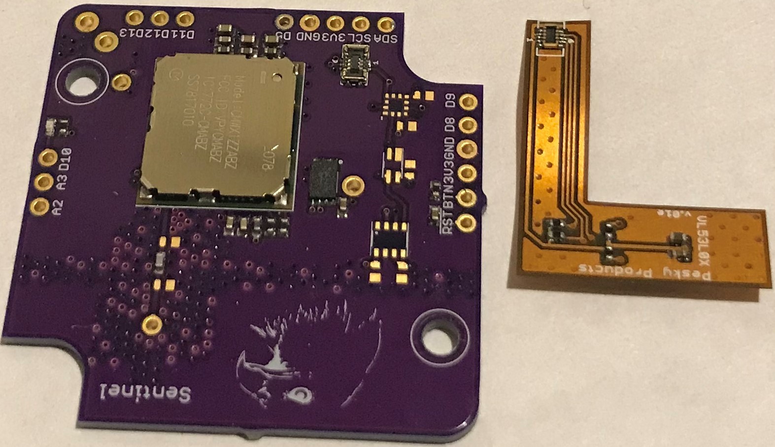
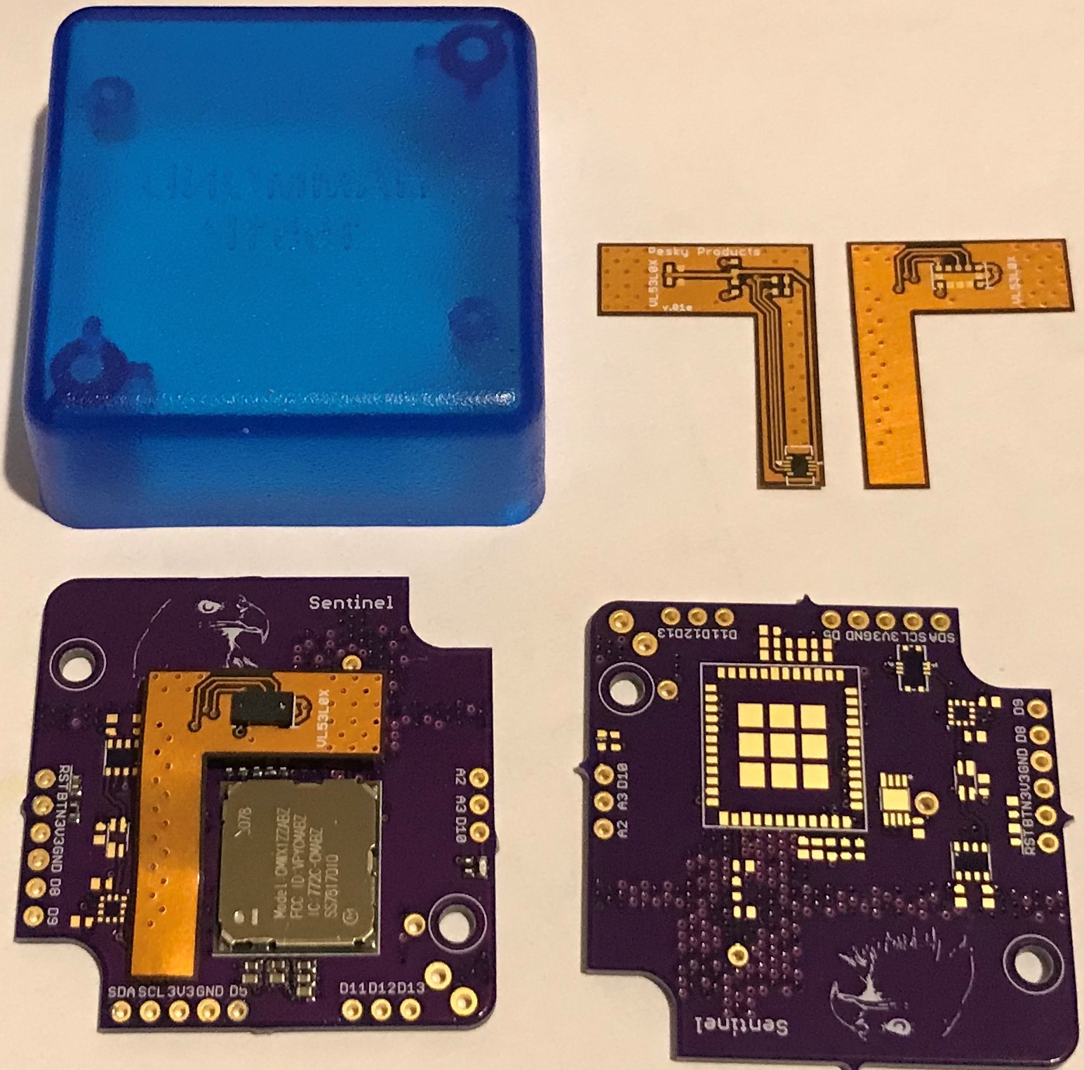
I redesigned the VL53L0 daughter board in flex and placed a small six-pin Molex flex connector at the end of a "dog leg" extension. With the corresponding mating connector on the main pcb, I worked out the geometry such that the VL53L0 daughter board could mount flush with the inside surface of the case as desired and simply "snap" into the main board. No more soldering individual wires.
![]()
It wasn't easy soldering these connectors, and I had to replace the one on the main board due to solder bridging on my first attempt. But in production this will all be handled by pick-and-place machines so the construction and design are what is important here. The BME280 pressure/humidity/temperature sensor, BMA400 accelerometer, and VEML6040 light sensor remain unpopulated in this build since I didn't really use these in the first trial.
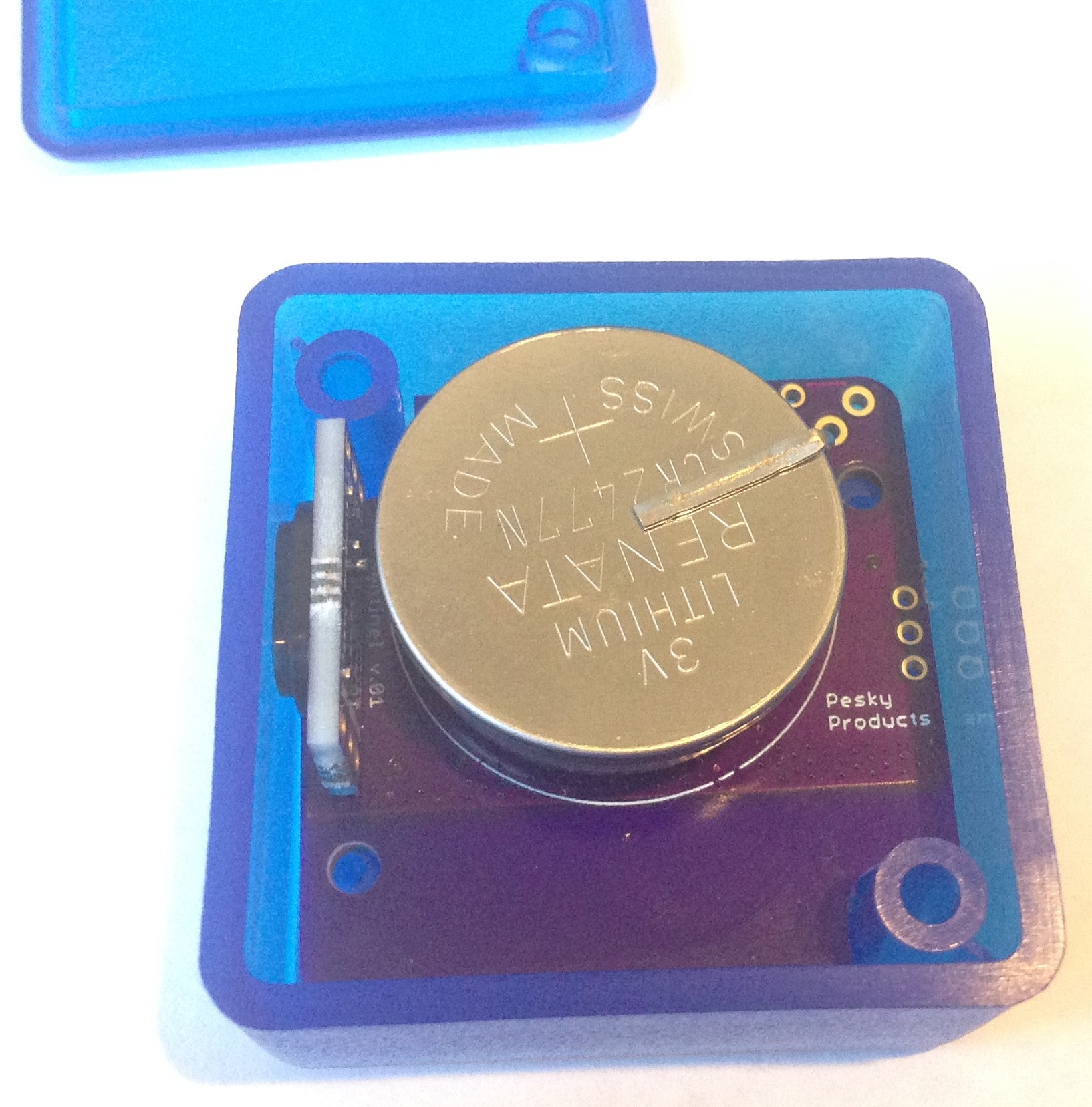
I am not sure how robust the connector is once mated. I might have to add a drop of glue in production to ensure a sound connection in the event the bin lid is slammed or the bin falls down, etc. This might not be an issue because the main pcb is screwed into the case and the daughter board is taped to the inside case surface, and there shouldn't be any possibility of relative motion between the two. But this is TBD.
![]()
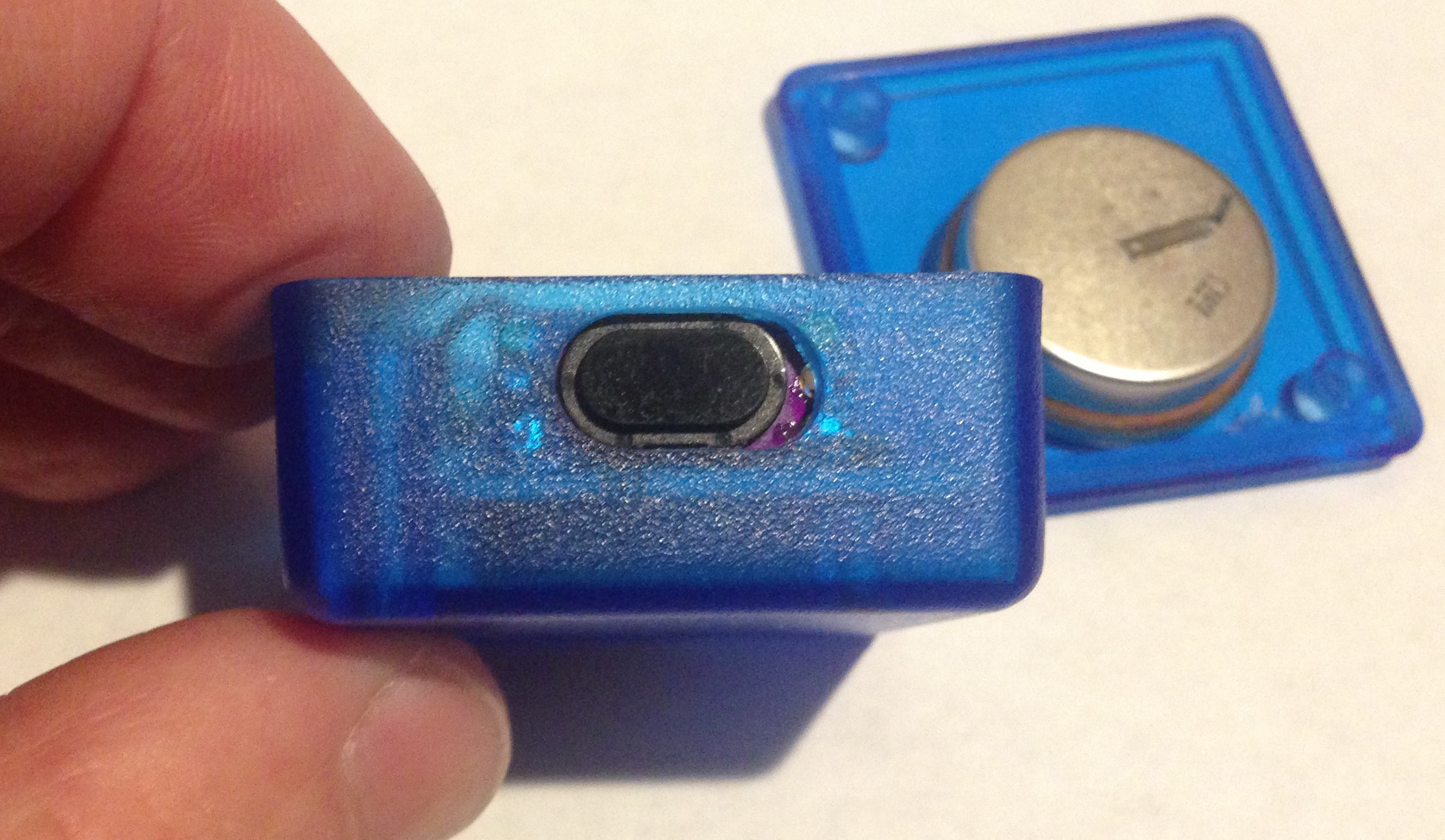
The length of the flex dog leg is the variable here since I am not sure what is the right length I need to fit into the well (still to be) machined into the bottom of the Hammond box. I want the beveled (the PMMA lens cover is beveled) penetration to lie right in the center of the box, and I will either have to bend to fit with the flex design I have or, possibly, shorten the dogleg a tad to comfortably fit into the well.
![]()
I asked my colleague Greg to machine one or two boxes for me and as soon as I get them from him I will assemble a complete unit, or at least try to do so. I think at worst I will have to tweak the design of the flex daughter board to optimize the length of the dogleg. But it looks like the design itself will work and will ease assembly in production as desired.
-
Cold Weather Fail
11/28/2019 at 00:48 • 0 commentsNovember 27, 2019
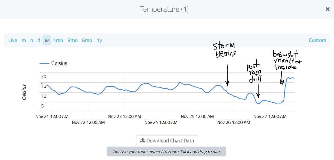
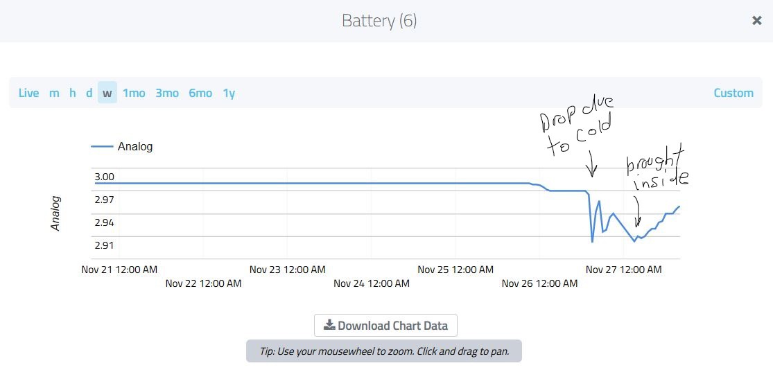
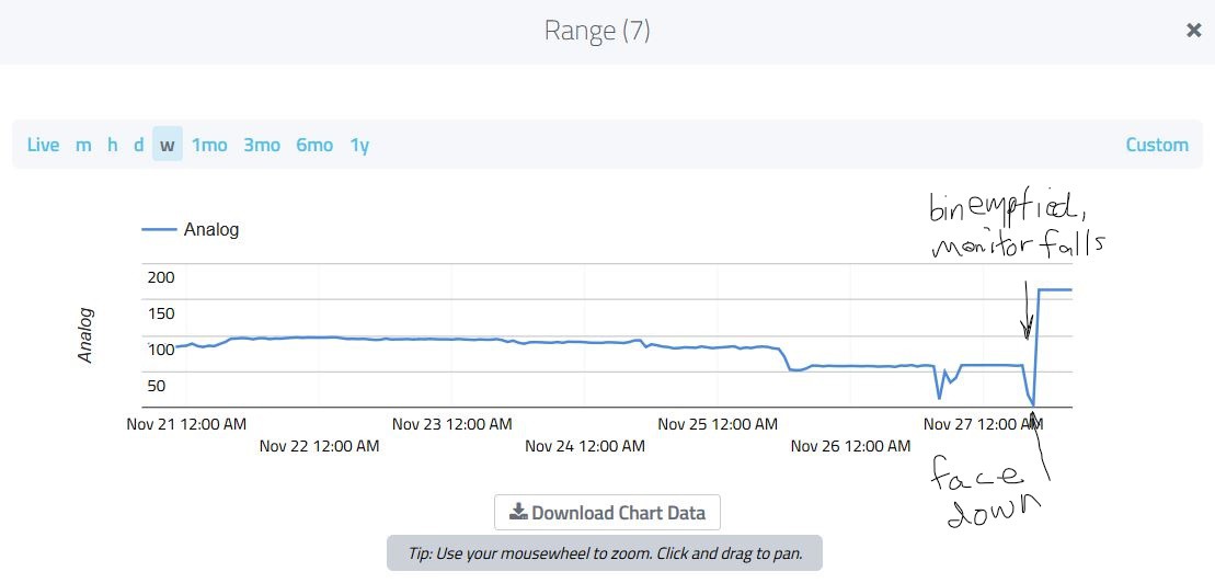
With the Arctic storm upon us just before Thanksgiving we got a blast of (for us) cold air that dropped temperatures into the low forties F (~5 C). This was enough, apparently, to loosen the VHB foam tape holding the Bin Level Monitor to the inside of the recycle bin lid such that when the recycle bin was emptied today, the monitor fell to the bin bottom.
![]()
Overnight low temperatures "plunge" from ~10 C to ~5 C with the Arctic storm.
![]()
Battery "feeling" the cold too, drops ~3% in voltage before warming up indoors.
![]()
Bin Monitor falls as a result of the garbage service emptying the bin and lands at the bin bottom, face (sensing side) down.
So the attachment method (very high bond tape), while lasting about 7.5 months (~30 bin emptyings), didn't stand up to cold weather. The Bin Monitor, however, kept going and is still going. I am just lucky the device stayed in the bin and isn't on its way to the local recycling center!
I think I will keep this going for as long as it will continue in order to get a measure of the battery life in service.
The next step would be to design a custom case that would allow more secure attachment of the device to the inside bin lid.
Also, for larger volume production, some means for more easily connecting the VL53L0 daughter board to the main pcb would be useful. Maybe Molex PICO Blade connectors (cheap) or flex connector (expensive). Maybe there is a way to redesign both pcbs so that they fit together (interlocking?) so that connectors can be avoided altogether.
Bottom line: this Bin Level Monitor seems to have the robustness (modulo attachment) and low-power usage to make a commercial product. Just need to make the transition from prototype to finished product...and find some customers!
-
At the Six-Month Mark
10/12/2019 at 19:08 • 0 commentsOctober 12, 2019
My son didn't make much progress over the Summer on the 3D-printed container. Oh well...
I have been ignoring this Bin Level Monitor as usual but decided to take a look at what is just after the six month mark after deployment. Is it still working?
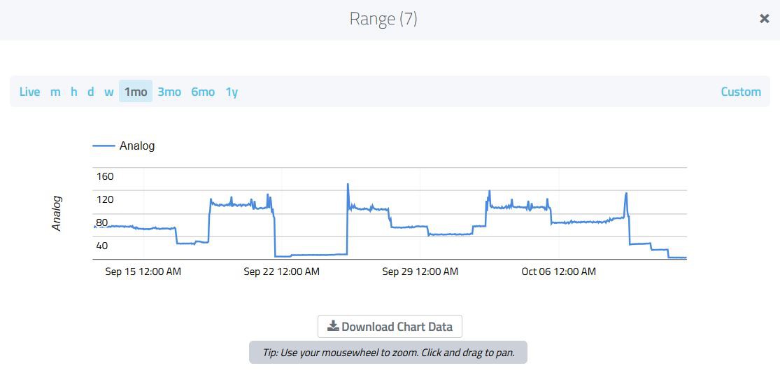
This is the bin level record over the last month:
![]()
showing that 1) the Bin Level Monitor is still ticking and 2) the record of fill level remains more or less accurate.
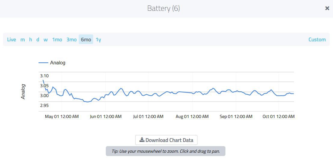
Here is the battery level over the last six months:
![]()
So after a little bit of settling at the beginning of deployment the battery voltage has been relatively constant at 3.0 V within a percent or so over the last five months with no indication of ageing or dissipation. How long will this 950 mAH coin cell battery last? I'll let you know...
-
At the 3-Month Mark
07/17/2019 at 18:25 • 0 comments17 July 2019
I haven't been doing much with this project except collecting data from my one and only prototype currently living under the lid of my recycling can. I placed it there in April and was happy it survived its maiden pickup. Since then I have mostly ignored it. Well, today I finally took a look on CayenneLPP and this is what I found:
![]()
Not great resolution but you can see 1) the device has been continuously operating for about three months, 2) it is more or less recording fill level (in millimeters, but this might as well be percent for a 100 mm deep bin!), and 3) it has survived about a dozen pickup events where the bin is clutched by steel arms, hoisted up from the ground, dumped upside down, then dropped on the ground again. Yay for VHB foam tape!
Here is the record over the last one month for better resolution:
![]()
I have marked the last four pickup events by hand in red (we missed the one on July 3). I am still getting excursions when the bin is empty above the 100 mm mark due to both high temperatures when the bin lid is exposed to the sun and inherent inaccuracy in the VL53L0 due to the low-power (i.e., fast) setting I had chosen rather than perhaps a more appropriate high-accuracy setting. Still, this record is clearly capturing the instantaneous fill level of the bin. In particular, it shows that the bin often gets more or less full days before the pickup. This kind of information could be used to adjust the pickup times; in this case more often than once a week is indicated.
Of course, I recorded other environmental information (last month shown):
![]()
![]()
![]()
temperature (top), pressure (middle), and humidity (bottom). Also battery voltage and lux from the light sensor, but none of these are as interesting as the bin level itself.
Next step is to have my 15-year-old son design a 3D-printed case for the bin level monitor. The Hammond case works well but required "subtractive" machining to make the well for the VL53L0 + window assembly. I am wondering if I couldn't have an inexpensive 3D-printed lid made for the Hammond box that would allow quick assembly of dozens of these bin level monitors so I might offer them for sale as a complete device. I'll report on this next time.
-
Monitor Survives Pickup
04/25/2019 at 00:12 • 0 comments04/24/2019
Today was trash day and the first test of how the Bin Level Monitor performs under the stress of the recycle bin being emptied and whether it would survive. I am happy to report that it did survive, and offered a surprise as well.
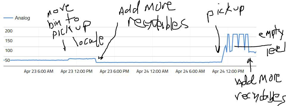
First (most of ) the range record since I redeployed the Bin Level Monitor after the modifications from the last log:
![]()
Not much happened while I occasionally added recyclables to the bin over the course of about two days. The bin was already about 2/3 full (at ~40 mm) when I reinstalled the Bin Level Monitor and dropped to about 30 mm as I added more recyclables. When I moved the recycle bin from just outside the garage to the top of the driveway the day before pickup there seemed to be some settling of the contents because the range increased by 10 mm or so. I added more recyclables and the level dropped again to about 20 mm. On pickup and emptying the range shot up first to 63 mm and then to 93 mm and seemed to stabilize. The recycle bin is about 1 meter deep so this seemed reasonable. To my surprise I started getting very large range values of 150 mm and quite a few pegged at 163.74 mm exactly.
There are two possible things happening here. One is since the Bin Level Monitor is mounted on the underside of the lid it sees more or less direct sun and heats up quite a bit, at least for a short part of the day, maybe two hours. This time coincided with the odd oscillations between a more or less correct ~100 mm range reading and the much larger values. Secondly, I have the VL53L0 set in high-speed mode://#define LONG_RANGE // choose to get longer range at the expense of accuracy #define HIGH_SPEED // choose to get faster speed at the expense of accuracy but lowest power //#define HIGH_ACCURACY // high accuracy but high powerand I am also using forced mode to save power. Forced mode means the VL53L0 wakes from sleep, takes one measurement using a 20 ms integration time and then goes back to sleep. These settings produce range measurements at the very edge of acceptable accuracy in order to minimize power usage and it is not surprising that at 1 meter distance from a dirty, sticky plastic surface the VL53L0 is having trouble getting an accurate range. Adding some recyclable copy and news paper and such seems to have resulted in a stable range at about 70 cm. So I think this is not a temperature issue per se but rather that I am operating the VL53L0X at the limit of its ability. I suppose the easiest thing to do would be to set an upper limit of 100 mm to the reported range, since I do not want to increase the integration time or change to a more accurate measurement mode.
Overall, I would say the Bin Level Monitor is doing what it is supposed to do. I will just let it run now, since it should last months if not years on the 950 mAH coin cell battery. In a month or so I will report on the data to see if there is anything surprising about what the Bin Level Monitor records. In the meantime, I have a nice indicator of when the weekly recycle bin collection takes place, at least at a ten minute time resolution.
Addendum: Just a sanity check.
![]() the Bin Level Monitor is still chugging away. Next update in a week.
the Bin Level Monitor is still chugging away. Next update in a week. -
Top Mounting
04/21/2019 at 17:28 • 0 comments04/21/2019
Well I tried various side mounting schemes and after a lot of fussing decided that top mounting (like here) is really the way to go with such a small box. The problem is that the PMMA window designed to mount over the VL53L0 ranging sensor has a step to allow flush mounting to the outside case and to allow gluing or sealing along this stepped edge for a more or less hermetic seal.
![]() Machining such a complicated shape onto the side of the box proved impossible. But doing so on the box bottom was relatively easy (see above, thank you Greg Tomasch!). I also redesigned the VL53L0 carrier board using a 2-layer design so I could have it made at OSH Park in 0.8-mm thickness and I reduced the width a bit thinking it would be easier for side mounting. The pcb width is now the same as the PMMA window width. The PTHs are designed to be aligned with those on the main board as I was thinking I could use some sort of board-to-board mezzanine connector with the side mounting but I have fallen back to simply soldering wires.
Machining such a complicated shape onto the side of the box proved impossible. But doing so on the box bottom was relatively easy (see above, thank you Greg Tomasch!). I also redesigned the VL53L0 carrier board using a 2-layer design so I could have it made at OSH Park in 0.8-mm thickness and I reduced the width a bit thinking it would be easier for side mounting. The pcb width is now the same as the PMMA window width. The PTHs are designed to be aligned with those on the main board as I was thinking I could use some sort of board-to-board mezzanine connector with the side mounting but I have fallen back to simply soldering wires.
I did test the new window location with the old rig by taping the carrier board over its top to hold it in place (the fit is pretty snug though) and placing the main board in its usual place. The main board and carrier board nearly interfere so switching to the thinner carrier board design is really a must for bottom mounting. Although I could stand the main pcb off with washers or something.
I ran the test a few days with the device mounted to the underside of the recycle bin lid and got this:![]() The nice thing about this is that the range is correct; the ranging sensor points straight down and sees whatever happens to be in the middle of the bin. I added some material to the bin a few times over the course of the two days and the bin level dropped from ~60 cm to ~46 cm and then to 42 cm, etc. So the main function appears to work well. I also recorded temperature, pressure, humidity, ambient light level and acceleration (really orientation of the bin lid). So all worked as it should have.
The nice thing about this is that the range is correct; the ranging sensor points straight down and sees whatever happens to be in the middle of the bin. I added some material to the bin a few times over the course of the two days and the bin level dropped from ~60 cm to ~46 cm and then to 42 cm, etc. So the main function appears to work well. I also recorded temperature, pressure, humidity, ambient light level and acceleration (really orientation of the bin lid). So all worked as it should have.
One problem I had was that when I opened the lid the device would often reset as denoted by gaps in the record. This happened because I didn't solder the coin cell battery to the pcb. So when I opened the lid the battery connection would often fail, power would be interrupted and then sometime later would be re-established and the device would reset and start reporting again. At least, this is what I think was happening. I am going to repeat the test over a longer term using the new VL53L0 carrier board and with the coin cell battery soldered to the main pcb to see if I can get weeks or months of continuous record. I am also curious as to whether the device mounting with VHB foam tape will survive the weekly bin emptying by the garbage service. We'll see....
Addendum: I replaced the VL53L0 carrier board and soldered the coin cell battery onto the main board and put everything together:![]() I am holding the carrier board to the case with double-sided tape, the main board is screwed into the two case mounting holes as before and with the coin cell battery soldered to the main board the package is reasonably rugged and without jitter. A little pre-deployment bench testing to make sure all is working then out to the bin lid it goes. After a few weeks of real-world bin monitoring I will report results...
I am holding the carrier board to the case with double-sided tape, the main board is screwed into the two case mounting holes as before and with the coin cell battery soldered to the main board the package is reasonably rugged and without jitter. A little pre-deployment bench testing to make sure all is working then out to the bin lid it goes. After a few weeks of real-world bin monitoring I will report results... -
Real World Test
03/19/2019 at 01:34 • 0 comments18 March 2019
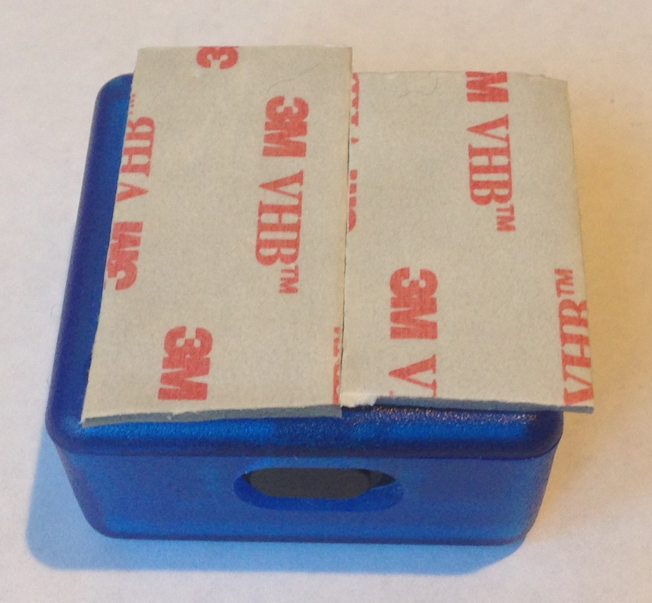
Gulp! After a night sitting peacefully on my kitchen table measuring the distance to the window I put very-high-bond foam tape on the back of the Bin Level Monitor prototype
![]()
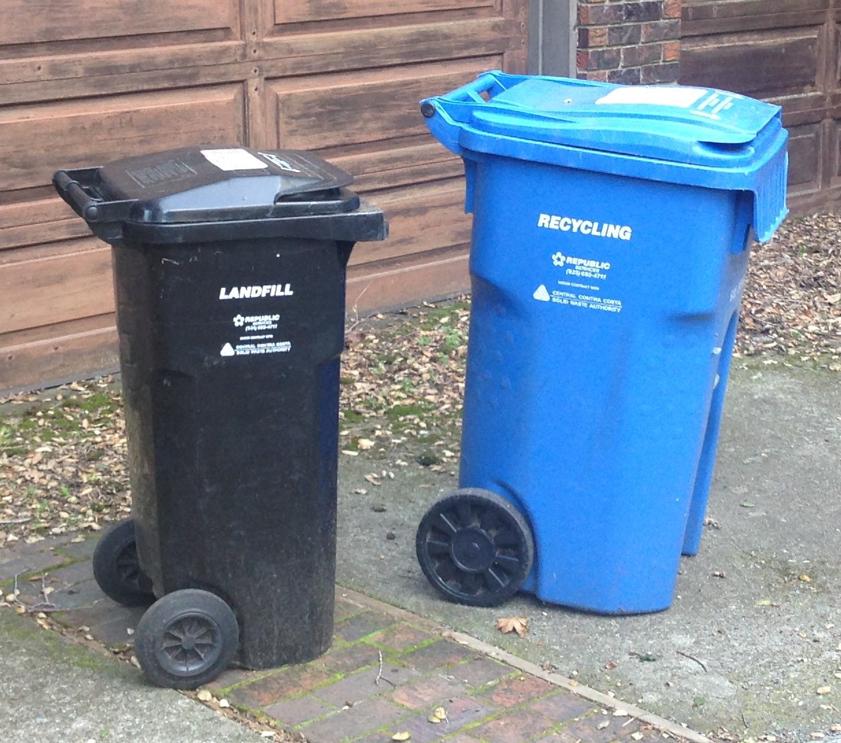
stalked the unsuspecting garbage and recycling cans sitting in the front of our house
![]()
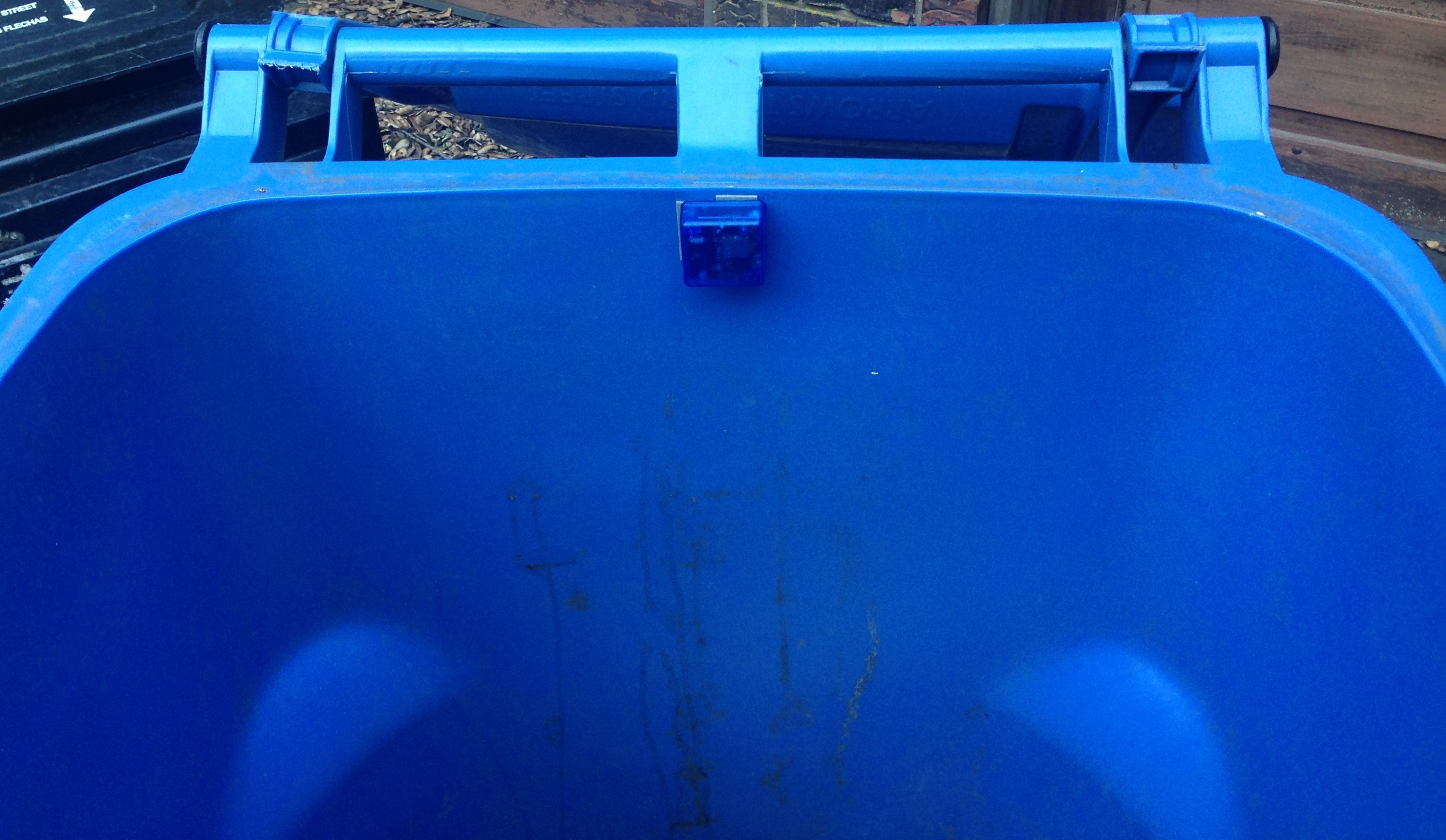
and rudely pressed the Bin Level Monitor on the upper inner portion of the blue recycling can after wiping a bit of the accumulated dirt off of the spot with a paper towel.
![]()
I pressed and jiggled so hard to be sure of firm attachment that the device reset; I saw the blue led come on as part of the initialization routine. I didn't solder the coin cell battery onto the main pcb like I probably should have, relying instead on a small piece of foam to apply enough pressure to make good contact. Well my jiggling must have worked it loose for a moment because the device reset. I know this because in the first report the acceleration is again showing all zeroes (mostly) indicating the offset biases were calculated in the vertical position.
The good news is I am getting data from all sensors. The range is fluctuating between 11 and 14 cm, which seems rather low. There are some things already in the recycle bin but I would have expected more like 30 cm. I suppose I should go out and measure the depth to be sure. Perhaps I am only seeing the range from the device to the side of the container.
Well, one big test is Wednesday --- trash day! I will let the recycling pickup occur as usual with the Bin Level Monitor installed and see what kind of signals I get and whether the device survives the ordeal.
Update: OK, went to check, and the recycle range should be closer to 35 or 40 cm. Turns out in my efforts to press hard on the device a finger pushed the VL53L0 out of its little hole (also not glued as it should be). So I removed the whole kit, straightened the VL53L0X, let the device configure while lying flat to get the accel right, and reinstalled. And...the range is still reading 12 cm...not sure what is going on here. More to come...
-
Power Testing
03/18/2019 at 02:58 • 0 comments17 March 2019
I took the plunge and used my drill bits and round file and made a hole in one of the Hammond boxes that the lens cover and VL53L0 could mount into.
![]()
![]()
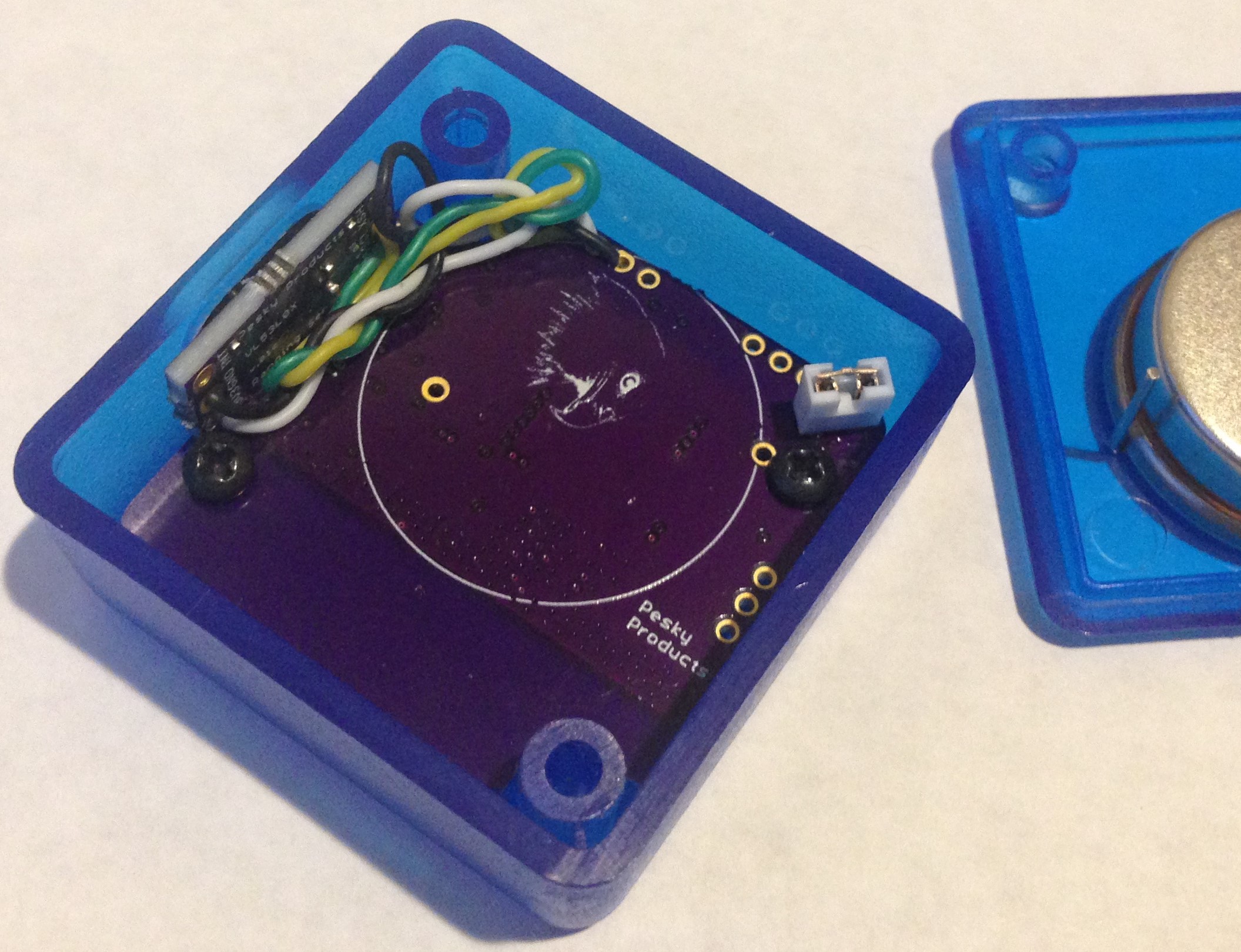
Not great, but it will do. I soldered 30 gauge-silicone-insulated wires between the VL53L0 daughter pcb and the main board, deciding that just 3V3, GND, SDA, and SCL were enough since: 1) using hardware shutdown only saves ~1 uA over software shutdown and 2) it takes time to initialize the VL53L0 when exiting hardware shutdown whereas the latency for software shutdown is quite low, and 3) I am using one-shot measurement, no real need for a data ready interrupt here. I should have moved the hole over to the left another 100 microns since there is a tiny interference between the VL53L0 pcb and the mounting screw for the main board. Nothing serious though. And I used too long wire length, so I ended up with a bunch of wire I have to tuck into a corner. Overall, this works. But on the next iteration I need a better scheme for board-to-board connections!
![]()
The white jumper is a poor man's switch. It connects the coin cell battery anode with board power, so I just need to install the battery and close the jumper to turn on the device.
I modified an existing program specifically for the Bin Level Monitoring application. The basic architecture is to configure all of the sensors and LoRaWAN parameters, and create timer callbacks in the setup function. Then in the main loop everything is based on an interrupt-triggered flag and the default state is MCU in deep sleep (STOP) mode until something happens to wake it up. This can be a sensor interrupt, an RTC alarm interrupt or timer interrupt. Here I am using the BMA400 interrupts set for wake-on-motion and sleep-on-no-motion. So flags are set whenever these interrupts trigger, but I am not really using these for anything yet. I could use a simple counter to display the number of times the BMA400 detects a wake condition as a bin collision indicator, or simply keep track of the number of times and when the bin has been moved. This is still TBD.
I am using the single measurement modes of the BME280 and VL53L0 and I am manually measuring the ambient light with the VEML6040 by enabling the sensor, waiting the integration time, and then disabling before reading the RGBW data. I tried to use the trigger mode for single meaurement but I didn't get this to work at first. I will have to work this out on the breadboard where programming is more convenient.
The idea is to set two timers, one for LoRaWAN and one for reading all of the sensors. These could have different duty cycles in the case the sensor data is to be logged, for example. But in this case, there is no SPI flash on the board, so I set them both to either one minute or ten minute intervals, the latter is the likely setting for actual use in monitoring bin level.
When the sensor timer triggers, the readSensors flag is set to TRUE in the callback, the MCU is woken up, and the main loop executes. When the main loop gets to the if(readSensors == TRUE) test, the main loop enters the section where all of the sensor data is read. I have this timed to occur two seconds before the LoRaWAN timer triggers an interrupt. If there is no other business to attend to the MCU goes back to sleep and waits for another event.
When the LoRaWAN timer triggers, the callback constructs the LoRaWAN data packet from the last data entries and sends it. The MCU wakes from sleep just long enough for the LoRaWAN modem to operate and then returns to sleep. I am using CayenneLPP protocol to send the data so it can be conveniently displayed on the myDevices dashboard.
![]()
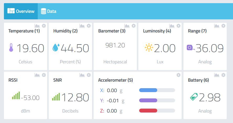
Fortunately, everything works. The range is in cm, battery level in Volts. I am measuring ambient light through the blue translucent box. I think the accelerometer is reading zeroes because I calibrated offset biases with the device standing vertical instead of flat as the function expects. This dashboard is from one of the power tests on my workbench, where I used ST's X-Nucleo-LPM01 to measure average current usage at 3.0 V power input.
I ran two power tests for a total of either one or two hours. The first test with the sensor read and LoraWAN Tx duty cycles at one minute and the second test at ten minute intervals. At one minute duty cycle, the average current usage after one hour run time was 174 uA and the sleep current (when the MCU is in STOP mode and all sensors are at standby) was 7.2 uA. Obviously, the average current is going to depend on the duty cycle. At ten minute duty cycle, I measured 37 uA average current usage after one hour and 30 uA after two hours. I expected (174 - 7)/10 + 7 uA ~24 uA since the ten-minute-duty-cycle case should use ~1/10th the power of the one-minute case. And maybe when averaging over even longer times that is what I would measure, but I got tired of waiting...
So let's just say that at ten minute duty cycle, the average current usage is less than 30 uA. Then the 950 mAH coin cell battery should last at least 950 mAH/(0.03 mA x 24 H/day) ~ 1319 days or 3.6 years.
Well, maybe a one week real-world test in an actual bin would be in order before we get too carried away....
-
First Build
03/16/2019 at 23:02 • 0 comments16 March 2019
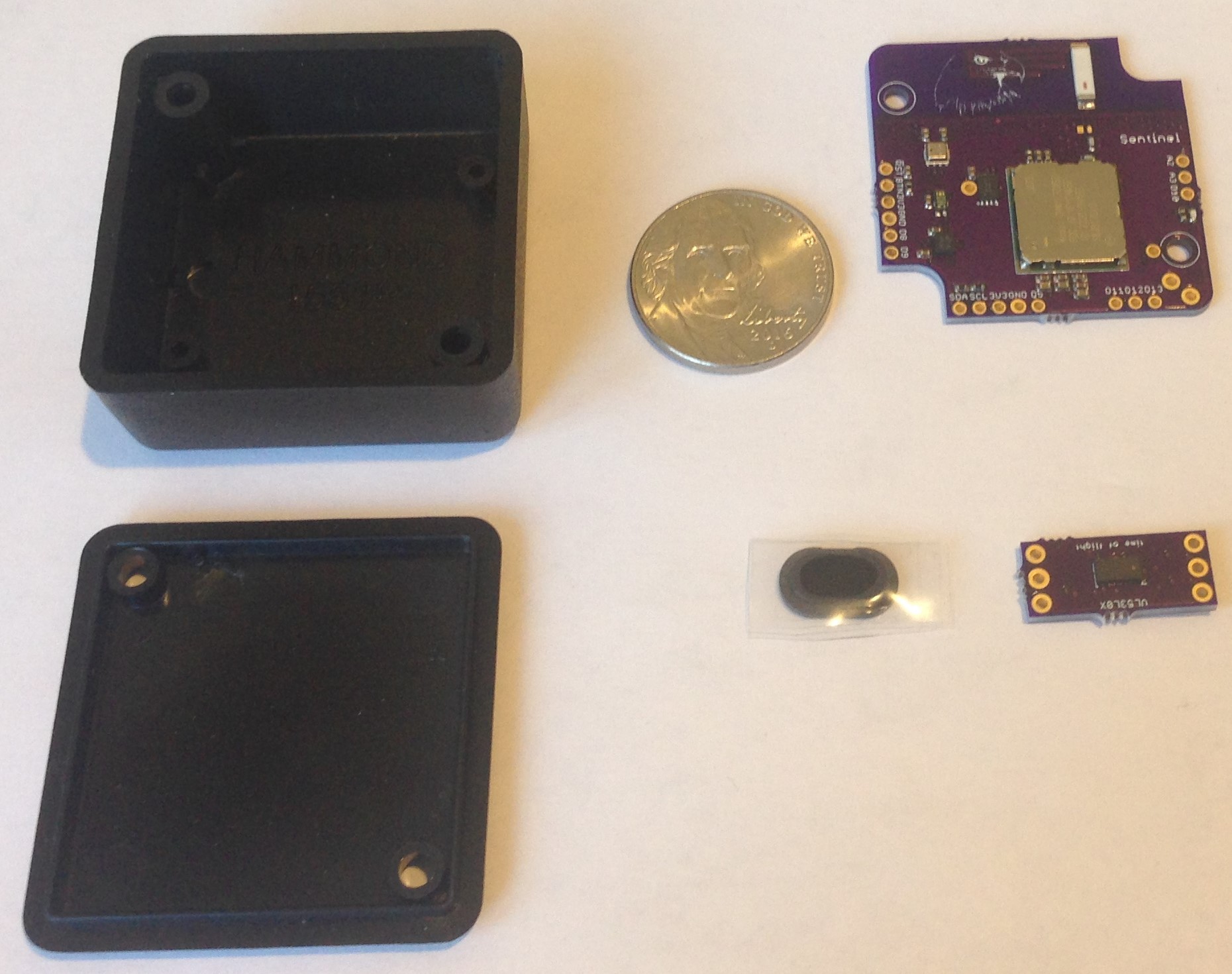
I received the pcbs for the first design iteration yesterday and was pleasantly surprised to see that they fit into the small 1551P Hammond box just as desired. There are actually two pcbs; one main board for the CMWX1ZZABZ-078 host MCU and LoRaWAN modem and one for the VL53L0 time-of-flight ranging sensor. It took me an hour to assemble these with no problems encountered. Let's take the tour--here is the total kit (US nickel for size comparison):
![]()
the pcb fit into the box-with the holes aligned properly!
![]()
and a close up of the main pcb:
![]()
I assembled all three of the auxiliary sensors; the BME280 for inside temperature and humidity measurement; the VEML6040 ambient light sensor for open lid detection; and the BMA400 accelerometer for movement /tip detection. There is a secure EEPROM for key storage, secure boot, and secure FOTA, etc. Programming is via SWD on D8/9; I use a $4 ST LINK V2 I bought from e-bay. The daughter VL53L0 pcb will connect via wire to the five-pin SDA/SCL/3V3/GND/D5 port where the last is for the VL53L0 interrupt. I exposed a UART port for debugging on A2/A3 and an SPI port just in case I want to add an SPI flash or SD card or display, etc. I am using a LoRaWAN chip antenna similar in design to what I use on the Grasshopper development board. Lastly, there is a blue led on D10, which helps with debugging and gives a visual indication of a "heartbeat" when the program is running normally.
The daughter pcb holds the VL53L0, and is similar to the breakout board I have been selling on Tindie for years. I just put the passives on the back to allow the PMMA ("glass") lens cover (black object wrapped in plastic) to be attached. The lens cover comes with adhesive on the back and is intended for easy mounting onto the pcb resulting in just the right air gap for protected ranging to the outside.
![]()
![]()
![]()
The challenge, at least for me, is to mill the proper holes into the side of the plastic box to allow proper mounting of the daughter board. I might hack away with drill bits and file to see what I can do by hand, but fortunately for me, I have a friend with a well-equipped machine shop who will make short work of this task for me. I might choose to butcher one of the boxes until I can get a few made properly as time permits.
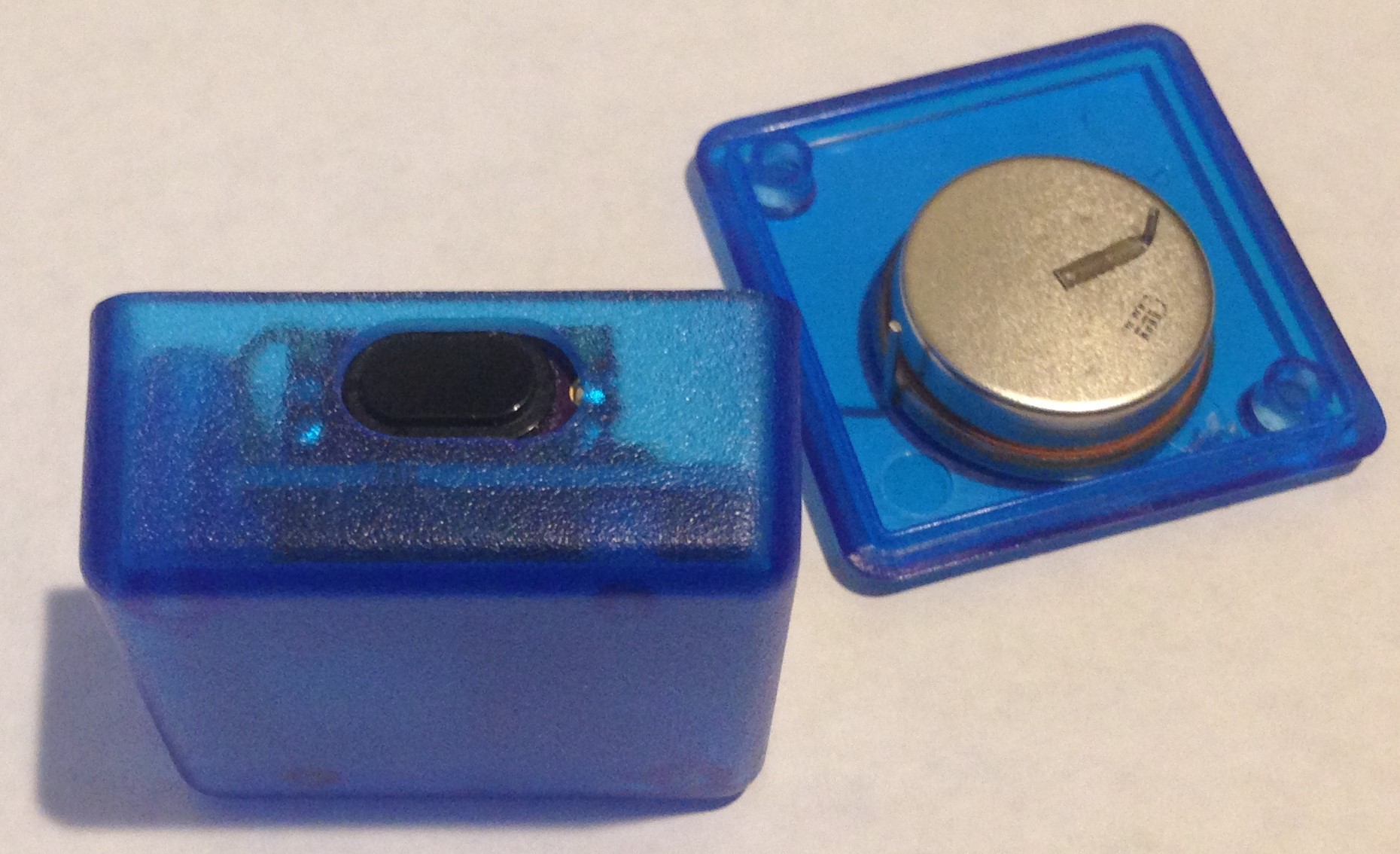
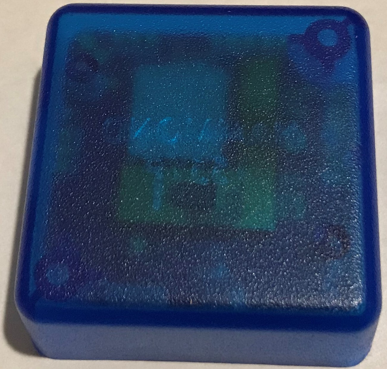
I really would like a transparent box but I found the next best thing: translucent blue!
![]()
This will allow me to see not only the blue led as it blinks every minute or so to let me know all is well, but it will allow the ambient light sensor to detect when the bin lid is opened without requiring penetrations into the box that could be fouled with bin "debris".
I will need some kind of penetration to allow for pressure equilibration and sensible humidity measurements. I plan to use my smallest (1 mm) drill bit to make a hole in the bottom-facing box side (to the left in the above image) and then cover the hole on the inside with a small porex adhesive filter patch that will at least allow pressure equilibration. I am not sure yet whether accurate humidity can be measured with this set up. The Hammond box closes up pretty tightly but the cover is not strictly water proof. But my hope is that the box cover secured with screws will keep all but the muckiest muck out of the box.
Next steps: 1) Arduino program development, 2) power usage testing, 3) function testing on my recycling bin (relatively muck free). More to come...
Bin Level Monitoring
Designing an IoT device to monitor and report the fill level of bins for holding recyclable discards of various kinds.
 Kris Winer


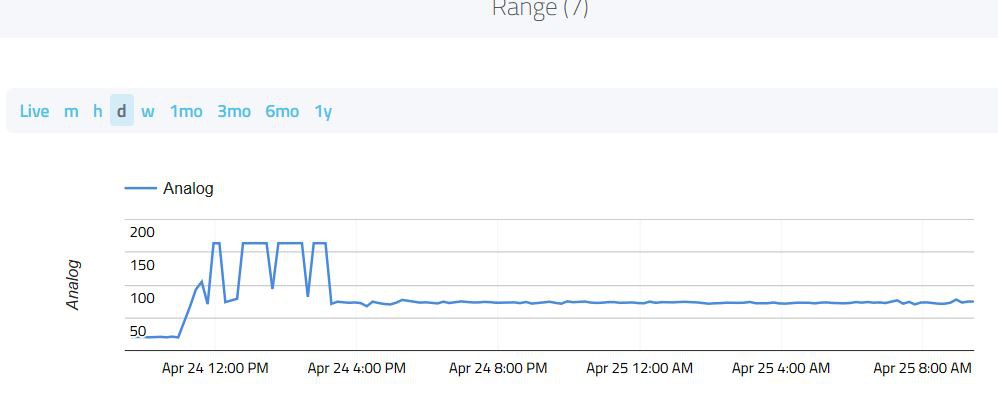 the Bin Level Monitor is still chugging away. Next update in a week.
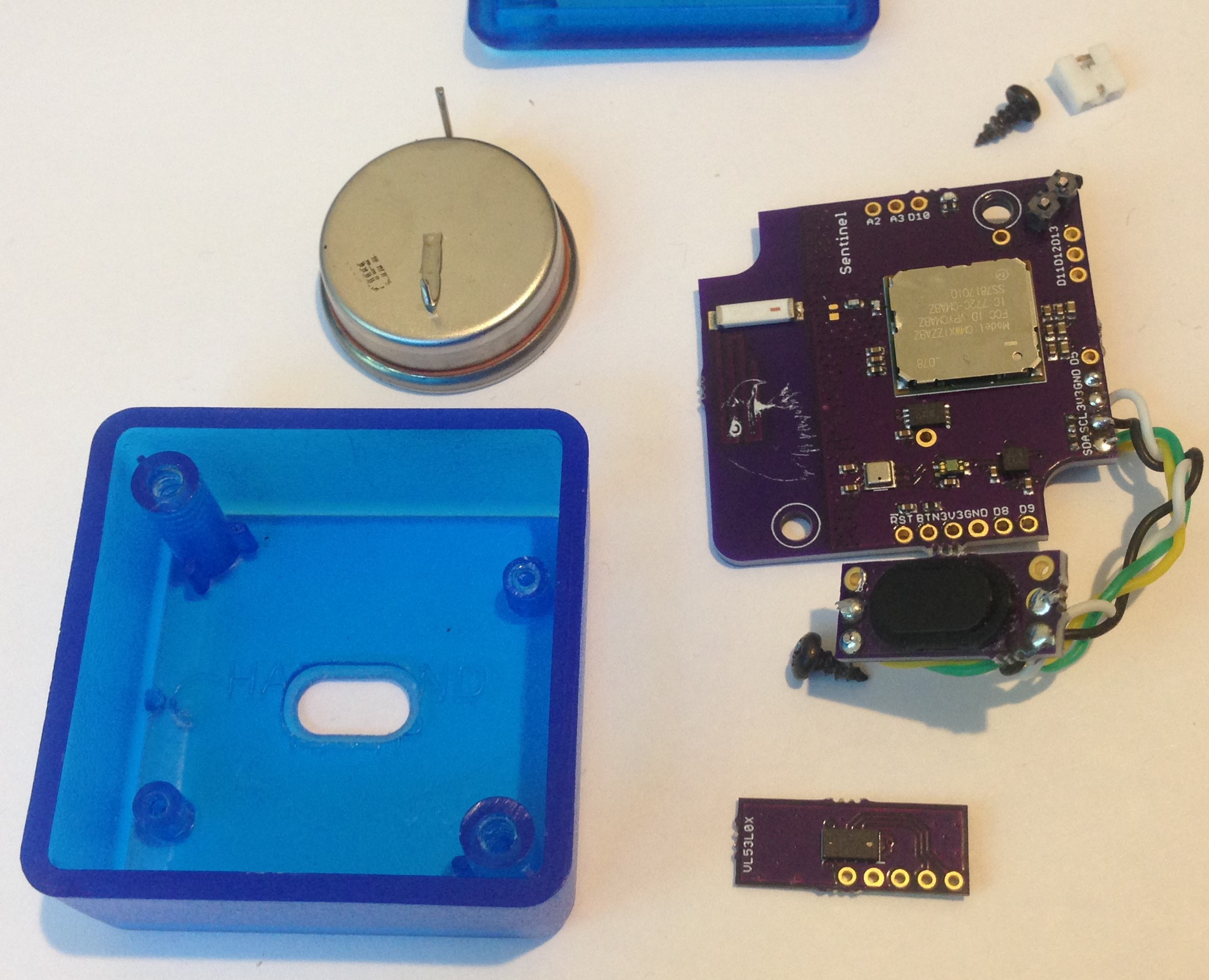 Machining such a complicated shape onto the side of the box proved impossible. But doing so on the box bottom was relatively easy (see above, thank you Greg Tomasch!). I also redesigned the VL53L0 carrier
 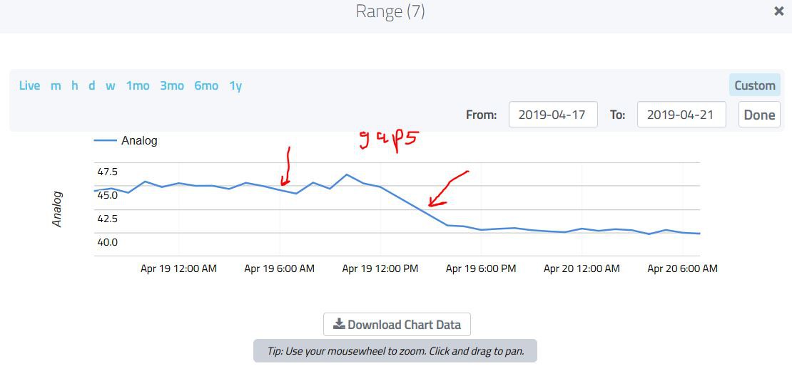 The nice thing about this is that the range is correct; the ranging sensor points straight down and sees whatever happens to be in the middle of the bin. I added some material to the bin a few times over the course of the two days and the bin level dropped from ~60 cm to ~46 cm and then to 42 cm, etc. So the main function appears to work well. I also recorded temperature, pressure, humidity, ambient light level and acceleration (really orientation of the bin lid). So all worked as it should have.
  I am holding the carrier board to the case with double-sided tape, the main board is screwed into the two case mounting holes as before and with the coin cell battery soldered to the main board the package is reasonably rugged and without jitter. A little pre-deployment bench testing to make sure all is working then out to the bin lid it goes. After a few weeks of real-world bin monitoring I will report results...