Alastair Hewitt
-
Problem Solved
03/19/2022 at 02:21 • 0 commentsAfter many weeks of detailed investigation... the "bug" with the ED command has been resolved!
![]()
I know there are not many fans of ED, but it appears to be so unloved that no one has noticed that a copy shipped with certain CP/M 2.2 distros is actually corrupted. Perhaps this is what you get for trusting garbage scraped off a 40-year old 8" floppy that was uploaded to the Internet. Arrrggg!!
There are still issues with Altair BASIC... but this was OCRed from a listing of dubious origin found at the back of an old manual. I'm willing to guess my 8080 virtual machine is not the culprit for this buggy mess either.
To be continued....
-
Three Years Later
02/21/2022 at 22:27 • 0 commentsIn keeping with the first and second year updates... here is year three! Normally it is a look ahead at the next phase of development, but things are pretty much complete at this point.
There is an outstanding issue causing a crash when running the ed command in CP/M and not much progress has been made in tracking that down yet. Enough of CP/M is working to run some of the existing CPU compatibility testers out there and these helped clear up the last remaining bugs. Unfortunately the ed problem persists, so there's something more to this than just the 8080 interpreter.
![]()
Sound Instructions
After no progress on the remaining bug the gears were switched to add some extended instructions to control the sound features of the platform (the plan is to also add some extended graphics instructions to plot points and draw lines natively).
There are 16 new extended instructions as follows:
Config Voice
Four 3-cycle instructions are used to configure each of the 4 voices with the following 8080 registers:
- A - Waveform
- 0 - sine
- 1 - sawtooth
- 2 - square
- 15 - noise
- BC - Attack (0-15) and Decay (0-15)
- DE - Sustain (0-15) and Release (0-15)
Set Note
Three 2-cycle instructions are used to set the note for voices 1-3 using the 8080 accumulator:
- A - MIDI Note Number (0-127. +128 for 60Hz VGA video timing)
This instruction will also update the specific version of the sawtooth and square waves to band limit the harmonics for the note frequency and prevent aliasing.
Since the frequency of voice 0 is fixed at the vertical video frequency, the instruction that would represent this note is used to control the level of voice 3. This is needed when using 60Hz video modes since the ADSR for the 3rd voice is only updated in the 75Hz VGA mode.
Gate On/Off
Eight 1-cycle instructions are used to gate each voice on and off. Gate on will start the attack/decay to the preset sustain level. Gate off will release the note back to zero.
PCM Playback
A new feature was also added to the audio thread to play back PCM samples. The sampled data is stored in bank zero and played back by specifying the start and stop page of the sample data. The sample size is capped at 32k to leave the other half of the memory for the display.
The simplest playback method is to write one byte per block to the audio register. This is a sample resolution of 8 bits at a rate of 9,593bps giving a bandwidth of around 4.8kHz. This is definitely not CD quality, but that rate is still fairly fast and 32k will only provide 3.4 seconds of playback.
A couple of other schemes can be used to increase the playback time: Halving the sample rate and companding. Half rate skips every other block to drop the sample rate to 4797bps with a somewhat underwater sounding 2.4kHz bandwidth.
The companding method (shown below) stores the log of the 8-bit sample as 3 bits plus a sign bit. This also halves the storage requirements as each sample takes up just one nibble. Combining these two schemes gives a maximum playback of 13.66 seconds for 32k of data.
log: rounded  :  range
...:..........:.........
-8 : 10000000 : -80..-41
-7 : 11000000 : -40..-21
-6 : 11100000 : -20..-11
-5 : 11110000 : -10..-09
-4 : 11111000 : -08..-05
-3 : 11111100 : -04..-03
-2 : 11111110 : -02
-1 : 11111111 : -01
 0 : 00000000 :  00
 1 : 00000001 :  01
 2 : 00000011 :  02..03
 3 : 00000111 :  04..07
 4 : 00001111 :  08..0F
 5 : 00011111 :  10..1F
 6 : 00111111 :  20..3F
 7 : 01111111 :  40..7F
The PCM playback is handled as a separate audio mode and the various playback schemes are added as an additional four audio modes. The complete list of modes is as follows:
- 0 - mute
- 1 - 1+1 voices
- 2 - 2+1 voices
- 3 - 3+1 voices
- 4 - 8-bit PCM @ 9.6kbps - 9.37kB/s - 3.42s playback - 27ms per sample
- 5 - 4-bit PCM @ 9.6kbps - 4.68kB/s - 6.83s playback - 53ms per sample
- 6 - 8-bit PCM @ 4.8kbps - 4.68kB/s - 6.83s playback - 53ms per sample
- 7 - 4-bit PCM @ 4.8kbps - 2.34kB/s - 13.66s playback - 107ms per sample
- A - Waveform
-
Kits are coming...
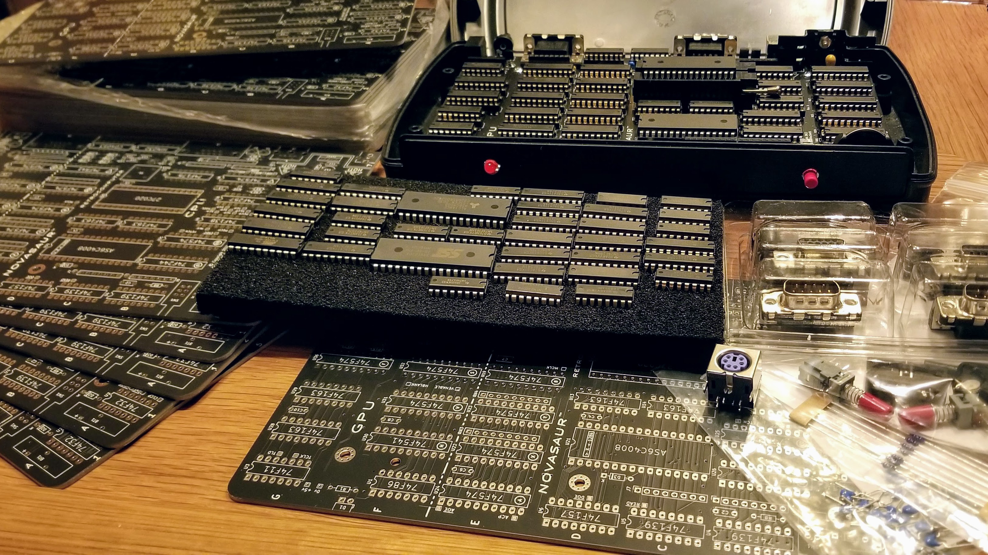
01/10/2022 at 05:10 • 4 commentsThe first batch of Rev A boards have arrived. This may sounds like the first revision, but the revisions are being counted in hex, so "A" is actually the 10th! It's almost identical to Rev 9. except for a larger regulator and some ESD protection on the VGA circuit. These were the final updates before the board was ready for public release in a kit.
![]()
A prototype of the new board was tested this weekend and passed all the stress tests. There are parts on hand to build two more kits, but like many projects there are growing issues with sourcing more components.
One example is the ROM. The only available part that meets the timing specifications is the AT27C020-55PU. These have more than doubled in price since the start of the project and are now out of stock with a 65 week lead time. Luckily is appears the NOR flash used during development works fine at 55ns even though it is rated at 70ns. The plan is to use this for the kit.
Some of the other parts were at risk, so initial orders have been placed for these. The rest of the parts should be available when needed for a total production of 100 kits during 2022. The plan is to release an initial batch of 20 beta kits in Q2. These will likely be just the basic board-only kit to keep the cost down and come with limited documentation. The full kit should be available in the second half of the year with enclosure and full documentation.
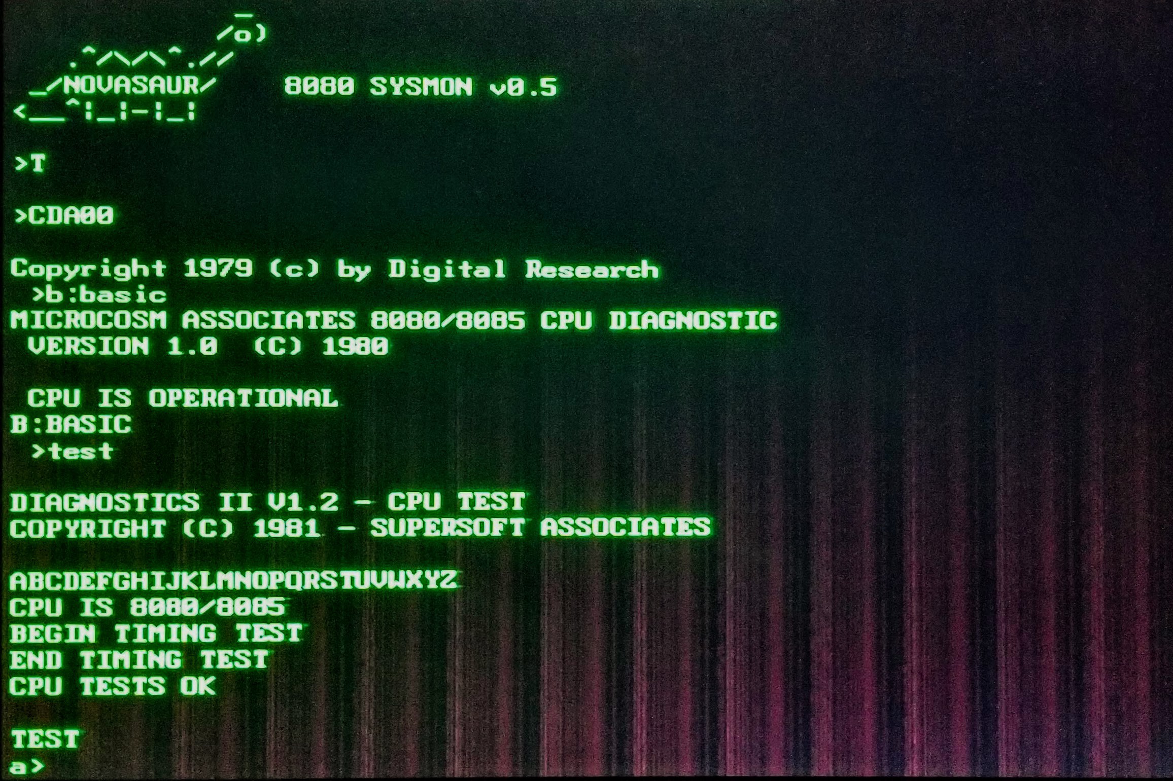
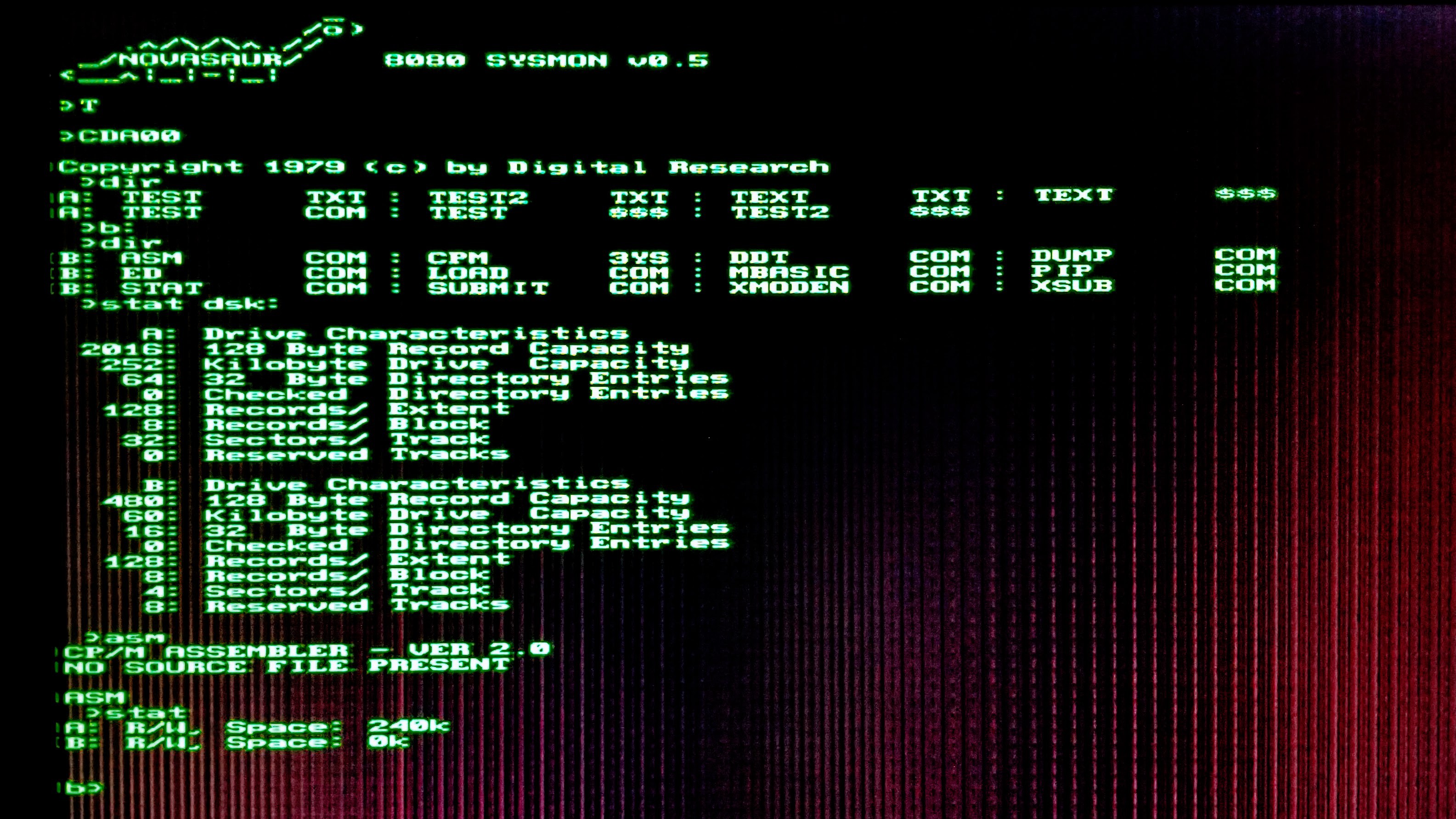
Software debug is progressing well. The B: drive has been set up and the CP/M utilities are being tested. Most things are working (like STAT shown below) but ED is crashing for some reason. Software development should be wrapped up within the next few weeks for the beta kit release.
![]()
-
CP/M is Running!
12/30/2021 at 20:14 • 0 commentsAn unofficial goal of 2021 was to get CP/M 2.2 running on the Novasaur. I'm close enough to officially claim that goal had been achieved... with less than 48 hours to go!
![]()
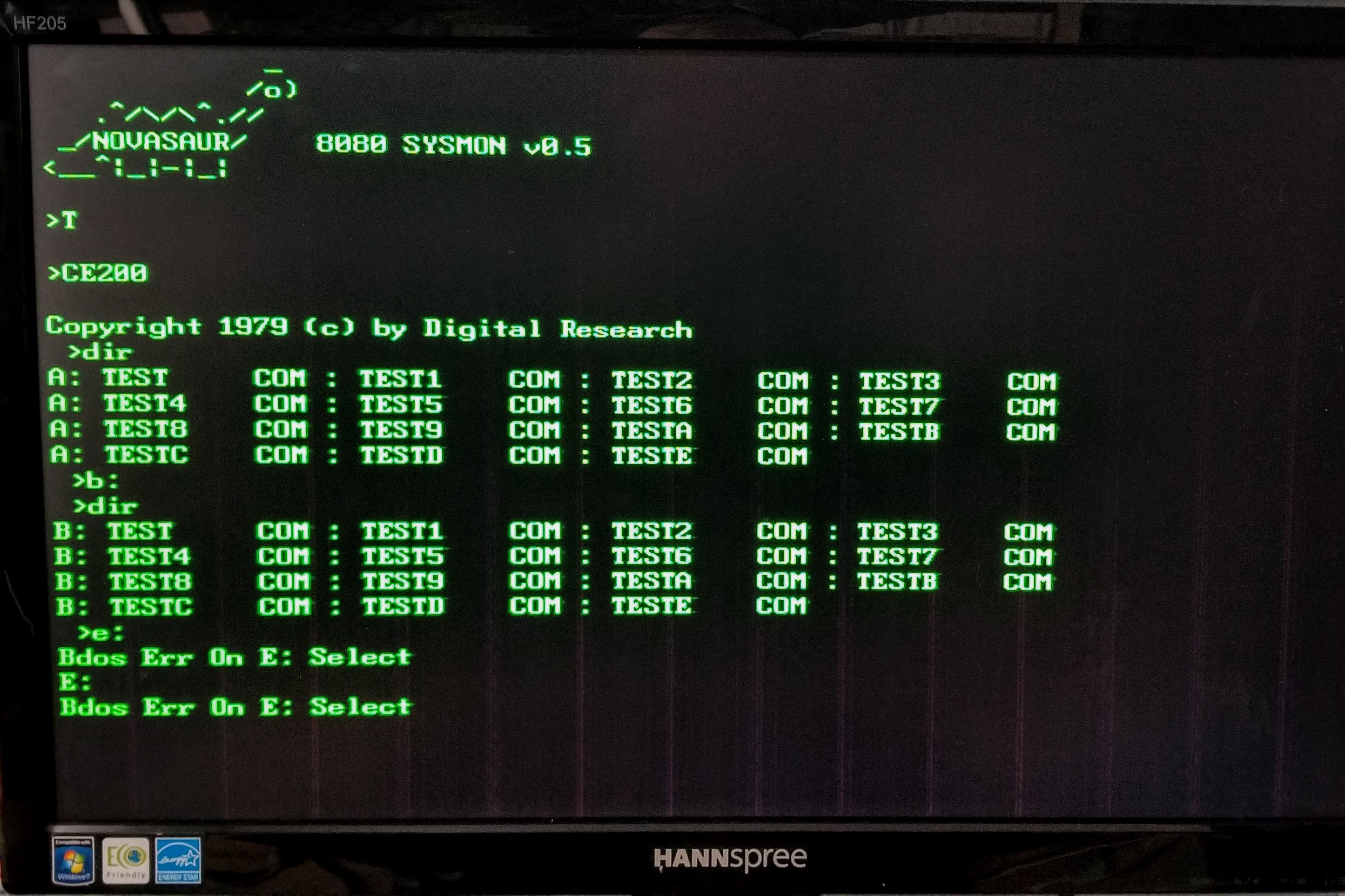
This isn't the final configuration though; CP/M is running alongside the kernel on CPU 1 and is started by calling the CCP at 0xE200. This is temporary since the goal is to have CP/M run in its own CPU instance. In fact, the plan is to have two instances of CP/M running: One with console IO and the other with serial IO.
For now the initial BIOS development is being done alongside the kernel and system monitor for debugging. That debugging took the vast majority of the time, but ironically not as part of the BIOS development.
There were still a few bugs in the 8080 virtual machine. Not every instruction is being used by the monitor so there were still a few that were not fully tested. These caused some strange behavior in CP/M and proved very challenging to identify. The fixes were usually simple, but figuring out what was broken involved extensive reverse-engineering of the CP/M BDOS and CCP.
There are a couple of minor issues remaining: Saving large files can result in an error and if an invalid disk is selected the system gets stuck with that invalid disk selected (as can be seen above). These should be fixable with some additional error handling in the BIOS though.
Only the A: drive is working right now, so the next stage of development is to add the B: drive. This is a read-only drive mapped to the 64k cold-storage area of the ROM. The plan is to store the following CP/M tools and utilities there:
- CPM.SYS (6k) - CCP/BDOS/BIOS (loaded by boot loader).
- STAT (6k) - Lists the number of bytes of storage.
- ASM (8k) - Loads the CP/M assembler and assembles.
- DDT (5k) - Loads the CP/M debugger into TPA and starts execution.
- PIP (8k) - Loads the Peripheral Interchange Program.
- LOAD (2k) - Loads command from Intel HEX machine code format file.
- DUMP (1k) - Dumps the contents of a file in hex.
- SUBMIT (2k) - Submits a file of commands for batch processing.
- XSUB (1k) - Extension to submit command.
- ED (7k) - Loads and executes the CP/M text editor program.
- MBASIC (8k) - Microsoft BASIC-80 for CP/M
- XMODEM (5k) - Used for File transfer over serial.
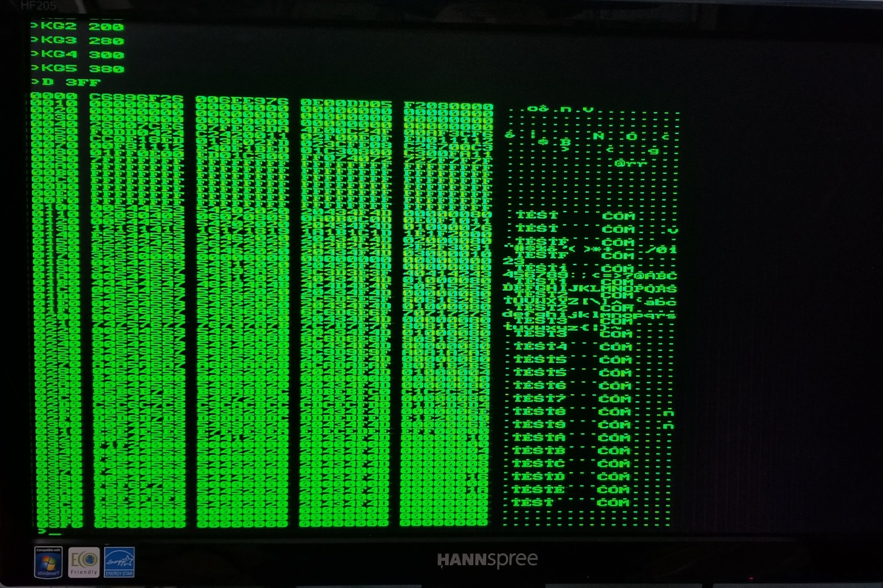
The example above shows the B: drive being selected, but this currently maps to the A: drive with the same directory. This directory is shown below by using Kernel GET commands to copy the first six records from the A: drive to the memory locations 0x0100-0x03FF.
![]()
This example shows several test files created using the CCP's SAVE command. The speed to save data was measured at around 6k bytes per second, so the largest file would take up to 10 seconds to save to the disk. Not that fast by today's standards, but perfectly reasonable for the late 70's!
-
A: Drive
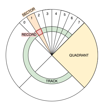
11/18/2021 at 04:06 • 0 commentsThe A: drive has 63 tracks across 4 quadrants. Each quadrant has 8 sectors making up a total of 32 sectors per track. The record size is 128 bytes for a total of 252k bytes (63*32*128). The first 2k is used for the disk directory leaving 250k available for storage.
![]()
The decision was made a while ago to use a RAM disk and a detailed design was discussed earlier this year. It's taken about 6 months to develop the code and get it working (amongst other things). The net result is the initial version of the micro kernel weighing in at a whopping 160 bytes of 8080 machine code!
:20F000003A80E8B7C0ED06AF3CE607CA00F03281E8DD09B7C208F079FE04D205F0FE01DA45
:20F0200005F0CA2BF02190F0F240F02141003A81E8CD4CF07EB7CA05F0360023E52198F04A
:20F04000D5875F1600195E2356EBD1E9C6E8677887876FC97B0F0F0FE603F604C9CD54F012
:20F06000DD08B7CA05F0CD4CF036023A81E82377C305F0E16E3A81E8677DED0BDD07C30585
:20F08000F03A81E867CD54F06FED0BDD08C305F005F005F05DF081F005F005F073F005F077
This initial kernel supports two operations: GET to read a record from the drive, and PUT to write a record to the drive. The record is specified using the DE register to represent the track (D register) and sector (E register). The most significant 2 bits of the sector are used by the kernel to determine a quadrant. Each quadrant is assigned to one of 4 virtual CPUs, each with its own 64k of RAM.
Each of the quadrant CPUs run a program to respond to commands from the kernel and read/write records from the memory it manages. The following code maps the track/sector in DE to the memory location:
    MOV     A,D     ;A=00TTTTTT
    CPI     63
    JNC     WAIT    ;SKIP TRACKS>62
    MOV     A,E     ;A=000QQSSS - 4 QUADS OF 8 SECTORS
    RRC             ;A=S000QQSS
    RRC             ;A=SS000QQS
    RRC             ;A=SSS000QQ
    ANI     0E0H    ;A=SSS00000 - CLEAR QUAD
    MOV     E,A
    XCHG            ;HL=00TTTTTTSSS00000
    DAD     H       ;HL=0TTTTTTSSS000000
    DAD     H       ;HL=TTTTTTSSS0000000
    INR     H       ;HL+0000000100000000
    PUSH    H       ;SAVE HL
The current software still boots to the monitor program, but the monitor can now set a break point and call the kernel code to allow records to be read and written to the A: drive. The next step is to add some kernel commands for console input and output and plumb everything through with a CP/M BIOS.
The assembler code for the operating system can be found here: https://github.com/ajhewitt/novasaur/tree/master/src/os
-
Show Time
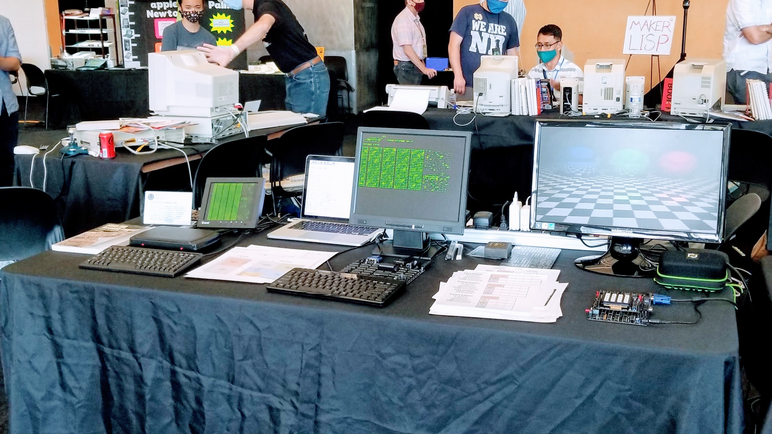
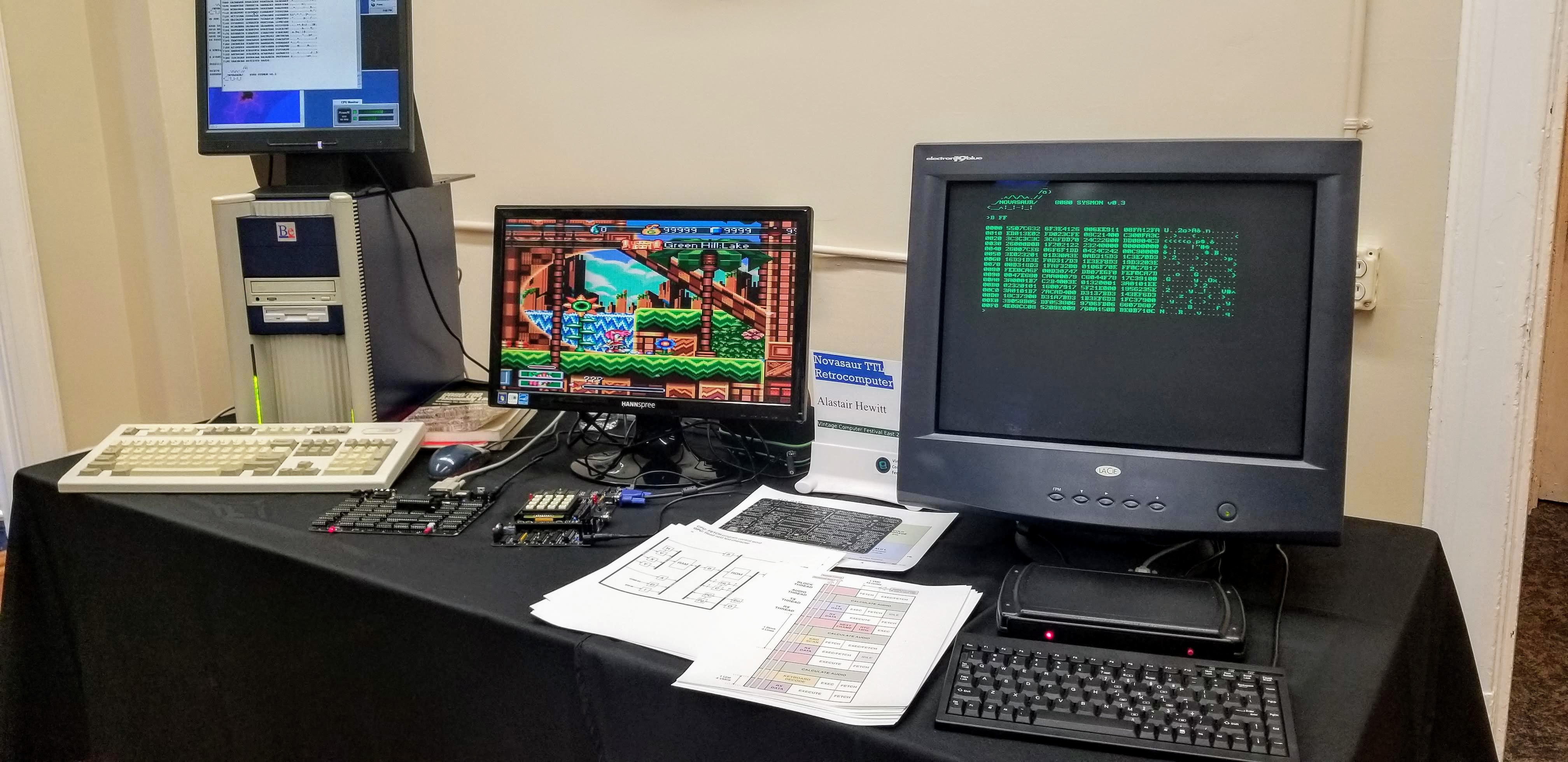
08/07/2021 at 17:18 • 0 commentsThe Novasaur is hitting the road this summer/fall. The first trip was to VCF West at the Computer History Museum in Mountain View, CA.
![]()
Next up is VCF East at the InfoAge Science and History Museum in Wall, NJ.
![]()
Both rev. 8 and 9 boards are on display with demos of the text mode/8080 machine monitor, polyphonic/ADSR sound generator, and expansion card. A limited number of Rev. 9 PCBs were given out at VCF West and it looks like these will be very close to the final Rev. A release.
-
Expansion Board (again)
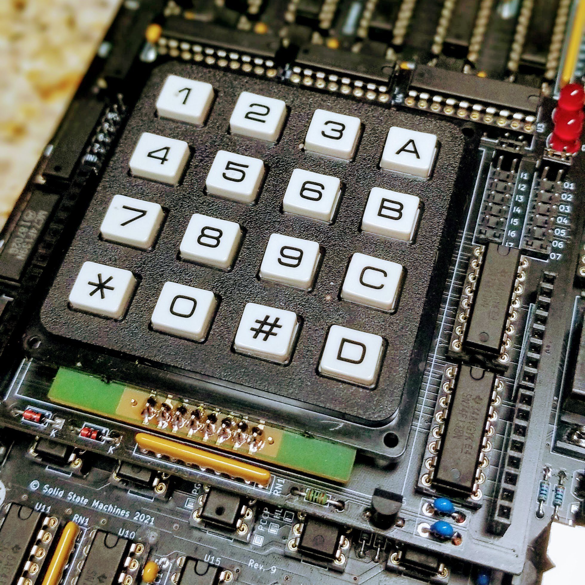
06/27/2021 at 03:58 • 0 commentsThis is a follow up to an 18 month old log describing an expansion board. An initial version was built way back alongside the Rev. 2 board to test the electrical interface. The plan was to use the numeric number pad as a stop-gap keyboard for testing until the PS/2 keyboard scan code was completed. In the end the project pressed forward to build out the PS/2 interface and the expansion board was forgotten.
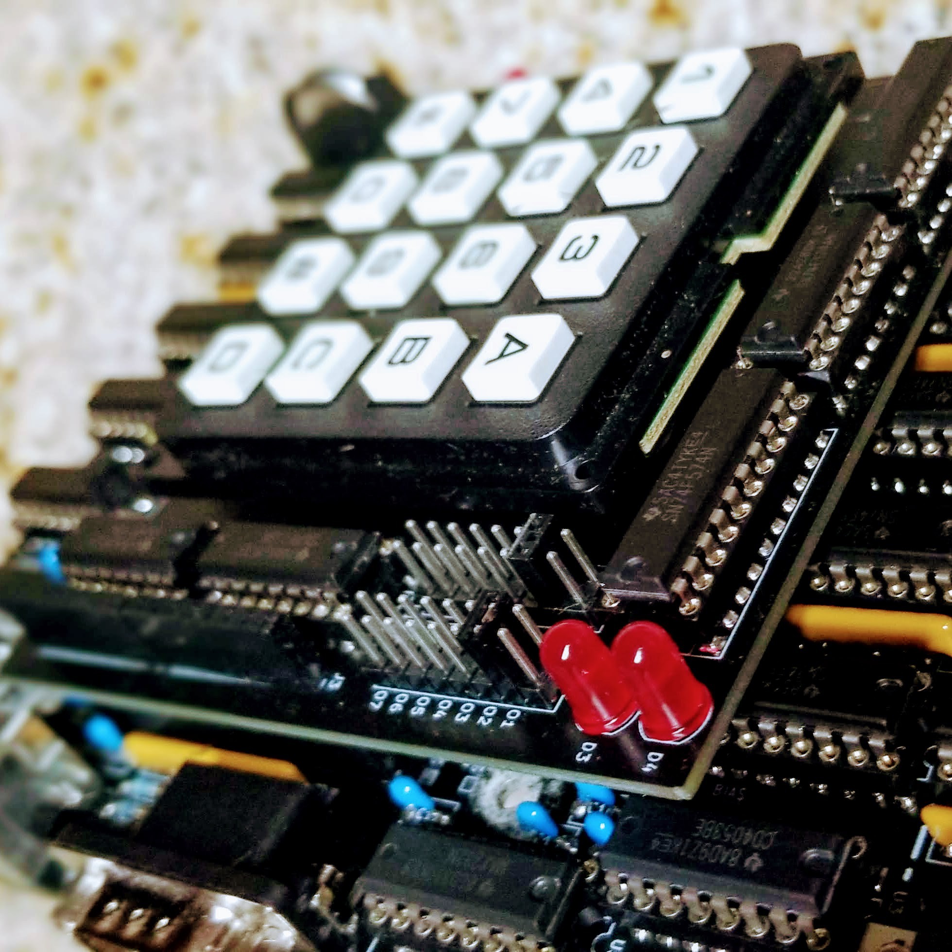
Fast forward to Rev. 9 and a new version of the board was built with some minor adjustments. The main regulator is maxed out, so the 6V supply is now passed to the expansion board and a local LDO regulator is used to power the board.
![]()
The original design also used a pair of 16-pin headers to connect the board. A more cost effective option is to use two pairs of 8-pin headers. These headers are standard on the Arduino and in plentiful supply.
![]()
This expansion board is now easy to access thanks to the I and O commands in the 8080 monitor. These commands read and write to the input/output ports, where ports 1-7 represent the seven available expansion registers.
This test board uses register 7 to scan the keyboard matrix and provide a couple of badly needed blinkenlights. A pair of jumpers are used to map a single 8-bit flip flop to any of the other expansion registers. There is also a header to break out the 8085 interrupt lines (still needs testing).
-
Rev. 9
06/23/2021 at 01:51 • 0 commentsRev. 8 was supposed to be the final "pre-release" board, but a few minor updates turned into a fairly major refactor of the power distribution. The result has been impressive...
![]()
![]()
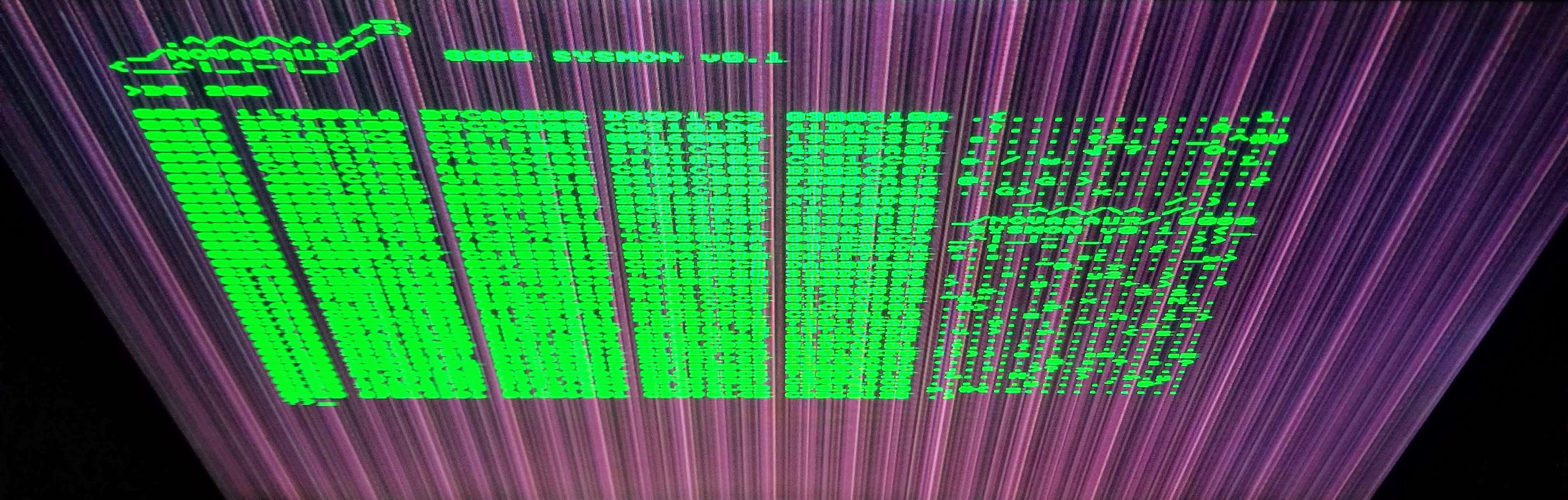
Note: these photos greatly exaggerate the background power supply ground noise. This isn't exactly what it looks like under normal viewing, but the it is very noticeable on this monitor when viewed from above (the photos also have a filter to increase the contrast).
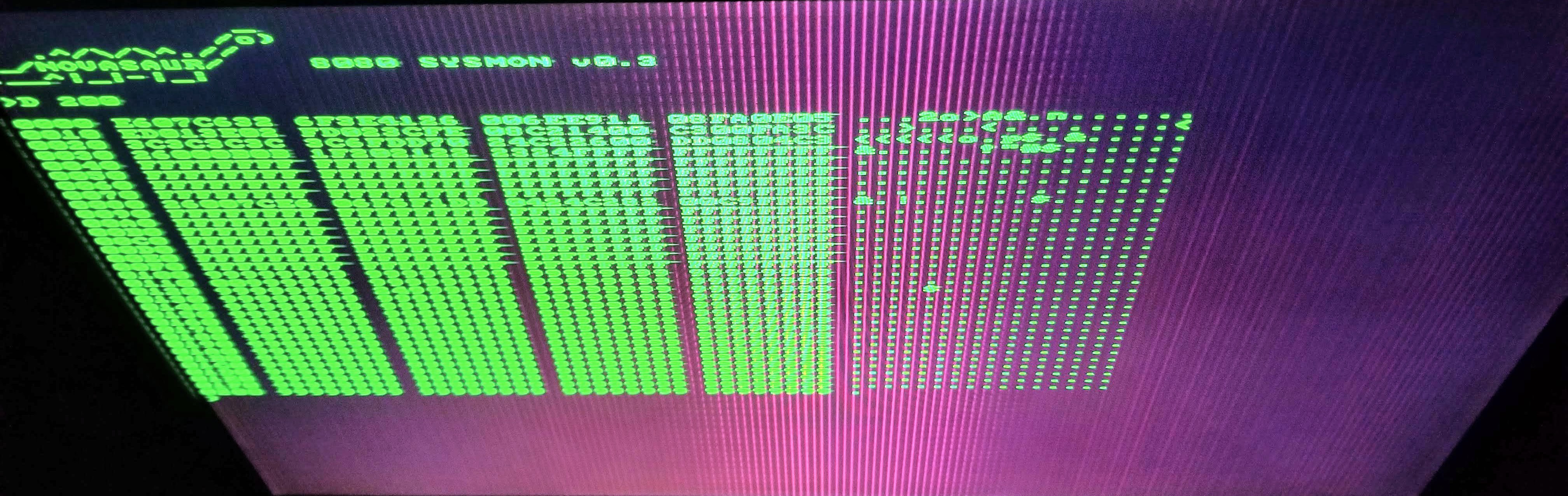
The first photo is from the Rev. 8 board and the periodic noise from the ground plane is very noticeable (even this was an improvement from the Rev. 7 and earlier boards). The second photo is the Rev. 9 and the periodic noise is almost gone.
There is still a high frequency component modulated with a period matching the horizontal frequency. It rises to a peak in the center of the screen and looks like a CRT phosphor burn... an unexpected but very cool retro effect!
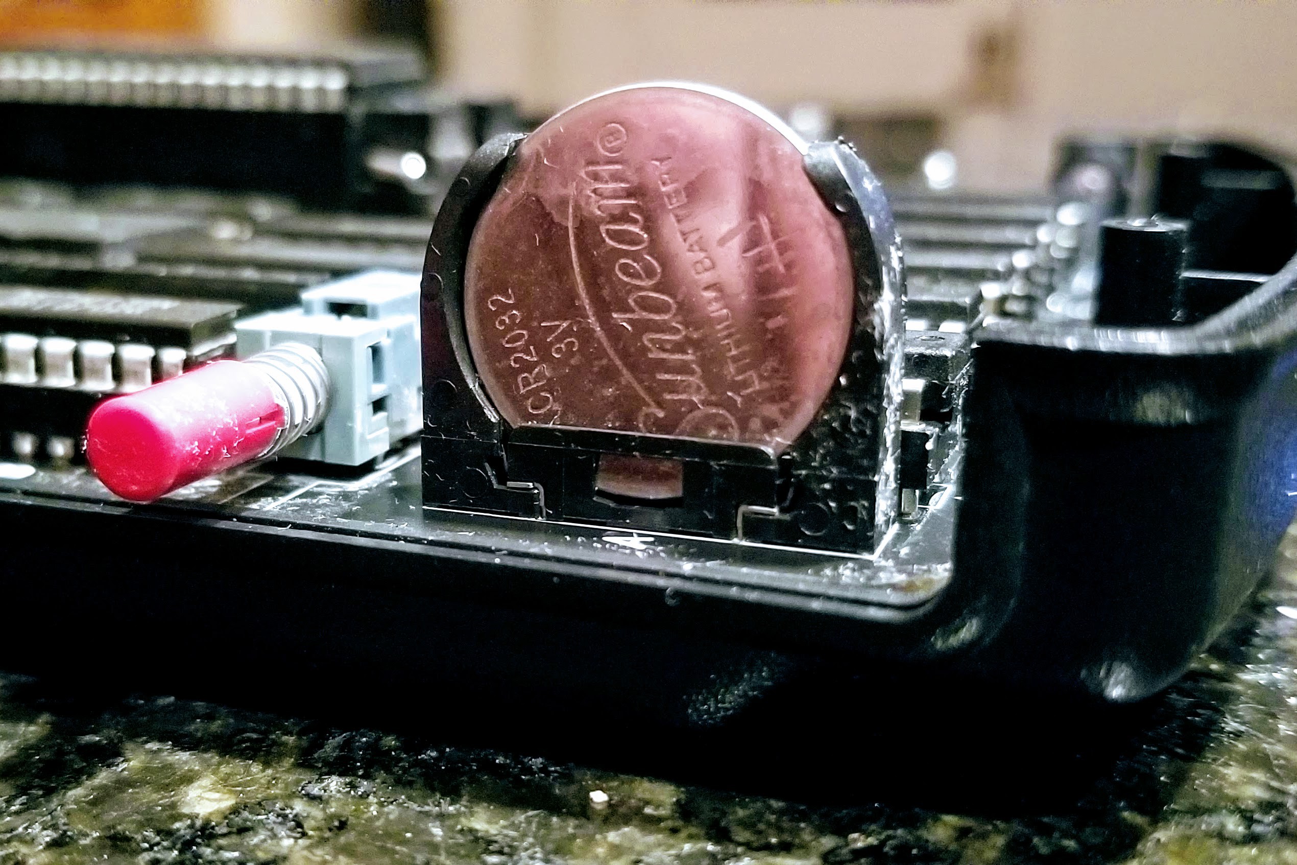
There were three component changes - the volume control and reset button have been added back. These aren't really necessary, but it's more fun to have extra knobs and buttons to play with. The other change was ditching the super caps and switching to a battery. The super caps could backup the memory for almost a month, but a CR2032 can last up to 5 years.
![]()
-
Quad Core Demo
05/30/2021 at 02:59 • 0 commentsThe ability to do preemptive multitasking was discussed in a previous log. The code was checked in almost 6 months ago, but it's taken until this week to finally debug and test. The following demo image shows the kernel executing the memory dump command and three other CPU instances each updating the colors in a single column on the screen.
![]()
It took the development of several additional features to set up the context switching and initialize the various CPU instances (note, each CPU has its own RAM bank and there's no way one CPU to access another's RAM bank).
A Boot Loader is used to initiate the CPU instances and each CPU context will copy a different section of code to initiate that CPU and memory bank. CPU 1 is the kernel and the only context that can issue a BOOT command. On start up the kernel issues this command to each of the other CPUs and then updates the context switching table to set the sequence and priority for the other CPUs. Each CPU will then boot as the context is switched to that CPU instance. The boot loader then copies the code related to that CPU and starts execution.
The example above gave each CPU an equal weighting. This results in about 15 KIPs to each CPU and is the reason why the memory dump is running fairly slow.
-
RTC and KIPs
05/18/2021 at 04:52 • 0 commentsOne feature of the Hardware Abstraction Layer that hasn't been discussed yet is the Real-Time Clock. This isn't some super low-power CMOS chip keeping track of time using a button cell, but an extension of the video timing to keep track of seconds, minutes, hours, and days. It runs as part of the block sync thread and needs all 10 watts to keep track of time!
![]()
The frame rate is either 60 or 75 Hz and this is divided by either 4 or 5 to generate a 15 Hz reference. This is used to trigger the PS/2 keyboard scan and increment the counter TIME0. This counter starts at -90 and counts up to zero, overflowing every 6 seconds. This overflow increments the TIME1 counter, which in turn counts up from -120 to zero and overflows every 12 minutes. TIME2 is then incremented and also counts for -120 to zero to overflow every 24 hours. The final TIME3 counter is then used to track the number of the days.
This may seem like an odd design, but it's based on efficient 7-bit arithmetic to keep the code compact in terms of both space and time. There are custom instructions to read these registers and return the time in the more conventional second, minute, and hour format. There is also a provision in this design to adjust TIME0 by one count every 16 counts of TIME1. This adjustment corrects the RTC to within several PPM, or losing less than 5 seconds per week.
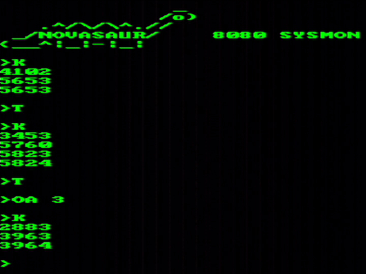
One of the first uses of the RTC is the K command in the system monitor and is used to measure the speed of the byte-code interpreter. The image above shows the command running and returning a value every 6 seconds (after the first incomplete run). The values shown are the BCD counts for a 60-instruction loop of 8080 machine code. Inserting a decimal point in the middle of this 4-digit number represents the interpreter speed in kilo-instructions per second (KIPs).
The monitor starts up with serial support turned on, so the Rx and Tx threads are running and the speed comes in around 56.5 KIPs. The T command toggles the serial mode off and this increases the speed to the maximum 58.25 KIPs, or around 1/5th of the original 2 MHz 8080 rated 290 KIPs. The final example shows everything turned on: The serial mode is toggled back on and the audio thread is started with all three melodic voices enabled. This drops the speed to 39.6 KIPs, or between 1/7th and 1/8th the speed of the original 8080.
Novasaur CP/M TTL Retrocomputer
Retrocomputer built from TTL logic running CP/M with no CPU or ALU