A handheld interface from the future or past.
To make the experience fit your profile, pick a username and tell us what interests you.
We found and based on your interests.
Alright!
The DSKorder is finally back to its former self. The replacement screen and battery charge circuit are implemented, and it's pretty much as it was before. Beautiful little thing <3
So, what better way, I thought, to celebrate this little achievement than by trying something I had been wanting to play with for a while already:
A small "DIY-TTS" on the ESP32!
I knew that a proper TTS would be a bit tough to implement, sure. But simply pre-generating a list of just the words and phrases that I need, packaging those into a "small" header-file, and adding some fancy code to play that back ... That couldn't be so hard, right?
Turns out I was quite correct, and after a good afternoon and evening of happily crunching away on some Ruby code to generate headers for audio data, I was finally left with this:
((Sorry for the vertical video >.>))
The audio is a bit quiet, but that's because the speaker of the DSKorder is TINY, and not very good for low frequencies. Sadly, limiting the audio sample-rate to a whopping 5510Hz at eight bits does leave you with only low frequencies to mess with. In my tests I turned the samplerate up to about 8k without exceeding about 300kB of memory needed, so it's definitely possible to get a better quality. Heck, add a SD card with the sound files and you could smoothly ride along at the full 44100Hz!
The system can only say words that have been pre-generated, but it DOES handle numbers fully, so it's still quite useable!
Overall, this was a very fun little thing for me to work on, and I bet it'll be useful in some situations. Maybe for a tiny screen-less multimeter with earplugs?
Gha ...
I've already written this as a comment on Jan's project about his blown-up LDO, about how I've been struggling with a similar problem, but I wanted to post a project log update as well.
During recent, normal operation, I had the pleasure of hearing a sudden "pop" somewhere inside the casing. Now, as far as I know, that's not part of what these chips are supposed to do, and when you smell magic smoke, something is definitely broken.
In order to prevent even more from breaking, I had to take the casing apart as quickly as possible, and cut the wire of the LiPo, as parts of the charge circuit were connected directly to the battery, with no switch in between.
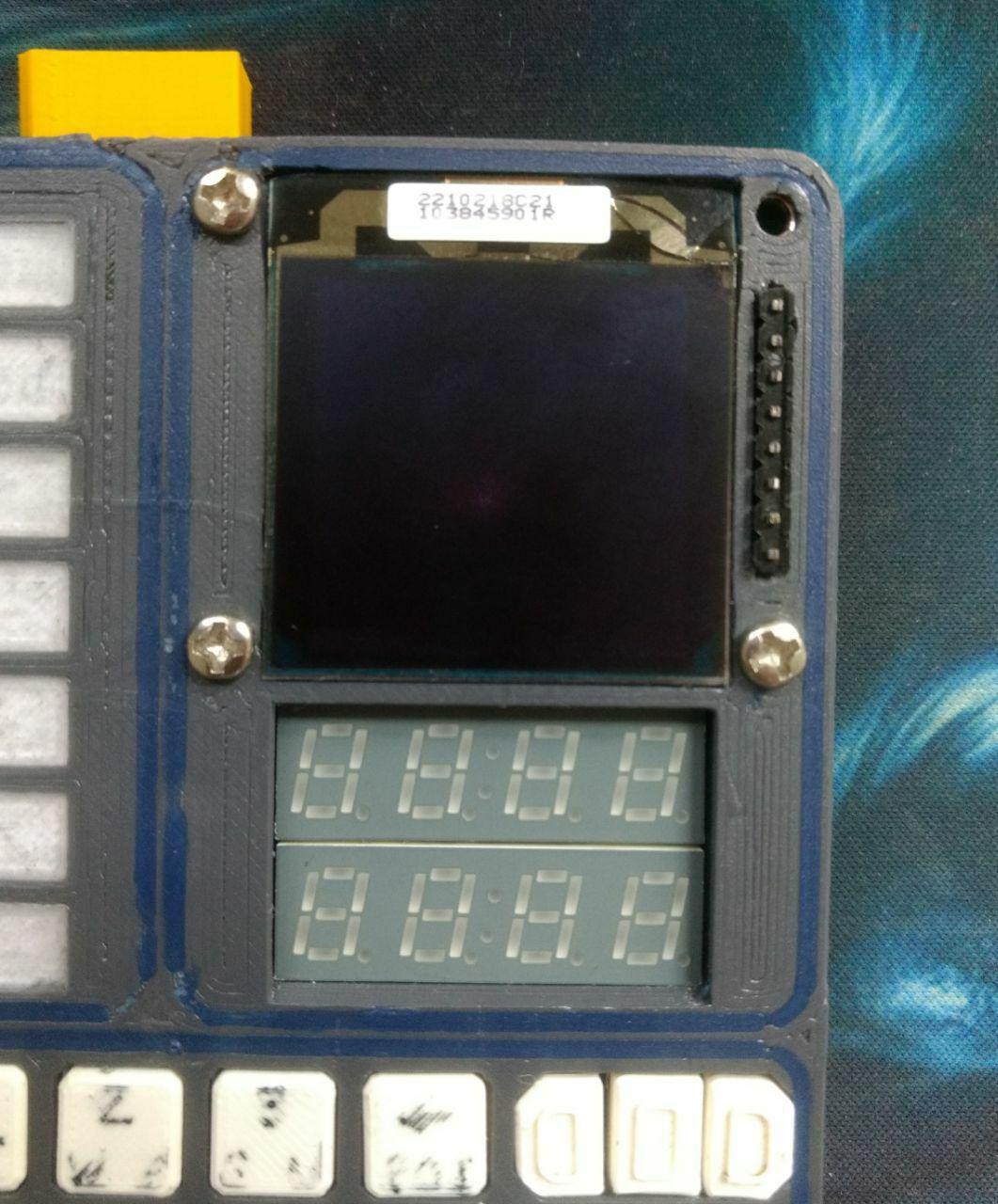
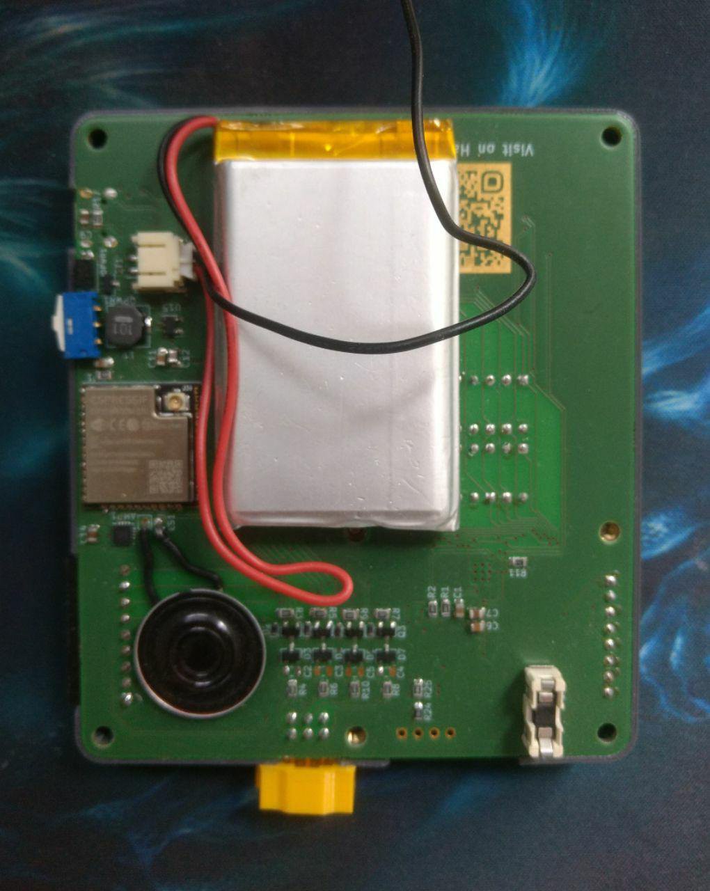
During "post-op", I managed to get a closer look at what had happened. There are no visual marks or popped ICs, but I am very sure the charge IC, a MCP73832T, is at fault, because the "charging" LED had been glowing with no cable plugged in. In fact, this is the same chip that failed on my Lasertag project!
Although I might not have added aaaaalll the smoothing capacitors, there was a 10uF on the input and output side, so I am definitely going to look for a beefier IC.
As for the DSKorder itself, I was able to desolder the broken IC and power the circuit via USB. Nothing else was damaged, and even the USB-To-UART chip, which is powered from the same line as the Charge IC, responded just fine.
I'll replace the broken IC with an external 500mA charge board, so ... All's well!
Just need a better charge IC for next time.
Man, I really am a bit lazy with this documentation, am I not?
Well, considering that this is mostly just a comfy project for myself, I suppose it's alright ^^'
Anyhow!
Over the past few weeks, the DSKorder has received continuous but relaxed polishing, as one does. Functionality is starting to improve, and we're slowly munching through some few bugs in the software.
One small note: The AS1115 LED and button matrix driver is starting to become a pain in the butt.
It does what it's supposed to, however, it decided to not react to the "Self-Addressing" command any more. This means it now occupies the I2C address of 0 - not the best, but since so far nothing else is using General Call, it'll survive.
I'm still looking for replacements.
In fact, let's give you a closer look to that last part:
Yes, yes I know. The usefulness of a MIDI-File on such a little handheld device is ... Marginal. However, this was a great test for ... Err ... Sequenced ... Somethings ...
Alright fine I just wanted it to play funky music. But it works great, give or take the audio artefacts from the tiny-ass speaker it has, and in theory we should be able to use this for our Lasertag project as well - by allowing us to add very long runtime background music with minimal memory consumption! (Seriously, these MIDI's are TINY)
Anyhow, we'll be continuing our work on the DSKorder as need arises. Next up will be, for example, establishing various communication protocols like UART, I2C or SPI, as well as adding a voltage level monitor on the external pins to be able to read out battery voltage and current consumption!
Well, been a while since the last log entry, hasn't it?
Don't worry, you haven't missed much ... Apart from getting the WiFi to work, finalizing how programs are run, adding a first set of those, and working on implementing a first sensor attachment - and what could be better than the very powerful (but slightly expensive) BME680!
I gotta say, it was a beast to get working, as the calibration methods used by the manufacturer are ... Extensive (do we really need a quadratically temperature-corrected humidity display? Maybe, maybe not), but my god the sensor data it provides is really smooth.
I've also gotten around to adding a proper casing to the sensor and, what's more important, it gets auto-detected when you plug it in!
The best part is the WS2812 LED in the BME's casing, which gives a visual air quality reading as a colorfade from Cyan (freaking great air) to Green (your standard, everyday oxygen) to orange and red (a literal brick wall to walk into).
If the DSKorder is connected to a MQTT server it also publishes the information onto the network, making it quite easy to use the DSKorder for remote air quality monitoring!
Oh boy ... I kinda didn't keep this thing updated, did I?
Is it OK if I just say I was busy? >.>
Truth be told, I was just having too much fun and was moving quite fast with this lovely piece of hardware, so keeping it up on Hackaday kinda fell out of my mind.
Let me make it up to you with a picture of how it looks so far:
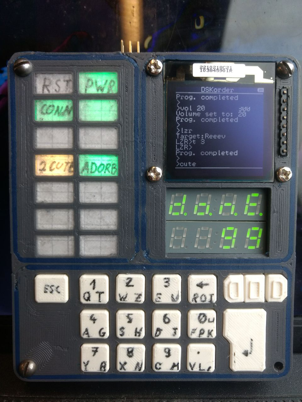
Yeah, that's right!
It's pretty much ready for action, and doing damn fine, too!
Let me walk you around the whole system for a moment:
The top left section is a status indicator panel. Text can be written on a slip of paper that is fairly easy to swap out, making it flexible. Right now it's displaying it's own battery status (fades to red), WiFi connection, Program status, as well as program-specific parameters.
The whole thing is realized using 14 WS2812b LEDs, and it's actually animated with various blinking effects!
Added bonus: All animation cycles are synchronized, including the OLED screen's "typing" indicator. Just because ;)
On the top right we have the OLED screen. It's main purpose is to be a console, outputting information, letting the user type etc.
It also features a status-bar with system info on the top, and any running program can draw graphics over that as it pleases. I'm actually using my own library for the OLED screen, optimized for speedy updates over the I2C port :>
Right below the screen we have the two 7-segment segments. To be quite honest they can only effectively display numbers, but they do it in style!
I just don't think this device would have quite the same charm without those gorgeous numbers on it!
For added functionality they can also display small animations for "LOAD", "DONE", "RUN" and "ERR" - always pleasant :>
On the bottom of the DSKorder we have the keyboard. It's driven by the same chip as the seven segments, actually, and while it works well I'm kinda searching for alternatives. For example, the chip's default address is 0. Yeah - The I2C Global call.
Anyhow, it works like any 'ol keyboard. You got your Enter and Escape buttons, and then your keys. The three buttons in the top right are "modifiers", equivalent to Ctrl, Shift and Alt (but not quite <.<)
We also have a few hardware connections!
On the top left we have the general purpose expansion slot, with access to power and I2C, as well as the four General Purpose I/O channels. Useful for attaching extra sensors and such.
And on the very front we have the four protected I/O channels! I've tested them for up to 24V input and the ESP will only see 3V - and even if the ESP pulls the line to low, a resistor limits the whole thing to ~70mA. Not nice, but surviveable. They also have a protection diode so ESD spikes can't get it. Yeah, I went a bit overkill with these.
In addition to the four I/O lines we also have three analog inputs - one scaled to work well up to ~5V, one for ~24V and one connected to a current sense amplifier, which means it's easy to monitor Vcc, Battery voltage and current draw!
The DSKorder also has a bit of internal periphery, consisting of a LSM6DS3 accelerometer, should anyone want to use it as a sort of remote control with tilt functionality, has a speaker with which it plays gorgeous StarTrek Tricorder noises (video on that comin' in soon :3), and a 2000mAh battery + charge circuit, if you ever need to run a marathon nerd-day and can't bother charging this thing!
Create an account to leave a comment. Already have an account? Log In.
Become a member to follow this project and never miss any updates
 deʃhipu
 Stephen Holdaway
 svofski
 Aaron
Aaron
That is so way up there on my cool-meter :-D