Small Word Clock
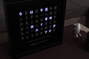
I've been in a clock making sort of mood recently and I've seen tons of word clocks so I thought it was time to give it a try
I've been in a clock making sort of mood recently and I've seen tons of word clocks so I thought it was time to give it a try
To make the experience fit your profile, pick a username and tell us what interests you.
We found and based on your interests.
Wordclock_lightbox.SLDPRTLightbox Solidworks filesldprt - 951.50 kB - 05/15/2020 at 19:36 |
|
|
Wordclock_lightbox.STL3D Printable Lightbox STLStandard Tesselated Geometry - 171.18 kB - 05/15/2020 at 19:36 |
|
|
word clock.hexFirmware with configuration words included for programming standalone (Fixed typo "Fourty" to "Forty")- 46.50 kB - 09/23/2019 at 13:42 |
|
|
word clock v1.1.zipMicrochip MPLab Project Files (Including precompiled Hex, Fixed typo "Fourty" to "Forty")application/x-zip-compressed - 28.04 kB - 09/23/2019 at 13:41 |
|
|
wordclock_2019-09-23.zipGerber Files for PCB Manufacture (Fixed typo "Fourty" to "Forty")x-zip-compressed - 495.64 kB - 09/23/2019 at 13:11 |
|
Huge thanks to Makerfabs for helping me turn my word clock into a product. Check out the sales link here: https://www.makerfabs.com/small-word-clock-kit.html
Just a quick but huge update. I'm currently working with a company which manufactures electronics kits to turn this project into a viable product. We are still working kinks out of the manufacturing steps, but expect to have my word clock publicly available for purchase as either diy or fully assembled (yet to be determined along with pricing). So those of you who want to get your hands on this word clock but don't want the hassle of manually making one from scratch are in luck. Don't forget to follow this project as I'll post an update linking to the sales page once they are available.
Quick update, files are uploaded so feel free to make your own or modify to your heart's content. I'll add the 3d printed frame stl/solidworks files shortly, but everything else should be good to go. I originally wanted to make a kit but I just don't see that being possible given my current work load. The only restrictions I have are that any derivatives of my board design or firmware must also be released as open source and the original work be attributed to me (Shawn Maxwell, sjm4306). Other than that have at it!
So to start, here's a quick little demo of the current state of the software I described in the last log.
A main concern when I first started this project was that there would be too much light bleed between nearby letters, thus making the display difficult to read for lack of contrast. To help on the pcb side, I opted for black soldermask, and additionally used the copper layer to try and block as much light as possible, but none of these would help with light scattered internally in the pcb's FR4 material which is a yellowish semi-opaque hue that works pretty well as a diffuser. I've gotten tons of suggestions involving using vias around each letter to try and contain as much light as possible within each letter, but I really liked how clean the top surface looked without having to riddle it with vias.
So the main method I could fall back on was the age old method of using a physical separator between each LED to try and contain as much of the light as possible. Luckily I have a 3D printer and was able to very quickly print out a few test prints to iterate a light box design which also doubles as a stand for the clock, holding it up at a slight angle.
In the end this is how this iteration of the design looks:
Definitely not perfect, but at least for me it is good enough considering the trade-off between inter-LED contrast and cost/simplicity of design (I intend to sell a kit of this project so the less complex the design the better).
This may be a little dry but let's go through how/why I designed the software for the clock in the way I did. Keep in mind I'm definitely not a pro software developer so the way I ended up doing things are very likely not optimized or conventional. With that disclaimer out of the way let's get into it.
For starters I needed a way to autonomously scan the 12x10 led matrix so my main portion of code could talk with the RTC chip, generate animations, etc. To do this I've opted to use an interrupt that triggers at something like 4kHz. Each time the interrupt executes it draws the current column of LEDs (stored as a global array) and then increments the column counter so the next time it can draw the next one until it reaches the last column and starts all over again. So you can see how with this method I can update the display image by writing to the display array (acting as a crude display buffer) while the interrupt worries about how to draw it. Additionally by choosing to skip cycles or not it can even make the display look brighter or dimmer!
One small complication though, in order to make the board easier to wire I ended up assigning all the rows and columns to seemingly random I/O (and not neatly/organized in pin order like I normally would). This means that I cant just do a simple quick port write and update all row/column values correctly. To get around this I created a pin map and associated function that takes the desired row and column states and toggles all the pins correctly despite them being out of order. This function basically ended up being a big switch statement.
Now how is the display actually multiplexed/scanned? Well to start an entire column is lit at once. To do this the vertical strip of LEDs in the column have their anodes driven in the pattern we want them to light up. To actually select the correct column we then set the pin attached to all of the cathodes of the LEDs in that column as an output and pull it low, while at the same time setting every other column pin to an input (high impedance so no current can flow). Simple right? There are tons of examples and schematics that explain it much better than me if you google something like "how a led matrix works".
So from the perspective of the programmer, all you have to do to write to the display is set the pixels stored in a display buffer array and they seemingly magically light up the corresponding LED! Cool, right!
So next step is handling button inputs. Well I just used another interrupt that gets triggered when a button input pin changes states (known as pin change interrupt, a feature the PIC supports on certain pins). When my interrupt sees a button pressed it sets a global flag that any part of my program can read, act on, and then clear to let every other program know that the button press has been serviced.
The reason I used an interrupt for the display scanning was to save me from having to manually do it within my main loop and for an asynchronous button input because sitting there and repeatedly reading a button waiting for it to be pressed is a waste of clock cycles. So interrupts handle both of these tedious tasks and leave the main part of my program enough computational freedom to actually do something interesting like telling the time or displaying neat animations.
So how does it keep track of time then? Well I took the easy road and used a DS1302 serial real time clock chip to do it for me. It can even charge a supercap to keep time for awhile when power is removed. I talk to the RTC over a three wire serial interface that is basically SPI, using a soft serial library I wrote so I can use any GPIO pins I want.
The final thing I had to contend with was adding animation modes. So far it has seven modes: chase, random, twinkle, pong, rain, bouncing ball, and ripple. Chase lights up an LED that runs left to right and top to bottom. Random hypnotically fills the screen with randomly lit pixels. Twinkle randomly turns...
Read more »Huge thanks to JLCPCB (who sponsor my various projects and videos as well as provide the pcbs). $2 for 10 PCBs (in 48hours)!!!: jlcpcb.com/m
So a quick intro to the main design philosophy for this project. I've seen tons of word clocks using everything from ws2812s, off the shelf led arrays, transparency masks, etc and I've always wanted to try my hand and making my own. I am sure I'm not the first person to think this, but after making a few projects with the help of JLCPCB, my youtube sponsor, I wanted to push both what I am comfortable with in terms of pcb design and JLCPCB's manufacture process. Here's an overview video of the first prototype (with the firmware partially working):
Basically I wanted to make a word clock that would be small (akin to a small alarm clock) to sit inconspicuously on my desk, run happily off 5V via USB, and be fairly easy/cheap to make. So to achieve this I've designed the front lettering mask as a pcb that snaps away from the rear pcb that contains all the leds and micro as shown below.
To achieve this placed the letters on the top stop and restrict layers to keep both the soldermask and copper from obstructing the light. On the bottom then all I had to do is do the same in a square shape that overlaps the letter. I expect the light will be diffused pretty well through the FR4. And that is really all I had to do to achieve this sharp looking effect.
Now one worry I have will be how to effectively block light between adjacent letters. Well here's hoping a 3D printed light box/midframe will work to box in each led and limit light bleed ...
So one final note, I wanted accuracy down to the minute, but having separate words for all possible minutes would make the array of letters larger than I wanted so I compromised by having words describe the time down to 5 minute intervals and then adding asterisks at the bottom to come up with the exact time. For example: "It is ten fourty five ***" would mean it is 10:48. Works for me!
In the next update I'll explain the software that runs on the PIC16F887 (and hopefully have it fully working and progress on the 3D printed midframe).
Create an account to leave a comment. Already have an account? Log In.
I liked it your idea the display. my questions is how do you made alphabet on display. Could you tell me where do get an alphabet and numbers on it. Are you using 3d machine. The reason I want to added sign language hands for the deaf on it. Why not.
I used the built in font in Eagle, the circuit board design software I used. To do symbols it would probably be easier to draw them as polygons or as a series of vectors in Eagle (I think there is also an option to import bitmaps or something but I haven't played around with that feature so I cant say for sure it would work as desired).
Awesome project. Check out my slightly bigger version ;-)
I'd buy this. Please DM me. I'm serious. i would love to make it, I just don't have the time. Would make me smile seeing it on my desk.
nice design! you could use liquid tape to seal the pcbs and 3d printed support, it will prevent the bleedout light too
It seems most of the light bleed is actually occurring inside the pcb as the fr4 is semi-translucent. Others have suggested putting vias surrounding each letter which would help, but also mar the clean surface.
I'd be keen on a kit as well. Great work. I'd previously made one with an Arduino... with a LED matrix, 3d printed light blocker... but I love the minimalist design of yours.
Regarding the light bleed around the words, you may be able to reduce that by not etching a full square on the LED-facing side of the front, but rather repeating the outline of the letter itself, as is on the outer side. Less light entering the FR4 implies less bleed into the surrounding parts, I would think.
You may wish to make the LED-facing outline slightly larger than the front-facing outline, or experiment with angles from the LED to the front-facing copper, etc to get best results.
Good point. This should be easy to verify by using another copy of the word pcb in between.
We'd love to see these as a kit on Tindie.com. PM me if you have any questions. :)
I've never used tindie before (although I've definitely heard of it before). I'll shoot you a PM.
it is now avaible at:https://www.tindie.com/products/Makerfabs/small-world-clock-kit/
I love this! Have you found that different manufacturer's PCBs let the light shine through with a different color? have you thought about usually serially-addressable chained RGB LEDs (like WS2812s) to control the color?
I was just thinking of soldering different color leds to change the display color (or you could go crazy and have different words/rows be completely different colors)!
Now a completely software controllable rgb version would be amazing for a future iteration.
Awesome idea. I've never really been a fan of word clocks but your technique for making it is just so cool.
Thanks, I'm surprised myself as most ideas I have sound better in my head and come out half cooked in practice, but this is one of the few exceptions that actually looks nearly as good as I imagined.
Yes, I would be interested in a kit. Would you program the PIC or just send the software? If it was available, I could program the PIC and possibly update it.
The first round of kits would be pre-programmed, I'll release the source and board design files once I've cleaned them up and fixed a few small problems
Nice looking clock and PCB work! Pitty it is not based on ESP8266 / ESP32
There's nothing special about the code so I see no reason the 8266 or 32 couldn't work so long as there are enough I/O pins to drive the display matrix. The only other exceptions are the interrupt and low level stuff would need to be ported to whatever target platform is used.
Great, I'll announce details once I hammer a few remaining things out.
Sorry.
I can see the hours "one"-"twelve", and the minutes "five", "ten", "fifteen", "twenty", "thirty", "fourty", "fifty", and "o'clock" (for zero minutes).
So that's all the ten minute intervals + "fifteen". Since you added the 15, I was looking for the 45, so you'd have all the quarters (0,15,30,45).
Looking at at again, I think that's why you put the "five" at the end. So you could add a "five" after all the "...ty"s.
I think I just answered my own question there, did I? ;-)
Are the start (****) for the extra minutes?
PS Here's my wordclock version: https://hackaday.com/2013/12/20/fubarino-contest-a-dutch-word-clock/
@Gerben Yep that's pretty much what I am doing (plus using the asterisks at the bottom as a ones place so the clock can provide accuracy to the minute).
Also I have seen your beautiful word clock before, in fact it is one of the projects that has inspired me to try to make one myself!
It would make for a pretty "robust" watch in terms of size. I could definitely see moving to 0603 or 0402 leds and making it circular to shove in a watch.
OK, maybe a little big for a watch. Still, I really like this. Are the design files going to be made public? I;d really love to build one.
I plan on getting the kits out first and giving people a chance to start building them before releasing the design. I'd like to see this develop into a platform others can use to make their own applications for.
Become a member to follow this project and never miss any updates

 Michael Furtak
 Johan von Konow
 mechatroNick
I do have gallauent fonts for PC and ardunio or android.