 qq95538
-
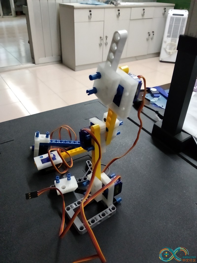
1Build the arm by servos and Legos.
Print some shapes to connect Lego and servos.
![]()
connect servo parts to build a sample 3DoF robot arm.
![]()
Extend it to a 7DoF robot arm.
-
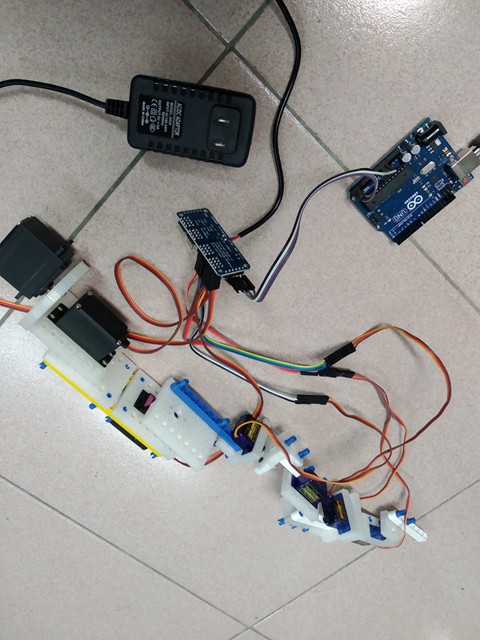
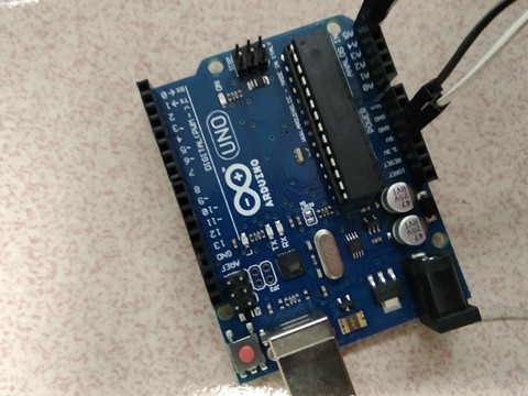
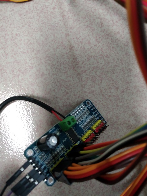
2Prepare an Arduino board and PCA9685 to drive servos
Connect the robot arm servos and Arduino via PCA9685 which need an independent 6V power. ![]()
Check Arduino pin A4 -> PCA9685 SDA , pin A5->PCA9685 SLC. GRD -> GRD, 5V->5V
![]()
![]()
-
3Set up a URDF model of the arm in your computer
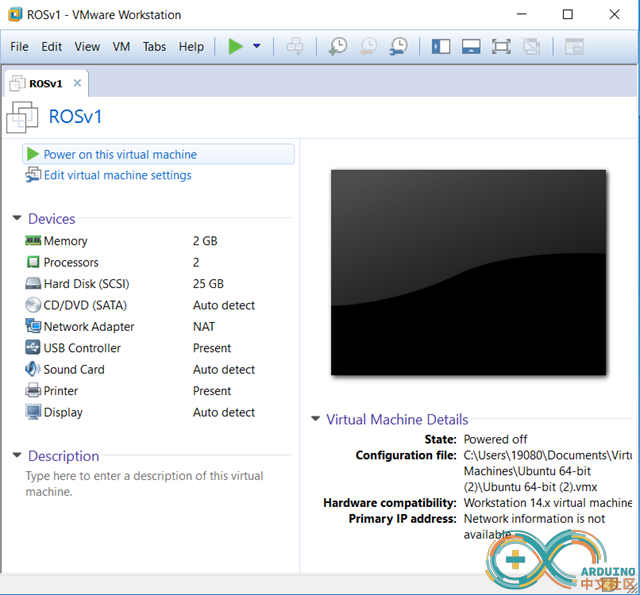
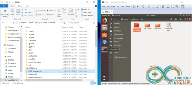
Prepare an Ubuntu Linux virtual machine and install ROS.![]()
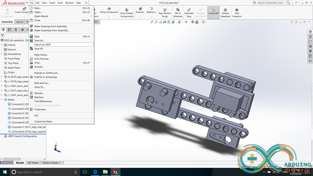
Install URDF plugin to Solidworks.
Build a robot arm in Solidworks and Export to a URDF file.
![]()
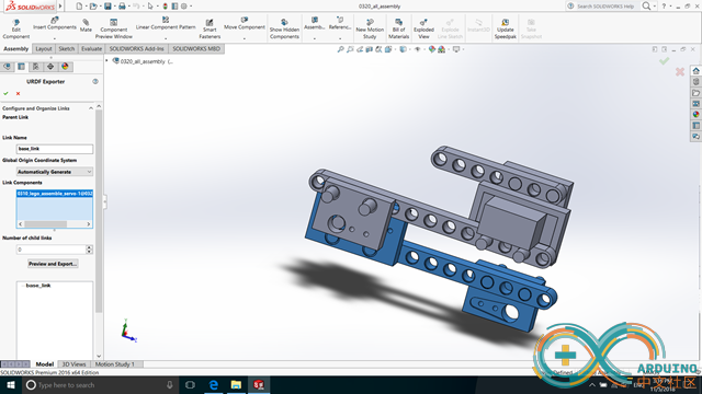
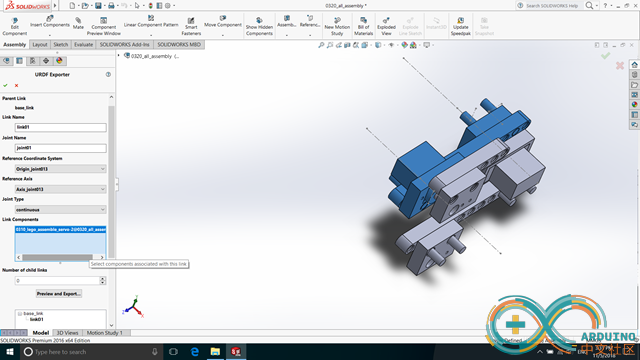
Set up every link
![]()
Press button "Preview and Export" to generate joint configurations.
![]()
Save the project and copy the file folder to Linux ROS catkin workspace.
![]()
Check the folder as a ROS package.
roslaunch urdf_tutorial display.launch model:=<the robot arm filename>.urdf
![]()
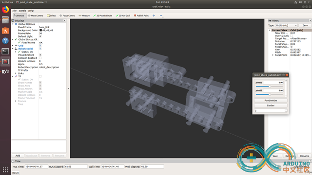
move the model by joint_state_publisher
![]()
It works.
So, extend it to a 7DoF robot arm model.
-
4Config a moveit node for the arm to feature motion-planning ability
The following instruction references http://docs.ros.org/kinetic/api/moveit_tutorials/html/doc/setup_assistant/setup_assistant_tutorial.html
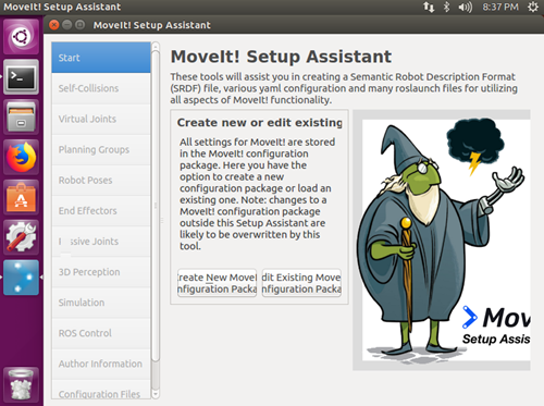
(1)To start the MoveIt! Setup Assistant
roslaunch moveit_setup_assistant setup_assistant.launch
![]()
(2) Load the urdf file.
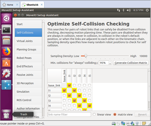
(3) Set up the configures of self-collisions, virtual joints, planning groups, etcs.
self-collisions:
![]()
config the virtual joint as : child: base_link, frame: world, type: fixed because our robot type is an industrial arm.
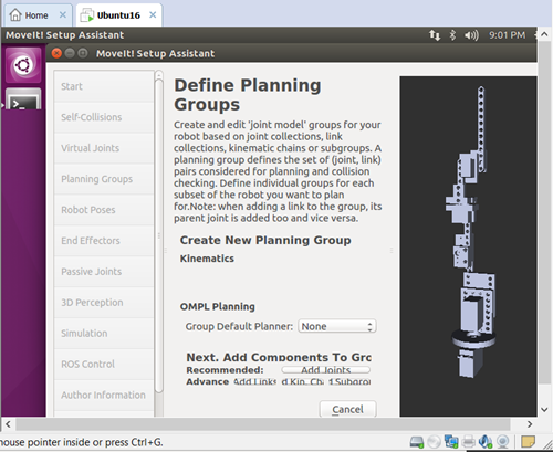
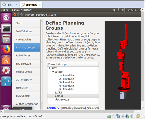
planning group: ![]()
![]()
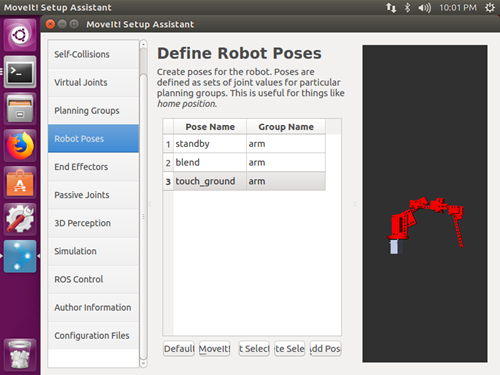
poses:
![]()
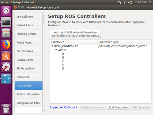
ros_control:
![]()
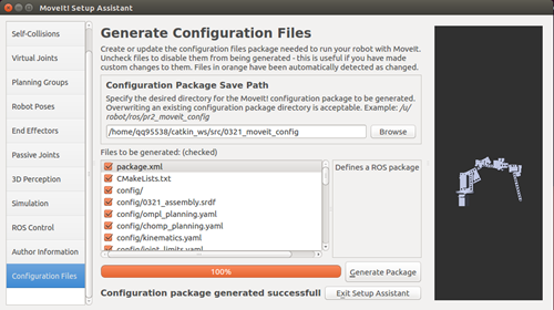
(4) Generate the configuration package.
![]()
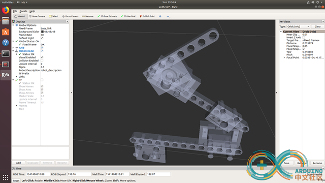
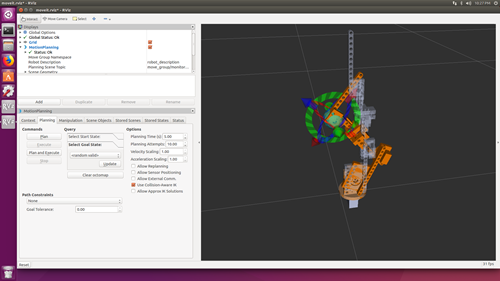
(5) Examine the configuration
> cd catkin_ws/src/0321_moveit_config/launch
> roslaunch demo.launch
to start RViz:
![]()
yes, the motion planner for our robot arm works.
-
5Code a ros-control node with Arduino to control servos of the arm
-
6Calibrate the robot
An Arduino Arm for ROS, wait a medical usage.
I read opensurgery.net, and have a doubt. can we make some kind of surgery robot with maker utilities?

Discussions
Become a Hackaday.io Member
Create an account to leave a comment. Already have an account? Log In.