 Dilshan Jayakody
-
1PCB fabrication and soldering
The PCB design which I provide is based on 2 layers and because of that, it's advised to build this PCB using some PCB fabrication service.
After fabricating PCB, you can start soldering the components into it. At first, try to solder SMD ICs. After soldering all 3 ICs next start with small SMD components such as resistors, capacitors and SOT-23 transistors. I highly suggest installing seven segment display, DC jack base, battery clips and terminals header at the last stages of the soldering.
-
2Upload firmware into the system
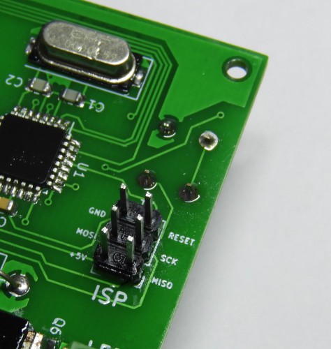
Once all the components are assembled the next task is to feed firmware into the microcontroller. To upload the firmware the most recommended method is to use AVR in-circuit programming (ISP) compliant adapter.
This system is designed to work with standard 6-pin AVR ISP interface and there are plenty of programmers are available for this interface.
During my prototype assembly, I used a USBasp programmer to flash the microcontroller with firmware.

During the firmware upload process pays extra attention to ATMega8 fuse settings. To get intended results low-fuse byte should set to 0xEF and high-fuse byte should set to 0xD9. For more details refer project documentation at the GitHub.
While using ISP make sure to disconnect the 24V power supply from the system.
-
3LED module
After uploading firmware, the only remaining task is to connect the LED module into the controller.
Before soldering 7W LED module, fix it to the provided heatsink. To improve thermal transfer make sure to apply thermal grease between the LED module and heatsink.
While LED lighting for long hours its temperature increase up to 70°C - 80°C. Because of this, make sure to take necessary action(s) to isolate the LED wire line with temperature. To overcome this, in prototype build I drive this wire through a high-temperature resistantBasalt sleeve.
-
4Using the light controller
At the first power up light controller starts with default settings. To modify those settings hold down “MODE” button for a few seconds and then it opens the System menu.
System menu consists of 4 options such as “SYS”, “ON”, “OFF” and “--”. You can modify the value associated with each option by pressing the “MODE” button. In System menu press “UP” or “DOWN” buttons to navigate over the available modes.
In “SYS” mode user can change the system time. Likewise in “ON” and “OFF” modes, the user can set the light on and off times respectively.
To leave the System menu, press the “MODE” button in “--” mode.
The light controller firmware is designed to switch to the idle state if the user is not involved with the system for a long period of time. In the idle state, seven segment display of the light controller is not active. In most occasions SLEEP indicator also got activate in an idle state.
The all options available in the light controller are explained with more details in the user guide available at the GitHub.
Programmable Light Controller
Low cost, easy to build, high power LED controller with a built-in programmable timer.

Discussions
Become a Hackaday.io Member
Create an account to leave a comment. Already have an account? Log In.