Matt Bradshaw
-
3D-Printed Prototype
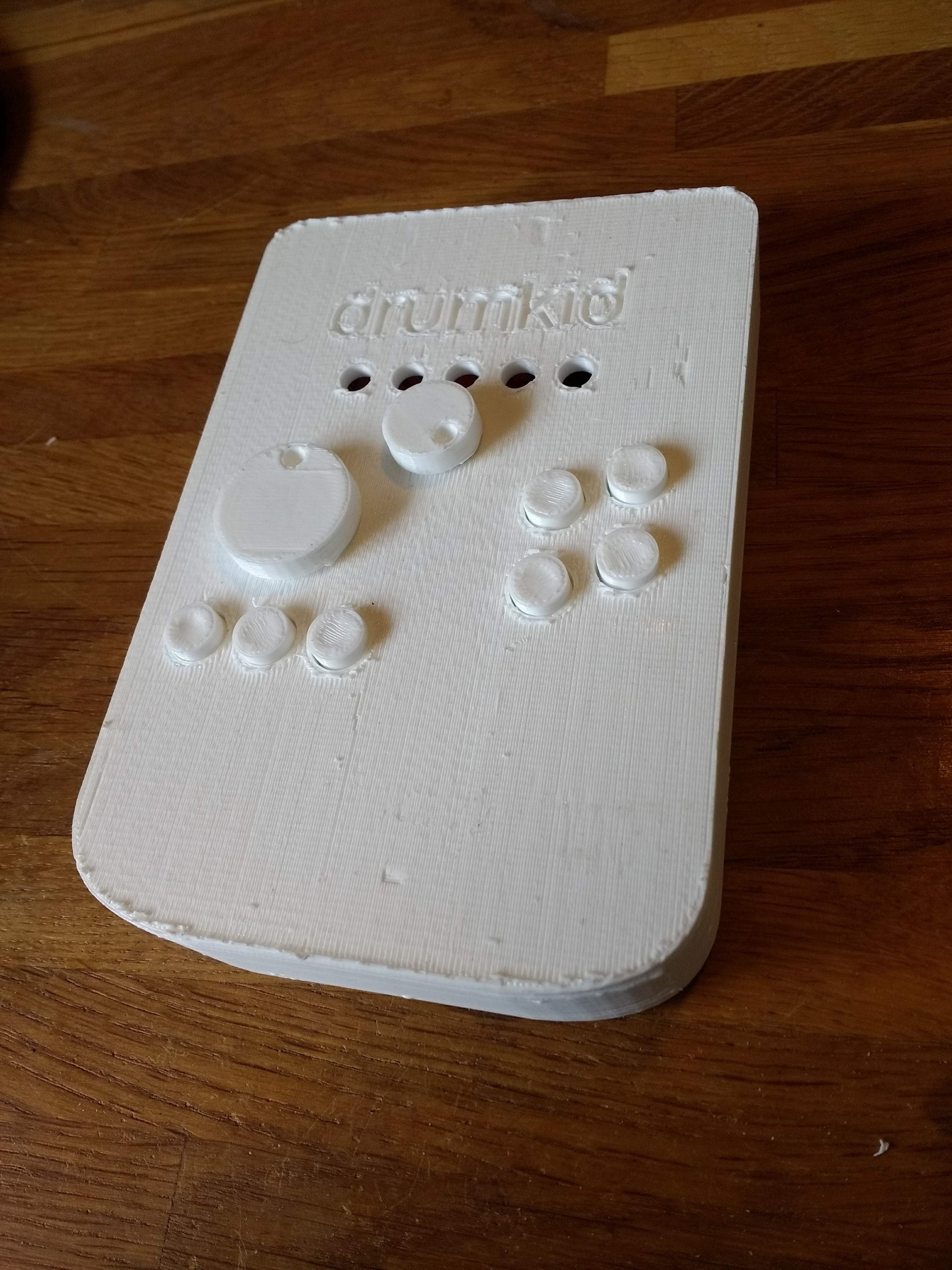
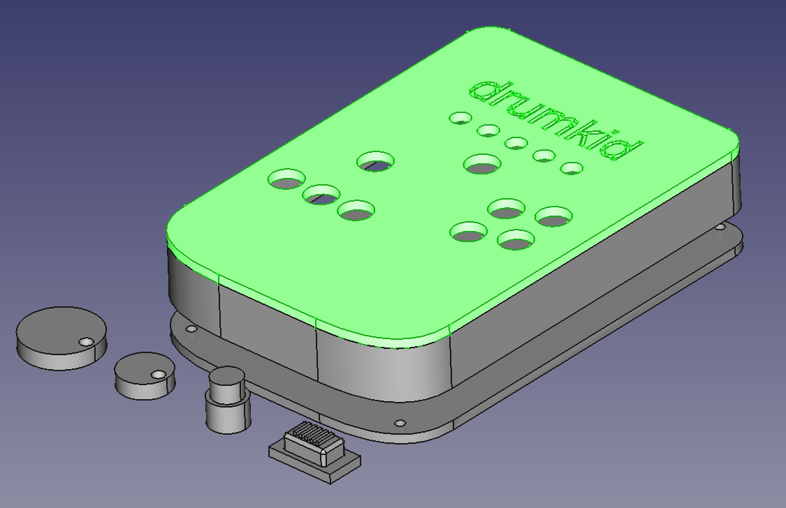
04/17/2019 at 15:56 • 0 commentsI've printed my first attempt at a case for DrumKid. It's still a long way from a finished instrument, but it's a great start - it feels awesome to see, hold, and use a thing that until recently only existed as a drawing. My current plan for the final product is to laser-cut the design as layers of wood, so I wanted to make a prototype which could theoretically also be made on a laser cutter. With this in mind, I used a uniform thickness of 3mm (which seems fairly standard on laser cutters) and didn't add any features that couldn't be build up in layers if need (i.e. the basic shape is a prism). Here's what it looks like from the front::
![]()
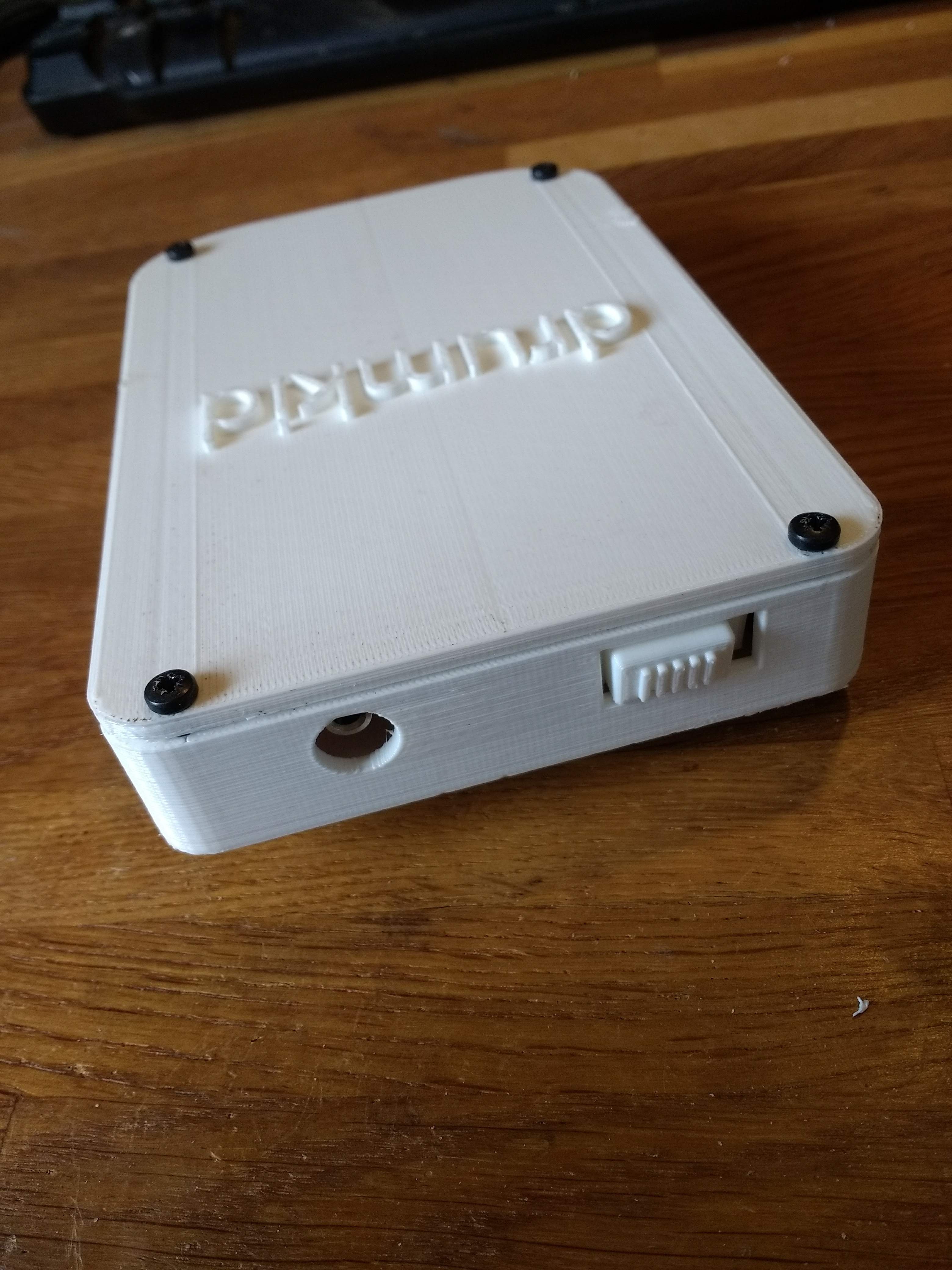
The finish is very rough because I printed the main part face-down, to avoid needing supports. For annoying reasons, my printer basically forces you to print everything on a raft, which is difficult to remove on larger prints like this, causing the pock-marked surface. I could avoid this in future by printing the case in sections, or by printing the other way up, with supports, but my priority for this build was speed. You can see a somewhat nicer finish on the back and sides of the instrument:
![]()
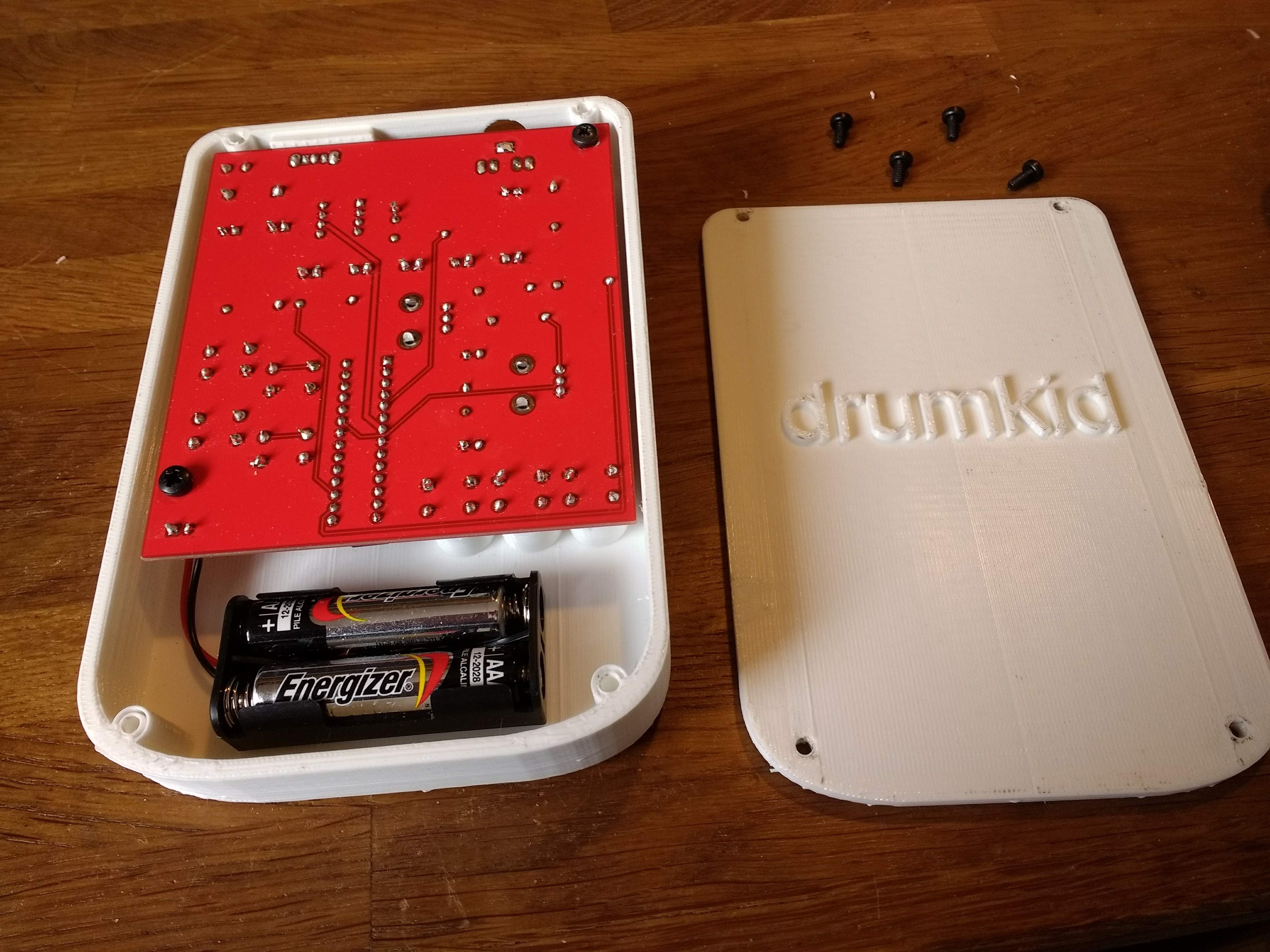
Here's what the case looks like with the back removed:
![]()
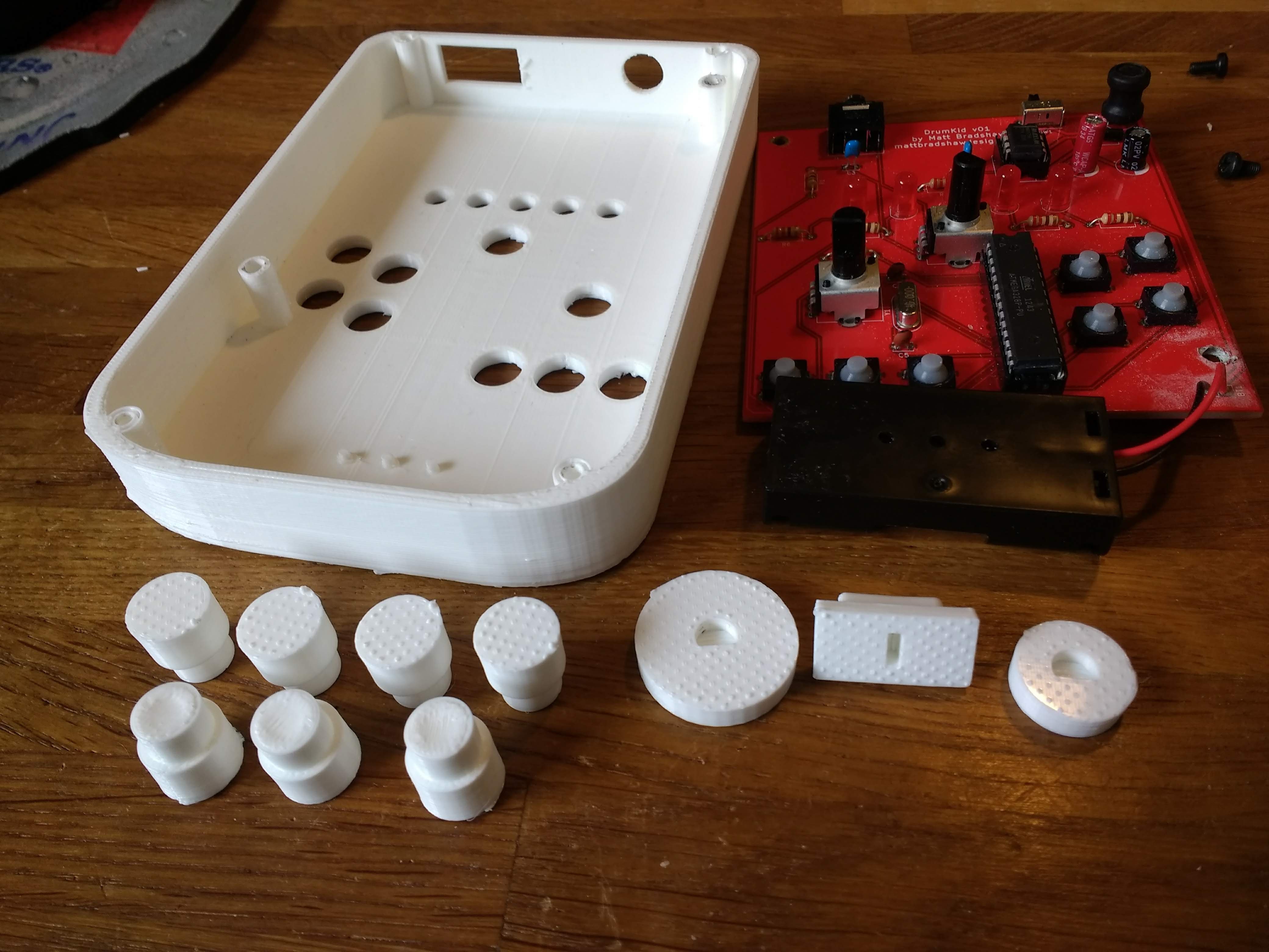
And here's what it looks like when entirely disassembled:
![]()
The plastic button plungers (is that the right word?) push down on the buttons on the PCB. Getting the correct dimensions took a bit of trial and error, but the buttons now work nicely. The chunky power slide switch also works well. The two knobs probably need a bit more work, but at this stage I wouldn't be averse to 3D-printing all of these small parts in the final product. They are quick to print and could look pretty cool if printed in a bright colour, contrasting with the look of the wood.
Printing everything took roughly 10 hours. I could optimise the design to print more quickly (and with a better finish), but it will probably never be quick enough to be viable for the final product, which is the main reason I am looking at laser-cutting.
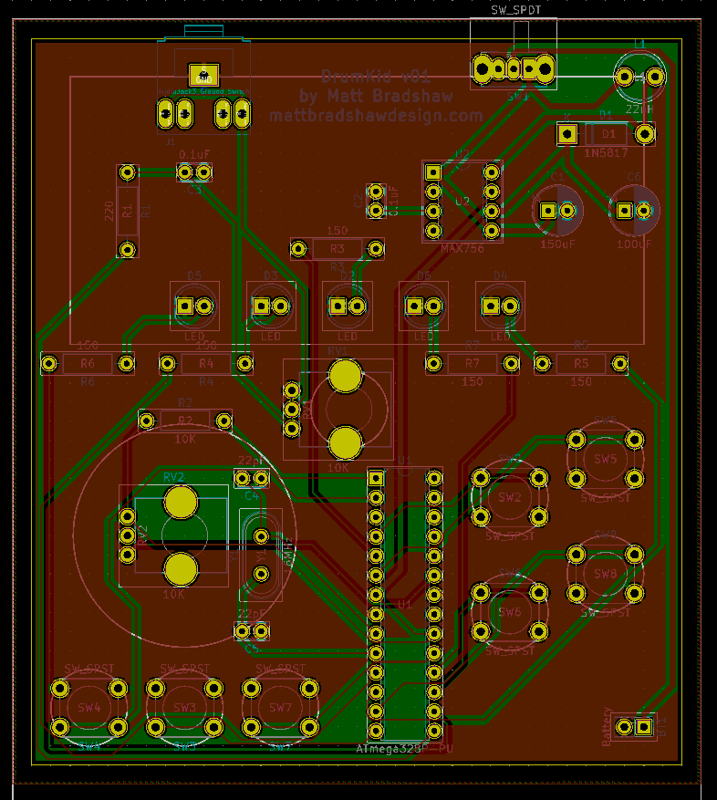
In case anyone is interested in how I designed the case, I used FreeCAD (which is free and open source). I sketched the design on paper first, then worked out the measurements of the lines and bezier curves that make up the outline. I drew this outline using "draft mode" in FreeCAD, then extruded it into a 3D shape. Almost everything else in the design is either a cylinder or a cube. Here's what the design looked like in FreeCAD:
![]()
Overall I'm really happy with progress so far. I've got a working PCB inside a decent, functional case, and I can now do some proper development work, iteratively improving the Arduino code to create a fun, intuitive instrument. However, there are a few things (besides those mentioned in my last log) that I have now realised I need to improve:
- The inductor and capacitor stick up too far from the PCB, meaning the board has to be mounted too far from the face of the instrument, preventing the potentiometers from protruding far enough through the top, and meaning that the LEDs are more recessed than would be ideal - mounting the tall components at right-angles, flat against the board, in the next version will hopefully solve this problem
- The PCB needs four mounting points, not two (it actually has none at the moment, but I drilled two holes for this prototype, thinking it would be enough) - more secure mounting gives a better feel when pushing the buttons
- The volume knob looks ugly and should be moved, either to the bottom-middle of the front, or alongside the power switch and headphone output
My next priority, though, is to spend some time adding features to the code. Hopefully the next log will contain an audio sample :)
-
First PCB Working
04/11/2019 at 10:05 • 0 commentsIt's alive!
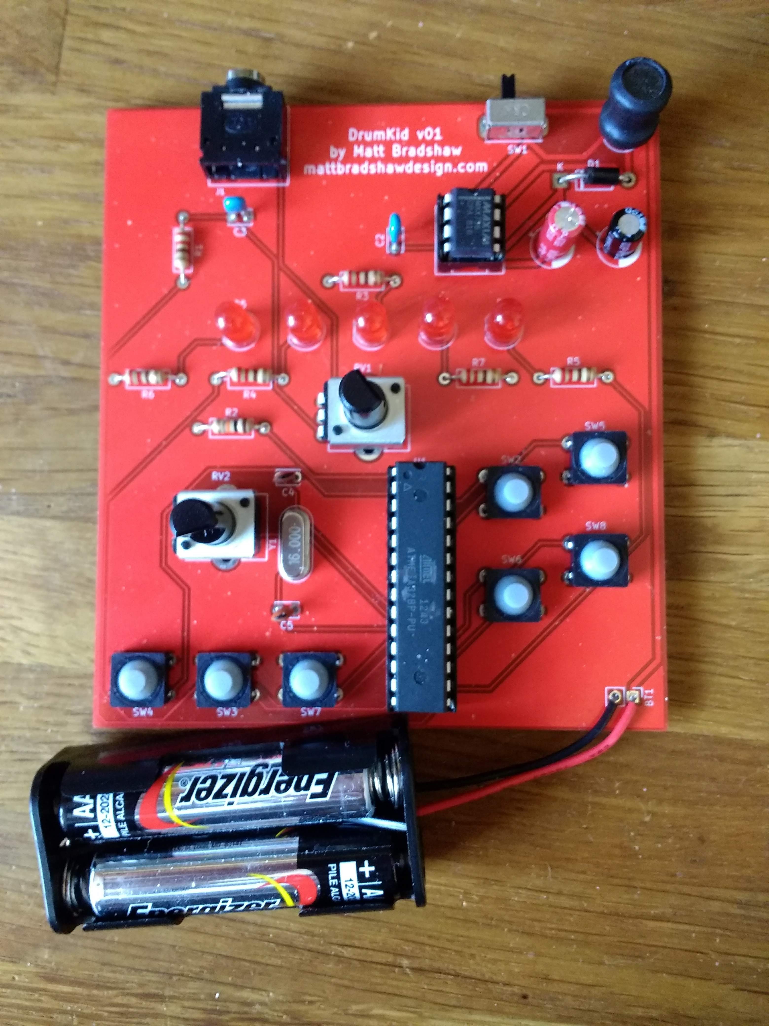
Ordered 10 PCBs from JLCPCB, which arrived while I was on holiday. They didn't seem to suffer from the postman having left them under the bench behind my house in rainy England for several days. I ordered a few remaining components and soldered everything in place.
![]()
Nervously, I turned on the power and... success! Well, almost. The ATMega328 runs fine from the two AAA batteries via the MAX756 voltage regulator, the LEDs work and the volume control works. Drum sounds comes out of the headphone socket, but the unwanted high-frequency noise from the breadboard circuit is, despite being quieter, still definitely present.
Knowledgeable people may be able to spot the problem simply by examining the photo of the PCB - I'm pretty sure that I need to add one or more decoupling capacitors close to the ATMega328's power pins. Powering the original breadboard design straight from 5V sounded fine, with the high-frequency noise only appearing once I employed the batteries and voltage regulator, so the problem was almost certainly a noisy power supply.
After some haphazard googling, I realised that adding capacitors would likely clean up the 5V signal and therefore solve my problems. I tried adding some capacitors to the breadboard design, and the noise was instantly and dramatically reduced, which was a big relief. I don't know of a good way to bodge several capacitors into this PCB, plus there are a few other imperfections, so I think I'll make a second revision, which might even end up being the final version if I'm lucky.
Here are my current thoughts for a second revision:
- Add decoupling capacitors - maybe even leave holes for more capacitors than anticipated, so I can experiment with different arrangements of multiple decoupling capacitors (apparently different values of capacitors in parallel will suppress different frequencies of noise)
- Move the voltage regulator closer to the microcontroller to further reduce noise
- Move the headphone socket (and power switch?) closer to the edge of the board - this will make case design easier
- Move the capacitor which is currently directly behind the headphone socket, so that I don't bend it with my thumb every time I plug in my headphones
- Rotate the potentiometers, which are currently mounted sideways (idiot)
- Add mounting holes, preferably in Lego-friendly dimensions to improve hackability
- Possibly add "breakout" holes either side of the ATMega328, partly to aid debugging/design, but also to make the design more hackable by others (e.g. breaking out the RX/TX pins would enable a hacker to add MIDI input/output)
- Maybe even leave space on the top panel for optional MIDI in/out sockets
- More/better labelling - add component values, maybe label the ATMega328 pins with their Arduino pin names, and maybe also add some fun graphics because why not?
For now, though, while I've got a working (if noisy) PCB, I'm going to concentrate on case design, because I'd like to know if there are any problems with the layout of buttons and knobs before I design a new PCB. Here is my rough plan for the next couple of weeks:
- Design and 3D-print a simple case for DrumKid - the final product is now unlikely to be 3D-printed (probably made of laser-cut wood layers instead), but 3D-printing will allow me to rapidly test/iterate the dimensions/ergonomics
- Do some more work on the code - the current Arduino sketch which is loaded onto the ATMega328 is really just a proof-of-concept, designed to test whether the buttons, knobs, scheduled sample playback and audio effects work properly. The "aleatoric" element, which is really the heart of the DrumKid concept, has not yet been implemented, so this is a good next step - adding this, in conjunction with a basic case, will give me a first proper, testable prototype which I can try out with my band
- Design the second version of the PCB and order it
-
PCB Design
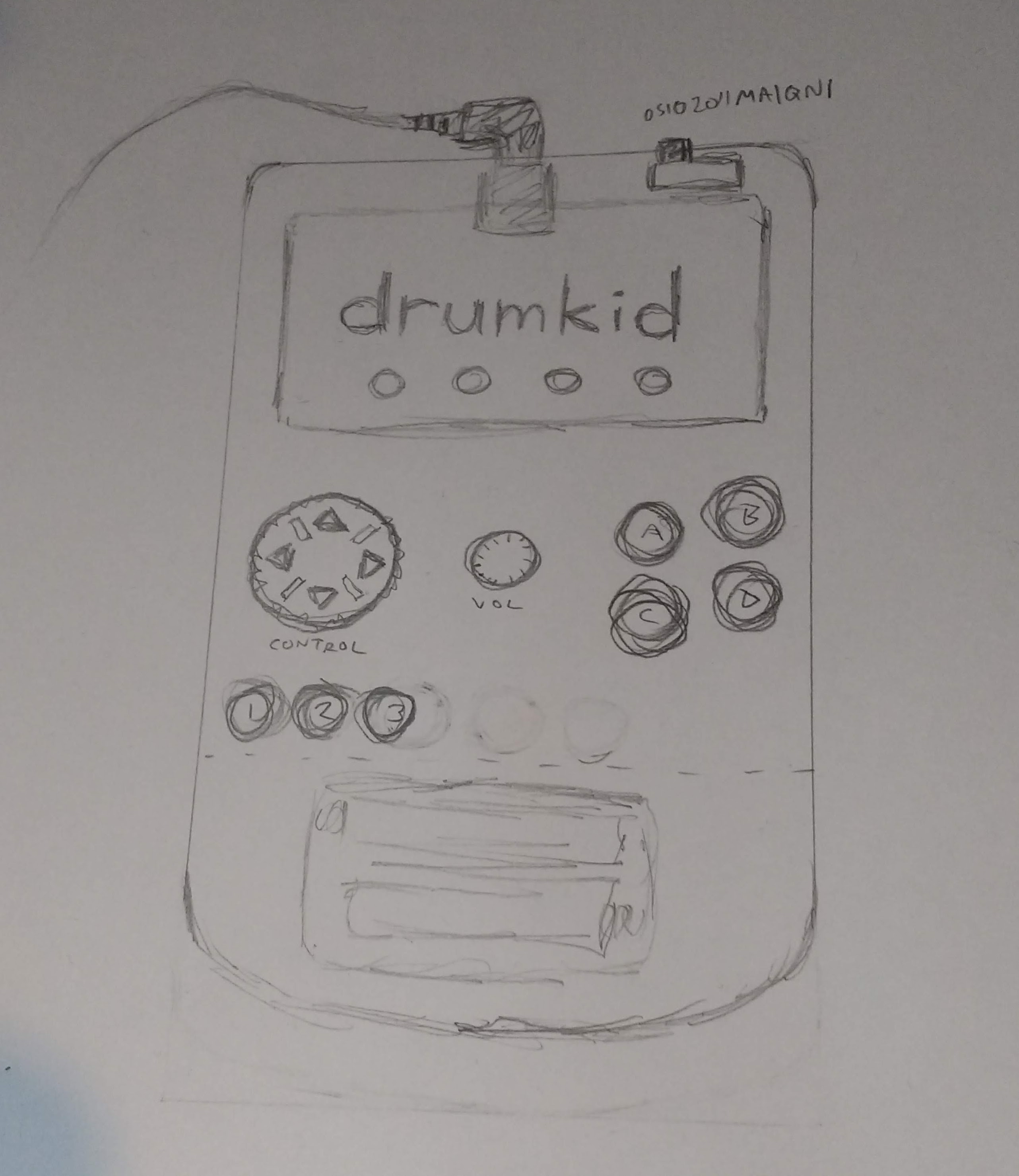
03/23/2019 at 02:09 • 0 commentsQuite early on in the process of designing this version of DrumKid, I hit upon the idea of making it look like a handheld games console, or possibly a game controller. I thought this would make it easy to play, and would give it a fun aesthetic. I sketched a simple design, tried to imagine playing it, made a few adjustments, and finally settled on it.
![]()
Rough sketch of DrumKid - the thing that looks like a directional pad is actually a knob, and the "screen" is just for show, not really a screen The design would allow me to keep the PCB below 10cm by 10cm, which keeps the cost down, with space to spare for a battery compartment at the bottom.
I'm pretty new to KiCad. I've only designed one previous board (a timer with an LED display), but it did end up working, so I was optimistic about being able to design a decent PCB for DrumKid. In case anyone's interested, I learnt KiCad from Shawn Hymel's excellent YouTube series:
While creating the schematic in KiCad, I realised that I was only using 9 of the Teensy's 20 pins, and in a fit of immaturity decided to add five LEDs to the PWM pins. My reasoning was a) they might be useful for visual feedback, b) LEDs look cool, and c) if I decide not to use them, I can just not solder them and I don't even have to revise the PCB - win-win!
![]()
My second-ever PCB design - this has already been sent off for fabrication, but please let me know if you see any obvious mistakes because I'm new to this! Anyway, I made the schematic, laid out the board, generated Gerber files and sent the design to JLCPCB. I'm off on holiday for a week, but hopefully the boards will arrive not long after I'm back, at which point I can solder everything in place and see if it works.
-
Breadboard Prototype
03/23/2019 at 01:21 • 0 commentsI already put quite a bit of effort into developing the DrumKid concept while it was just a web app, and got it to a state that I'm pretty happy with. Once you've got the hang of playing it, it's a fun, interesting device that can be controlled even while playing another instrument. This meant that the development process for the Arduino DrumKid was mainly about the practicalities of transferring a screen-based web app, running on a powerful computer, to an Arduino with some buttons and knobs.
I quite quickly settled on Mozzi as my Arduino audio library of choice, because I've used it before and was impressed with it. It's relatively lo-fi, but then the original DrumKid happened to produce lo-fi sounding beats anyway, so that's fine.
I drew up a list of initial specifications for the device that looked something like this:
- Should be cheap to build
- Should be small and portable
- Should run off batteries
- Should be easy to play
- Should look cool
Once I'd got a basic drum beat playing on an Arduino Uno, with a few simple effects controlled in real time, I knew that the software side of the project was viable, and decided to put my effort into hardware design instead.
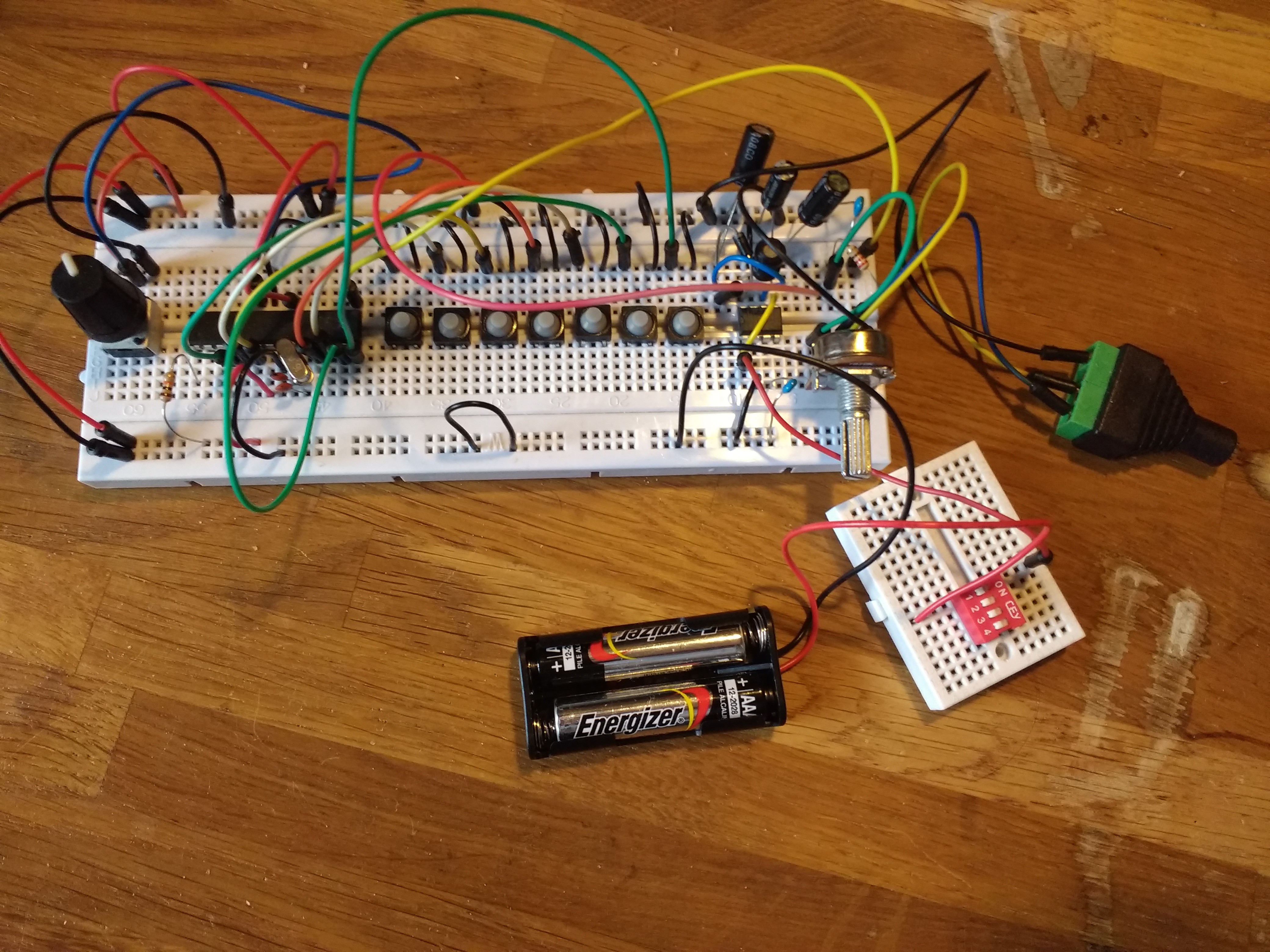
I made a homebrew Arduino Uno on a breadboard, knowing that this would be the basis of the final PCB. This is simpler than it sounds - you just yoink the big chip out of an Uno, put it on a breadboard, add a crystal and a couple of capacitors and hook up 5V and ground. Doing this takes the cost of the "Arduino" part of the project down to about £4.
Next I added buttons, potentiometers, and headphone socket. I tested the circuit with a 5V power supply, and it worked! But then I started thinking about battery power, which was something of a rabbit hole. The breadboard Arduino needs a fairly precise 5V power source. The simple, cheap option would be a linear regulator, but these waste a lot of energy and require 7V or more to work properly. This would mean I could either power DrumKid with a 9V battery (which would be dead very quickly) or 6 AA/AAA batteries, which is a silly number of batteries for such a simple device.
I was looking for a voltage regulator chip which was cheap, efficient, easy to solder (i.e. through-hole), and which wouldn't require too many batteries. Eventually, I stumbled onto the MAX756 chip, a step-up chip which could happily output 5V from two AAA batteries. It cost £4, which is about ten times more than a linear regulator, but the rest of the project was working out pretty cheap so I decided it was worth it.
![]()
After a frustrating few hours of misunderstanding the MAX756's datasheet, I finally got a stable 5V out of it. I hooked it up to the rest of the DrumKid test circuit on the breadboard, and had a moment of simultaneous excitement and frustration. On the one hand, I was successfully running DrumKid from two AAA batteries, using only about £10 of components in total. On the other hand, there was a weird, high, badly-tuned-radio noise that hadn't been present when I used a "proper" 5V power supply.
At this point, perhaps stupidly, my optimism took over. While trying to get the MAX756 to work, I had found several people mentioning that it was very sensitive and wouldn't work properly on a breadboard. Someone who attempted a breadboard circuit with a MAX756 was derided on Stack Exchange for his "long loops of jumper wire", which were not only present in my circuit, but which caused the weird noise to change when I touched them. I decided that, in the absence of a more sensible plan, I would push on and design the PCB, in the hope that when I added the components, the noise would be magically gone. And that's where I've got to so far...
Next up: PCB design, ordering/testing the PCB, and (if all goes well) designing a case.
DrumKid: aleatoric drum machine
A lo-fi digital drum machine which uses randomness to create unpredictable beats. Runs on Arduino, with audio provided by the Mozzi library.