Close
0%
0%

Pixel Badge (Shitty Pixel)

An oversized WS2812 conference badge and add-on

Similar projects worth following
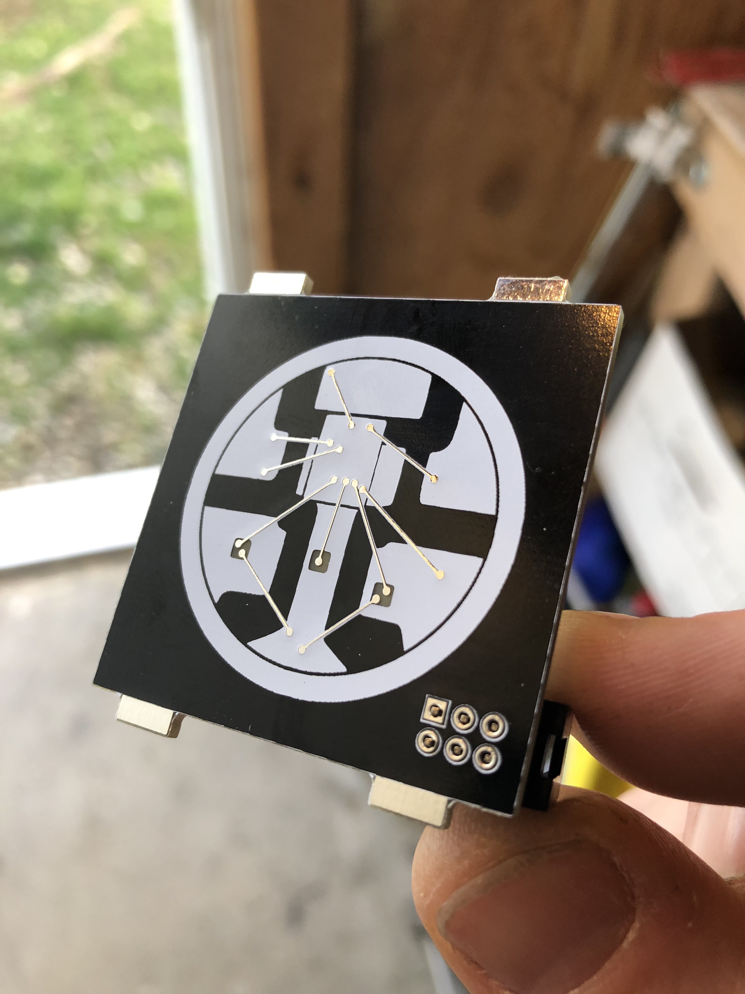
A conference badge and SAO meant to look like a big WS2812 led.

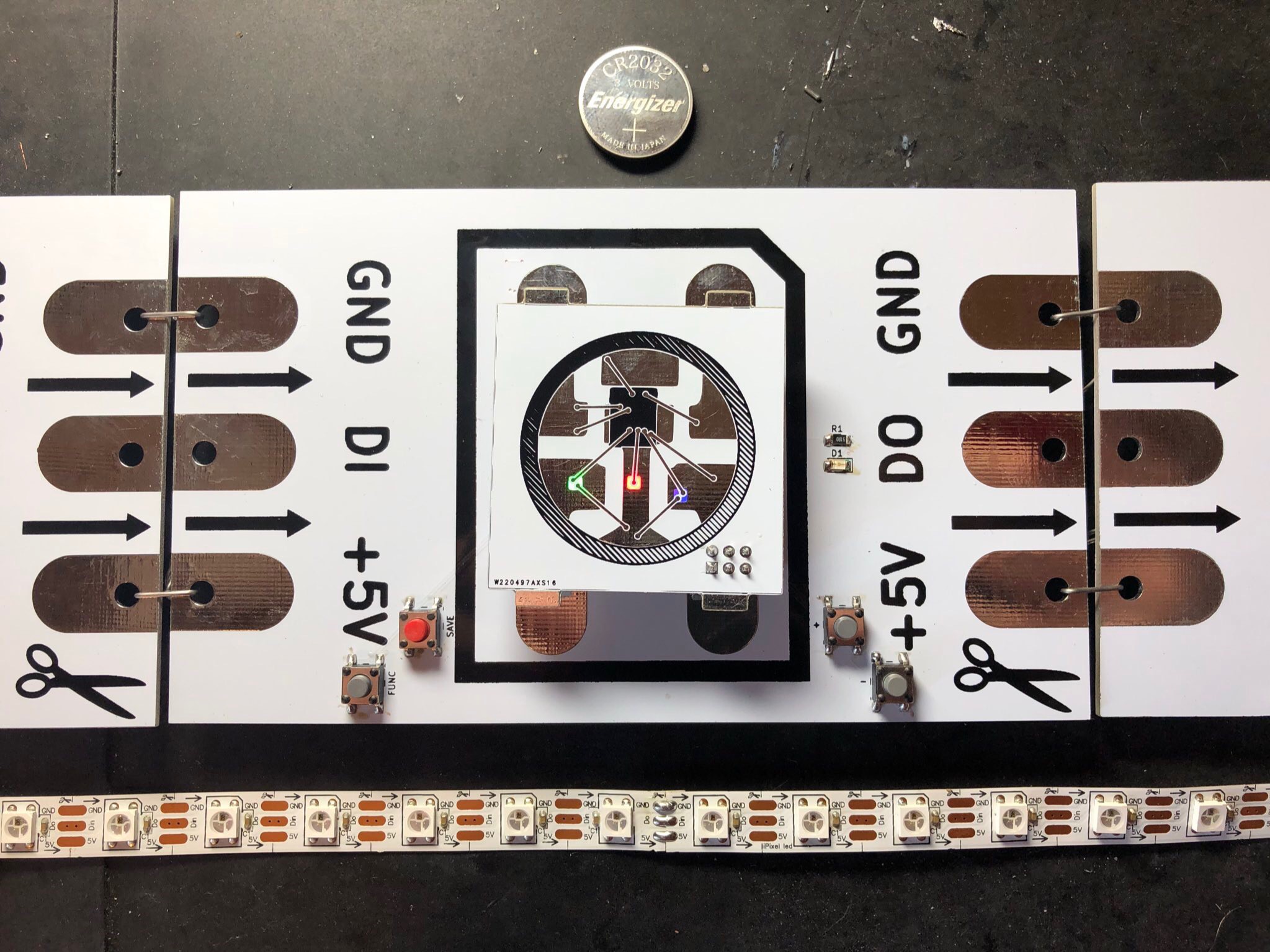
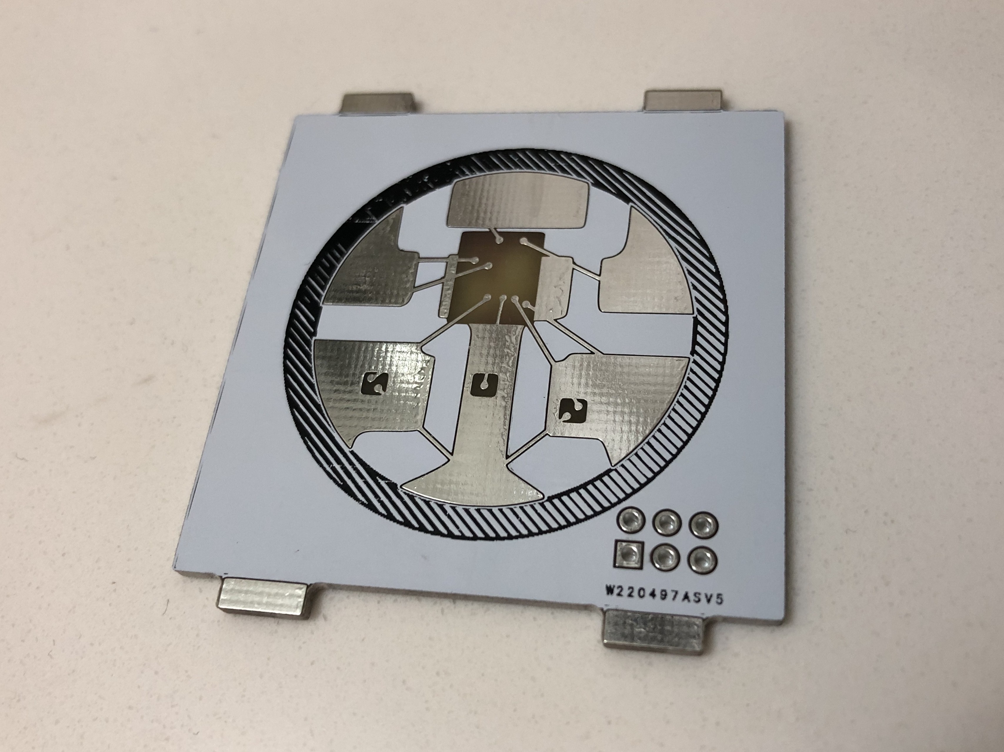
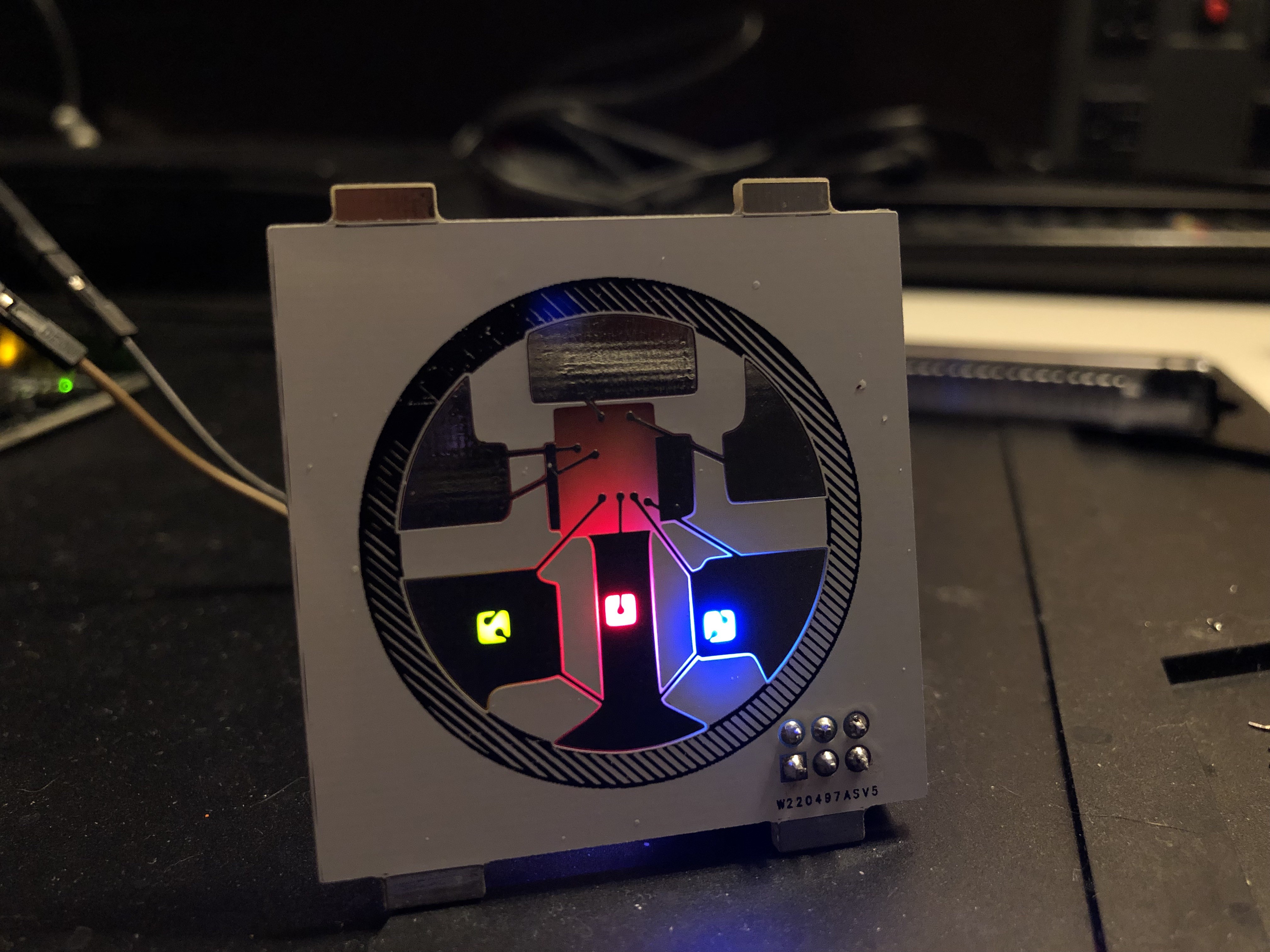
Working on a shitty add on for Defcon 27 utilizing shitty add-on standard v1.69bis. The goal is to have an oversized version of a WS2812 led that can change colors based on commands issued over i2c. By default it will cycle through some animations on it's own by just applying 3.3v, but there will be more to unlock with the appropriate commands. 

Features

This shitty add-on has a mediocore ammount of features built in!

  • 3 individually controllable LEDs!
  • A microcontroller! 
  • EEPROM!
  • Between 3 and about a dozen (maybe) built in LED animations!
  • Secrets! 
  • Control via I2C. Address TBD.
  • Is the artwork a feature?

Files

I removed all the files I had uploaded because things are in a constant state of change. After I make up my mind on what the final version will be, I'll upload everything here to share.

shitty_pixel.ino

ino - 17.26 kB - 08/18/2019 at 00:14

Download

shitty_pixel_schematic.png

Portable Network Graphics (PNG) - 34.32 kB - 08/18/2019 at 00:13

Preview

shitty_pixel-B_SilkS.gbr

gbr - 712.22 kB - 08/18/2019 at 00:13

Download

shitty_pixel-F_SilkS.gbr

gbr - 236.34 kB - 08/18/2019 at 00:13

Download

shitty_pixel-B_Cu.gbr

gbr - 109.06 kB - 08/18/2019 at 00:13

Download

View all 13 files

  • 1 × ATTINY85-20SUR Microprocessors, Microcontrollers, DSPs / ARM, RISC-Based Microcontrollers
  • 1 × CAT24C03WI-GT3 Memory ICs / EEPROMs
  • 1 × AP2331SA-7 Power Management ICs / Power Supply Support
  • 1 × XZFBB45S-9 LEDs and Accessories / Light Emitting Diodes (LEDs)
  • 1 × LS T776-R1S1-1-Z LEDs and Accessories / Light Emitting Diodes (LEDs)

View all 6 components

  • Pixel Badge is born

    blinkingthing08/04/2019 at 21:27 0 comments

    I was never completely confident that my 'Shitty Pixel' SAO would be fully functional with any Defcon 27 badges so I went ahead and made my own to guarantee it. 

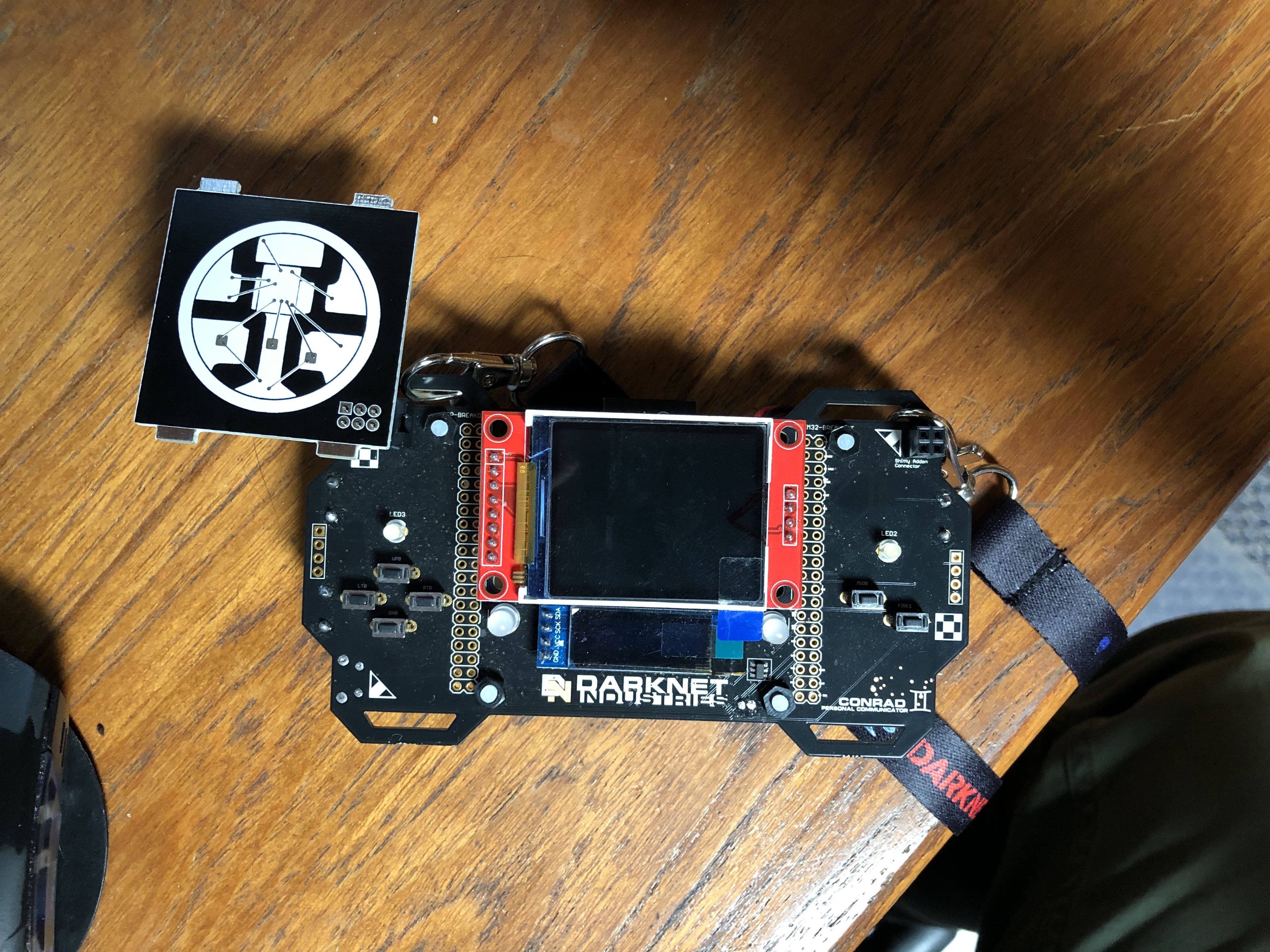
    With the Pixel Badge, you can change the animation, speed, and brightness level of the SAO. You can save the adjusted settings to EEPROM so they persist. The badge consists of a handful of buttons, an another attiny85, and indicator LED, power switch and battery holder. The microcontroller is installed in a socket, so it's removable if you want to reprogram it outside the badge although there are ICSP pads as well for use with something like this.

    The code for both the SAO and the Badge could stand to be improved, but are functional enough to be released into the wild. I will post the code after Defcon so anyone with a Pixel Badge or Shitty Pixel can hack on them.

    As it stands this is how the badge works:

    • FUNC : Changes current function (Animation Mode, Speed, Red Brightness, Green Brightness Blue Brightness)
    • SAVE : Saves current setting to EEPROM for persistance
    • + :  increases value
    • -  : decrease value

    When you press the FUNC button, the indicator LED on the Badge will flash n-1 times. n being the function's number on back of badge. (MODES = no flash, SPEEDS = 1 flash, RED LEVEL = 2 flashes, GREEN LEVEL = 3 flashes, BLUE LEVEL = 4 flashes.) 

    Saving to EEPROM gives no feedback. Just try switching it on and off again to see if it saved. 

    When left on overnight some of the pixels "locked up". When I reset the badge, they came back to life, not sure what happened but I've run out of time to revise the code. 

    Looking forward to Defcon and meeting some other #badgelife folk. See you in the Desert!

  • Assembly and Packaging

    blinkingthing06/03/2019 at 01:10 0 comments

    Assembly

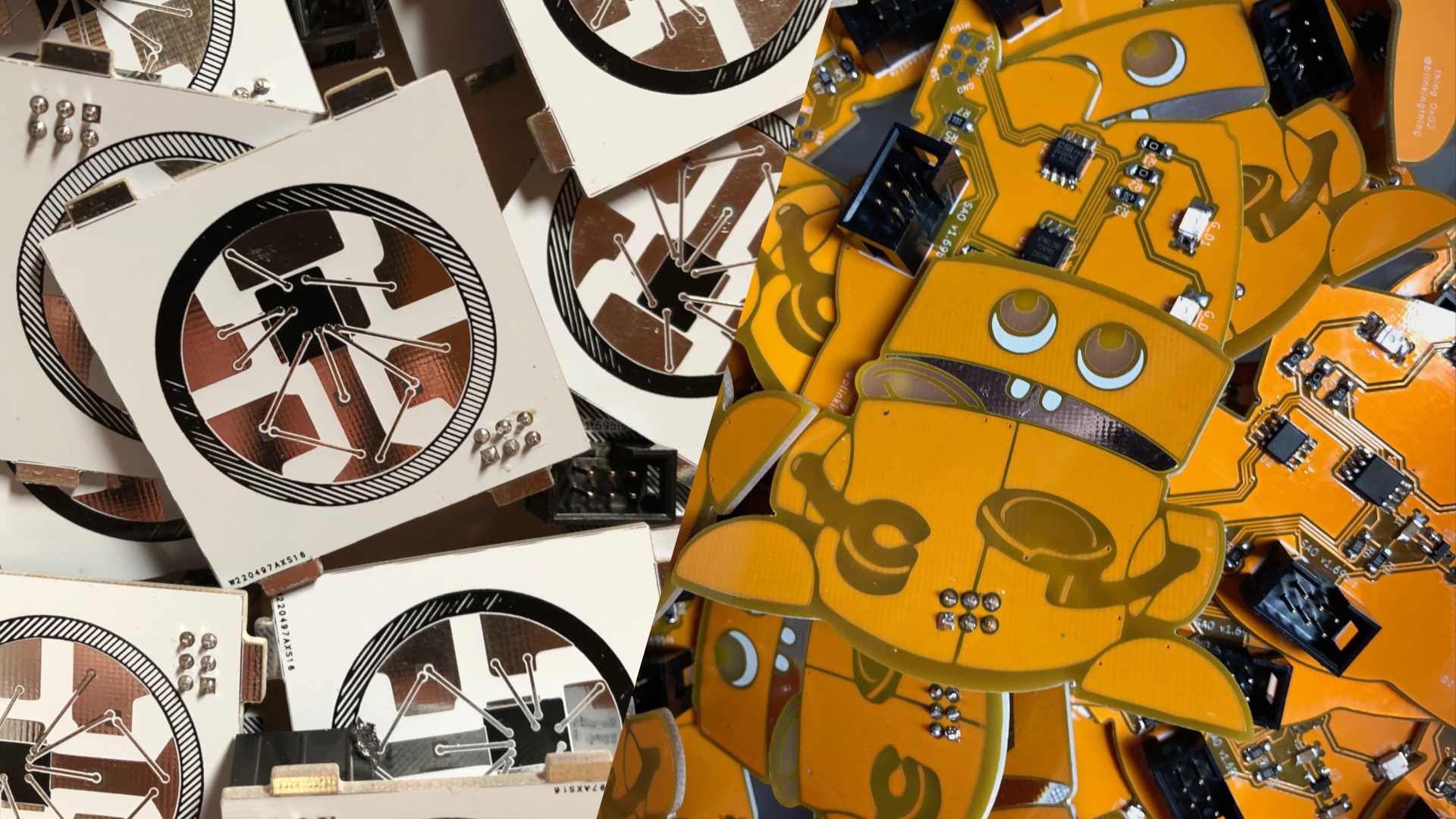
    I've been assembling Shitty Pixel and Robot Bank SAOs all weekend. I don't think I've mentioned it yet but I was simultaneously working on a few different SAO designs. I could only decide on two, so I'm using the same circuit from the Shitty Pixel for a second SAO, the Robot Bank. 

    I went through a few different trial order of operations trying to figure out the most efficient way to assemble the boards and then test, troubleshoot and fix the ones with issues. This is how I ended up doing it. 

    I lined up as many PCBs as would fit on my anti-static mat.

    Then I tinned at least one pad per component I would be placing. 

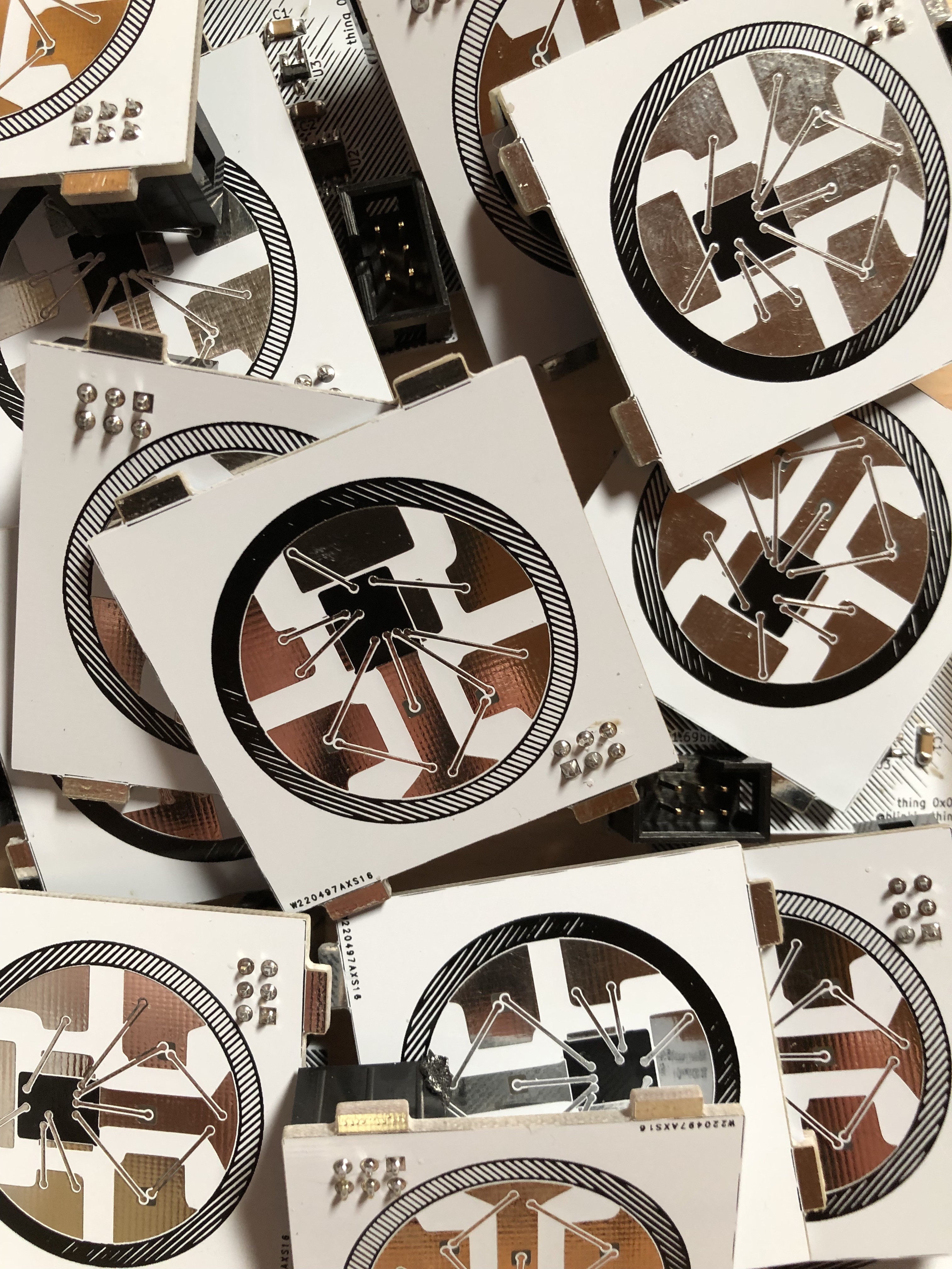
    Then I tack soldered one side of all the components I could comfortable place with the current orientation of my workspace. Once I completed everything I could from that position, I rotated the anti static mat 90º and placed the components that were in that orientation. After repeating this process two more times, soldering all pads along the way after components had been placed, I moved on to programming the boards. 

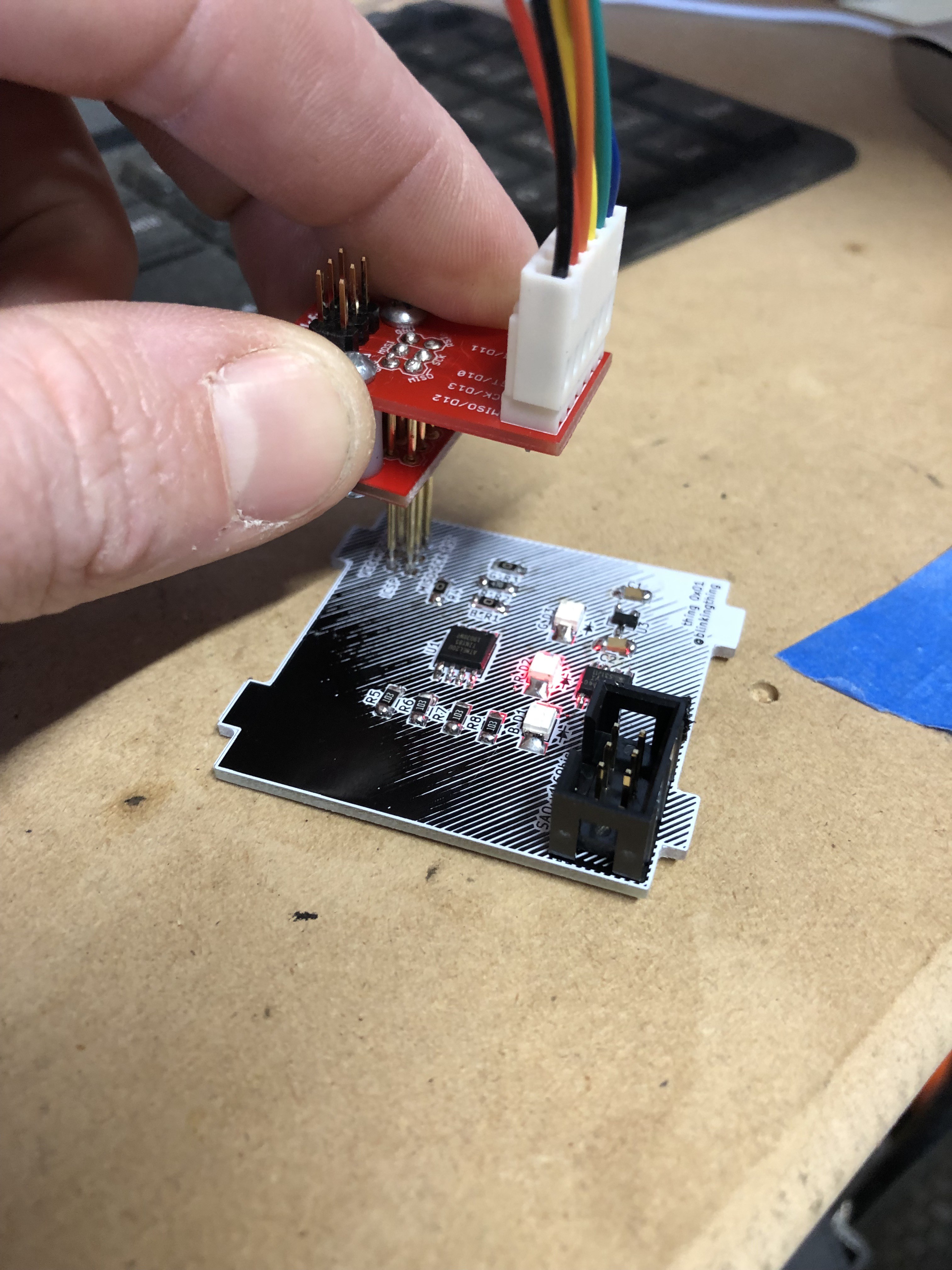
    This is where the ability to program the ATtiny in circuit was really valuable. I focused mainly on getting the hardware finished knowing that I could figure out the software at a later date. Now with the hardware in hand, I finished the last few bits of code and started uploading the code using the Arduino IDE and a Sparkfun Tiny AVR Programmer and Pogo ISP adapter kit. 

    This took a few mouse clicks and seconds of waiting per PCB burning the bootloader and programming the ATtiny with the arduino sketch. When the sketch is done being loaded, it automatically starts running and I could quickly see if it was running properly and I could check to see if all three LEDs were working.

    The next step on the assembly line is QC. Here I used the SAO Dev Board atop a raspberry pi to check the following:

    1. Does it power up through the SAO connector
    2. Check I2C bus for expected devices at expected addresses.
    3. Check I2C control of LEDs by activating modes other than default mode.
    4. Flash EEPROM with desired data using python script. Read back and verify EEPROM data.

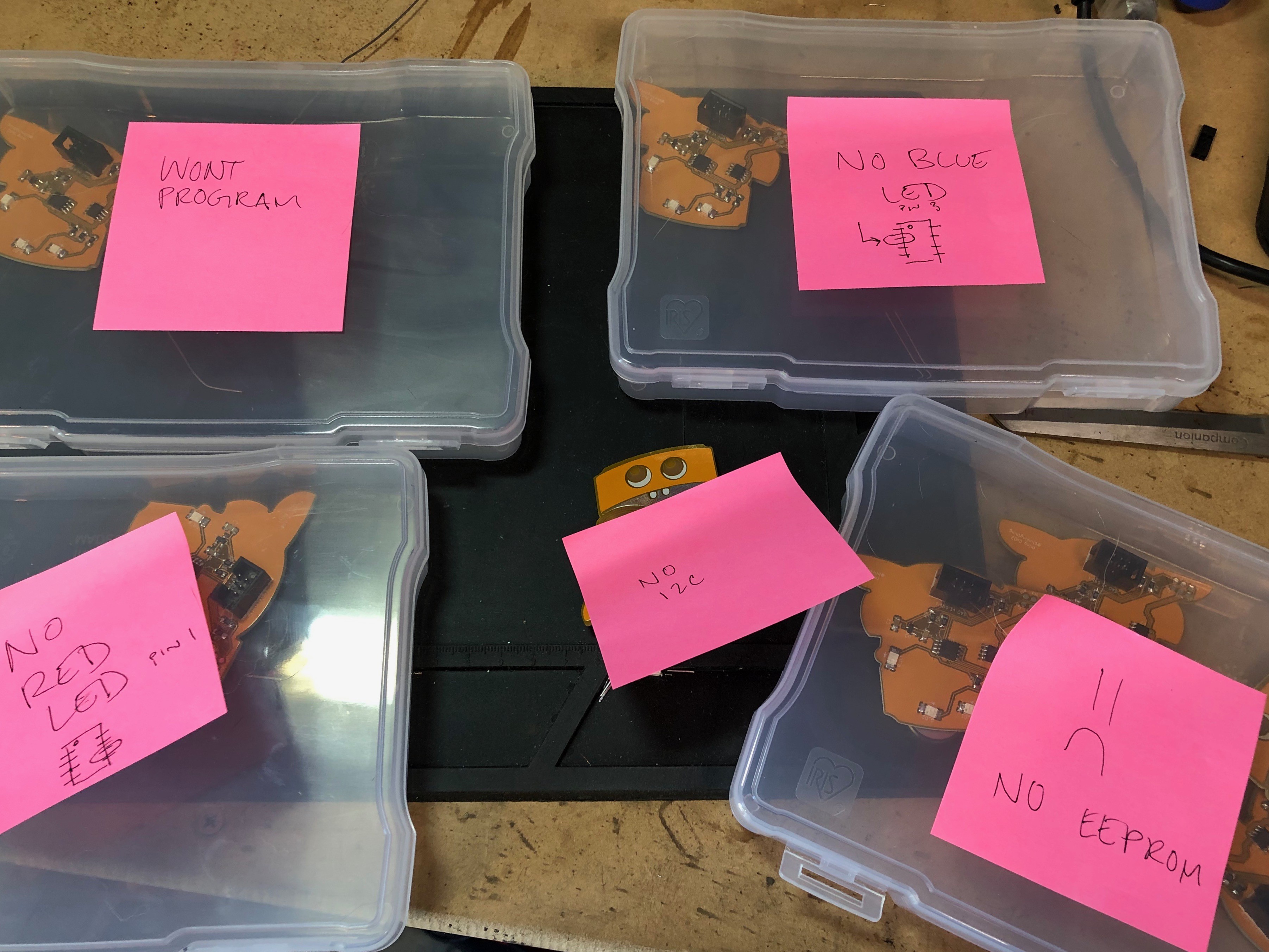
    If any of the boards failed any test, I separated them into different piles with similar problems so I could keep working through the pile of boards to be tested and I could troubleshoot later. I ended up using post its with notes, including tiny pin-out diagrams as cheat sheets for common problems that kept coming up. By far, the most common issue was the EEPROM chip not being detected on the bus and the second most common problem was not being able to program the ATtiny. Both these problems were caused by soldering errors by me. Hand soldering these small parts by hand with my naked eye has been a challenge. I do have a microscope that I've been using to get a better look at the troublesome areas, this is an extremely useful tool but slows me down a bit. So, I've been soldering the majority of the boards without magnification, only using it when I have issues. 

    After each PCB passes all my quality checks, I seal them up in the final packaging. 

    Packaging

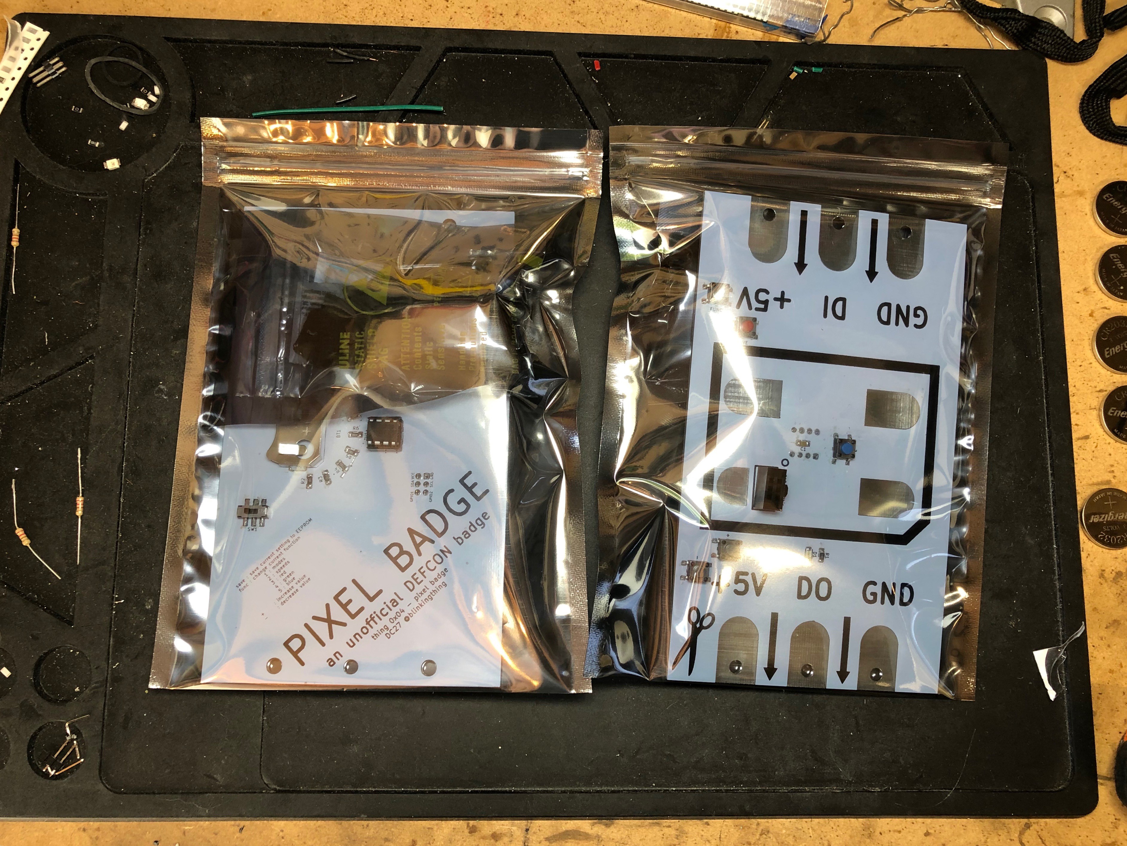
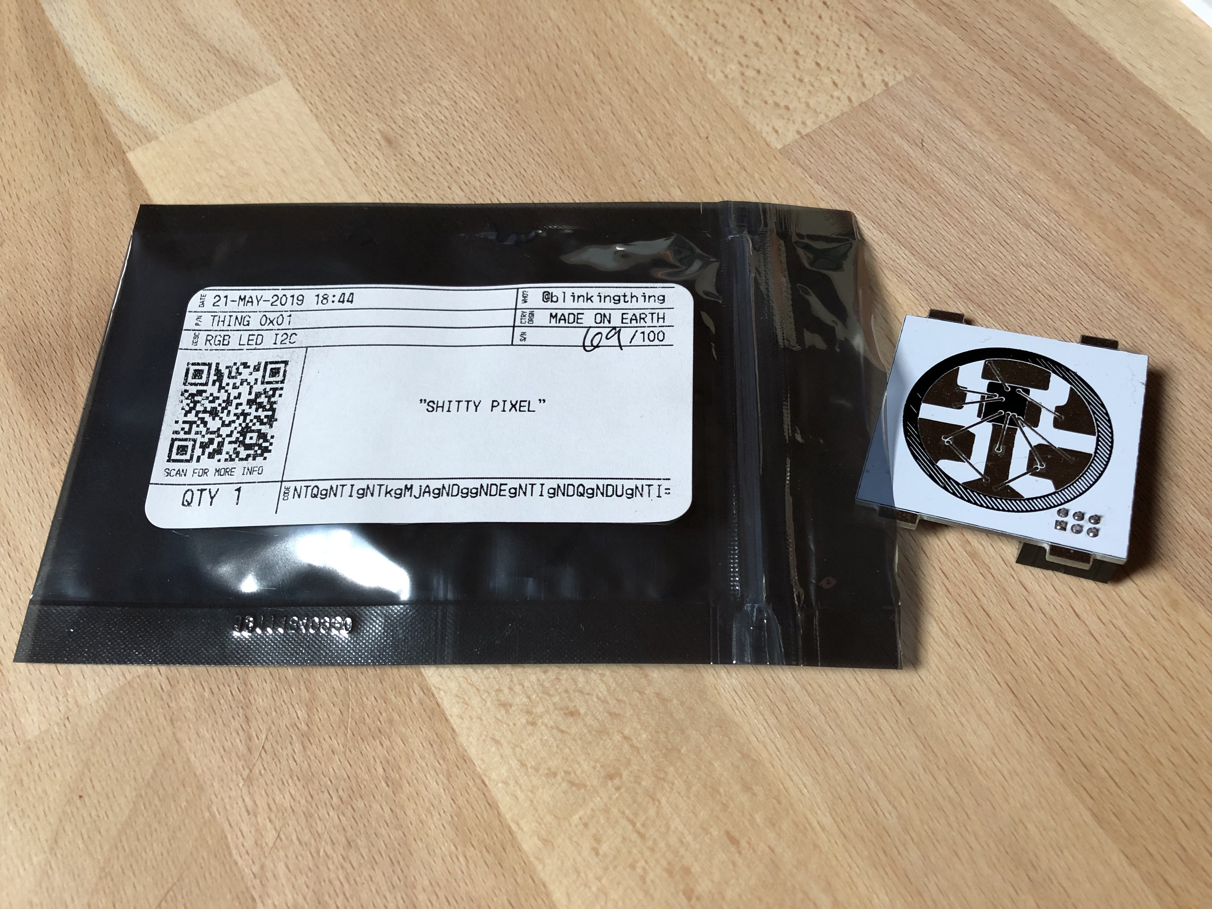
    I wanted to do something slightly more than just putting these SAOs in an anti-static bag so I designed some labels with a cipher and a QR code that links to a digital datasheet that I also designed. I basically wanted it to look like the labels on the envelopes all the Digikey components came in. Theres a few secrets and codes involved with my SAOs and the packaging gives you hints to find them and figure them out. I drew some inspiration from the Hack for Satan Badge from DC26 with the VHS box, I know that is completely different from what I've done, but it's nice to see attention paid to the packaging and I wanted to follow suit. 

    That's all for now. I have SAOs in stock now. Will add the Tindie link once they are approved for sale.  

  • I2C Control Demo / Progress Update

    blinkingthing06/01/2019 at 07:00 0 comments

    I2C Control Demo

    Progress Update

    I have all the PCBs and components in hand. Code is finalized and I have the first batch of SAOs ready to go. Tindie links incoming soon!

  • Nearing Completion

    blinkingthing05/17/2019 at 17:56 2 comments

    Hardware

    I'm learning a lot throughout this process, and for the most part it's been a positive experience. I keep missing things or finding out there's an angle from which I should be looking at things that I didn't even know existed. But hey, nobody knows everything, and nobody is perfect, and it only costs $23 to get another set of prototype boards manufactured and shipped here from PCBWay. 

    I thought I was finished with the circuitry when I succesfully added the ICSP programming pads, but then I caught a twitter post by @Nick Sayer suggesting the #badgelife folk use an AP2331 between the SAO 3.3v bus and the power supply coming in off the badge. This will help protect the circuitry when hot swapping SAOs. This was probably unnecessary but I liked the idea of adhering to higher standards than the SAOs need in case I end up trying to produce some other circuitry in the future. 

    The addition of this power protection took 2 board iterations because I totally biffed the way I connected the bypass caps on my schematic. Sometimes I really just don't pay attention, or have a severe lapse in my ability to pay attention to details. 

    Somewhere between board revs 4-7 I also had to connect the SCK pad for the EEPROM chip that I somehow just neglected to connect to anything (I used a wire jumper in the mean time to make things work).

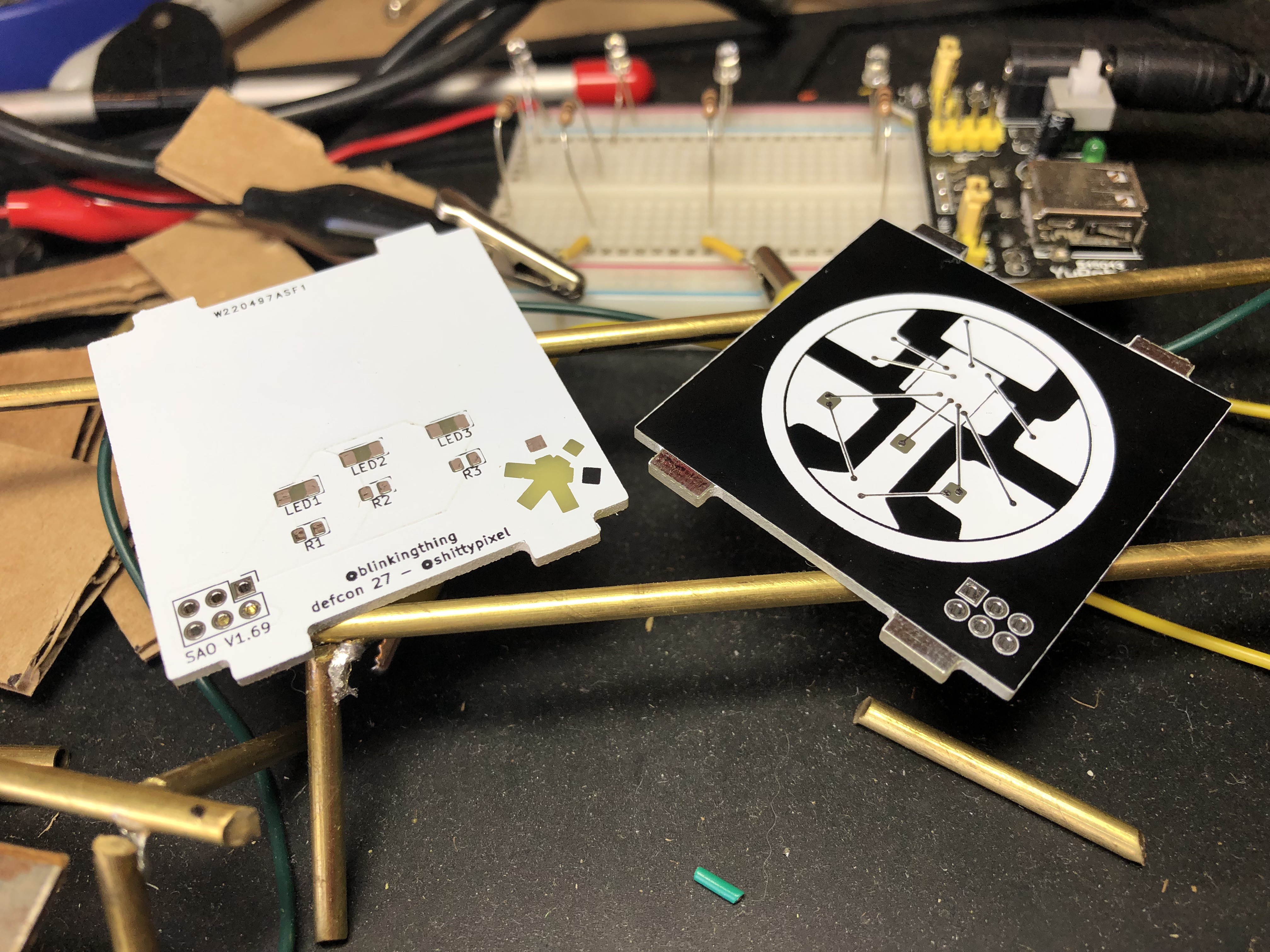
    For the latest iteration of the board, I also paid a little bit more attention to the actual layout of the parts. I grouped all the 10k resistors together, lined up the additional power protection components together, left the single 0 ohm jumper off by itself, and grouped and labeled the resistors for the LEDs accordingly so you can easily know which resistor pairs with which LED and can swap them out as you please to accommodate different color LEDs. I am satisfied with the level of flexibility built into this board and I hope I see some people modifying it.

    At this point I'm happy with the art and the circuit. So I guess I'm done with the hardware design? 

    I made a larger order with digikey than I'm used to and I eagerly await it's arrival. 

    Profanity

    I didn't really foresee this, but I'm starting to feel really silly about calling this the shitty pixel. I don't mind profanity, but the name is wearing on me. I thought it would be funny to make a shitty pixel with a shitty add on connector. And it was for the first few days. What's in a name? I'll keep calling it the shitty pixel, but I removed the printed name off the back of the PCB to help satisfy myself. 

    Assembly

    At this point, I've commited to hand soldering all the SAOs that I'm going to make this year. I'll look into panelization, stencils, solderpaste and DIY reflow at some point in the future.  The way I stumble through the learning process makes me feel like I'll add some serious delays to the production time for these boards if I try to learn anything else through this process. 

    Software

    I'm considering trying to share the circuit and code I've ended up with because it seems like a really good framework for an attiny based SAO with 3 channels of LED control. Good for the blinking. I was able to straight-up copy the schematic to a second SAO, the reusability is very nice. 

    On the software side of things, I have a python script on a Raspberry Pi that will flash and confirm Badge ID information written to EEPROM. I'm maybe 75% of the way through writing all the animations I want on the SAO. This is super easy to update with the ICSP pads, very happy with that. 

  • ICSP

    blinkingthing04/27/2019 at 01:35 0 comments

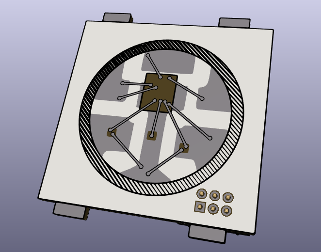
    Rev 4 of the shitty pixel showed up this week. I made some small tweaks to the art to get things closer to how I envisioned it. I blacked out the IC chip at the center of the pixel. It was bare substrate before this rev, letting light through, but I at least wanted to see what it would look like covered in silkscreen, I think I'm going to keep it this way. I also worked on creating some definition between the large copper areas and the thin areas that represent the bond wires. I think this came out nicely!

    Circuitry wise, I added 4 resistors and some pads for ICSP programming. Being new to this, it was really interesting to find out that you can re-program chips in circuit. If I understand all the research I did correctly, I needed to add pull-up resistors for the i2c communication as well as isolating the LEDs that shared pins that are needed for ICSP. I tested this on a breadboard before committing and I was very curious if it would work out when I got the actual boards. 

  • Order of Operations

    blinkingthing04/22/2019 at 23:08 0 comments

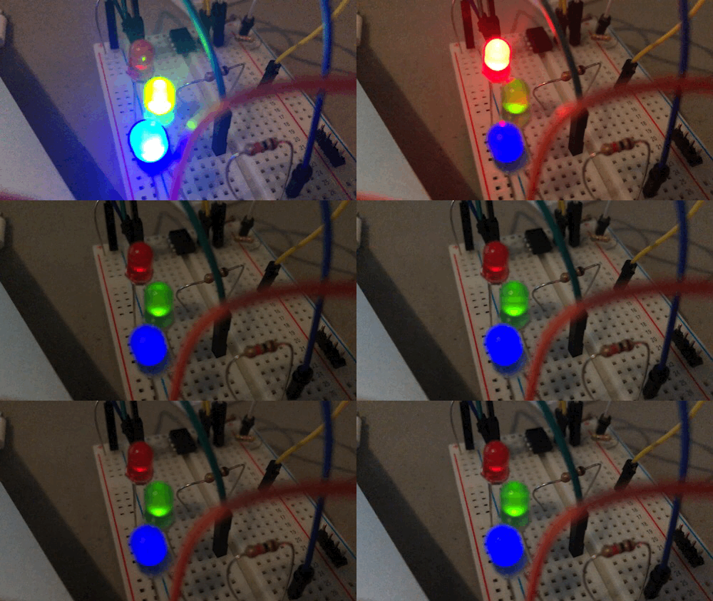
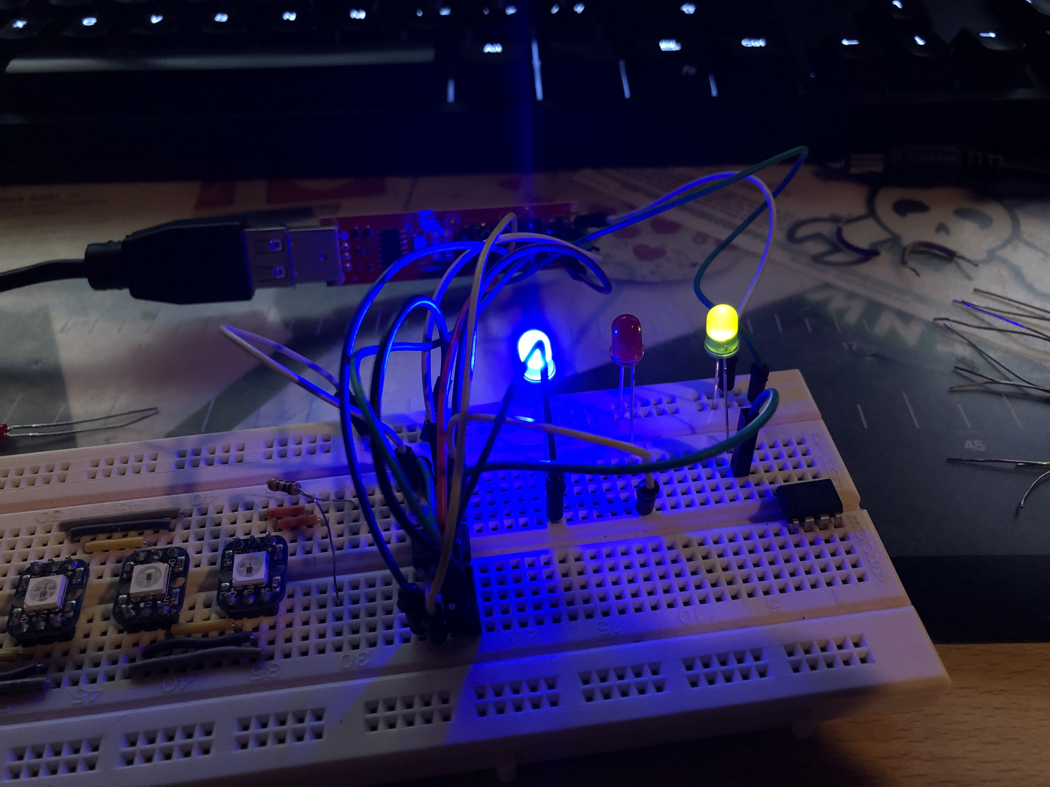
    Shitty Pixel on a Breadboard
    Blinking!

    The way I approached this project was odd. I wouldn't call it efficient. 

    I started with the art when I probably should've thought about the functionality first. But then again, I had a much more solid grasp on the art because that's what I'm familiar with. I've had experience screen printing in the past and designing the artwork for this SAO was very reminiscent of some of the printmaking projects I've worked on in the past. My first two iterations of PCBs were fueled by artistic decisions with little to no attention paid to the functionality of my circuit. Now, as I am figuring out my circuitry, I find myself going back to KiCad and editing the schematic and pcb, and then making a bunch of edits to the silkscreen layer of art to accommodate the changes to the pcb layout that I've made. 

    I now understand why I've seen so many badge makers start with an artless rectangular prototype board. I just had a lot to overcome as far as deciding what I wanted the SAO to actually do and how I would make it happen. 

    Thankfully, the ANDnXOR crew shared a handy SAO reference design on github that helped shape the direction I was to take my SAO. I also went through everything that Krux and Darknet have made available about their badges and Eggplant SAO. In addition to the online resources, I had my badges and SAOs from DC26 to draw inspiration from. I really liked how the Darknet badge could change the LED animations on the Eggplant SAO, and this seemed like something I could emulate without TOO much trouble. Reading through the ANDnXOR SAO documentation, I was really really intrigued by the idea of a badge being able to identify an SAO via data stored in EEPROM on the SAO. Both the EEPROM and LED control went way over my head but I want to learn. 

    I at least had a plan now. Add a microcontroller to blink LEDs and accept I2C commands to change the animations and an EEPROM chip to store info about the SAO. I went with an ATtiny85 and AT24C32 respectively. I ordered some parts from Digikey and got to breadboarding when they arrived in the mail. 

    After settling on an ATtiny controlled by i2c, I ended up finding an arduino sketch someone had written that could control an RGB LED with an ATtiny85 via i2c. How fortunate. This was a great place to start learning about i2c and being able to apply it immediately to my SAO. This involved a serious RTFM lesson. 

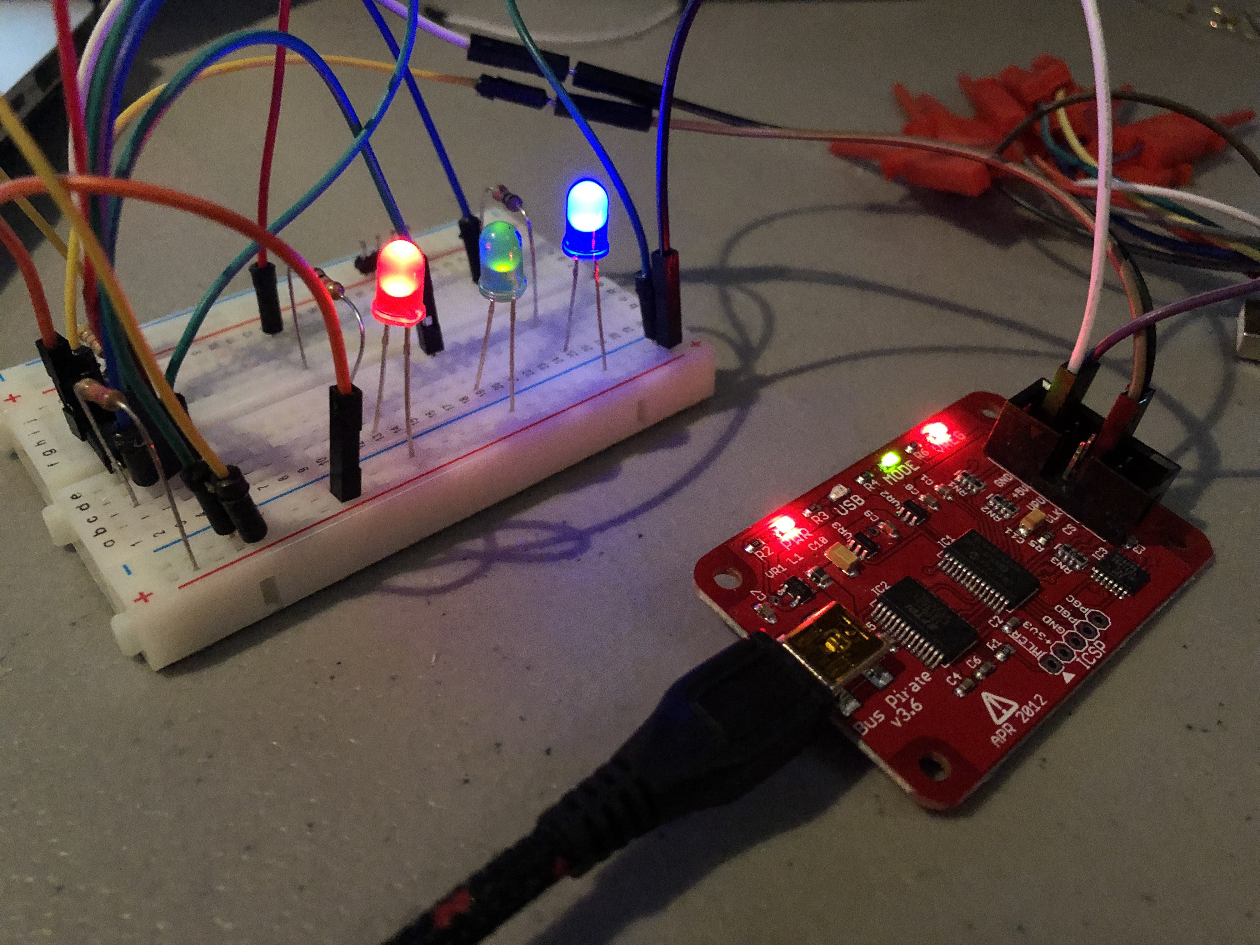
    Breadboard Shitty Pixel and Bus Pirate
    Bus pirate talking to the shitty pixel

    I had a lot of trouble figuring out the I2C com. This is partially because I have never used it before, but also because I'm super impatient and refuse to read documentation as thoroughly as I need to. I have a bus pirate, and it turns out those are really good for sending i2c data. I didn't know this because I've never actually used the bus pirate before. I had purchased it 2 years ago when I started going to Defcon and Hackaday Supercon as I heard it was a good tool for hardware hacking. I'm looking forward to making a list of all the basic skills and tools that I'm getting around to learning/using for the first time because of #badgelife. 

    After watching this video on i2c/bus pirate usage , sending a whole bunch of i2c reads and writes that did seemingly nothing (NACK NACK NACK), and taking my time to read the data sheets for my components (this is so important), I finally had it figured out and communicating consistently. 

    This is great. I now have the circuitry and functionality figured out. This is probably where I should've started. 

    I was even able to add a bit of a flag/puzzle in the SAO. This makes me very happy as that is one of my favorite aspects of the other conference badges I've seen. 

    The latest version of the board coming my way has a 6-pin ICSP footprint included to hopefully allow me to reprogram the SAO after they are assembled, it also has what should be the last bit of big tweaks to the artwork. The ICSP bit is working on a breadboard...

    Read more »

  • It Blinks!

    blinkingthing04/16/2019 at 16:22 0 comments

    Rev 2

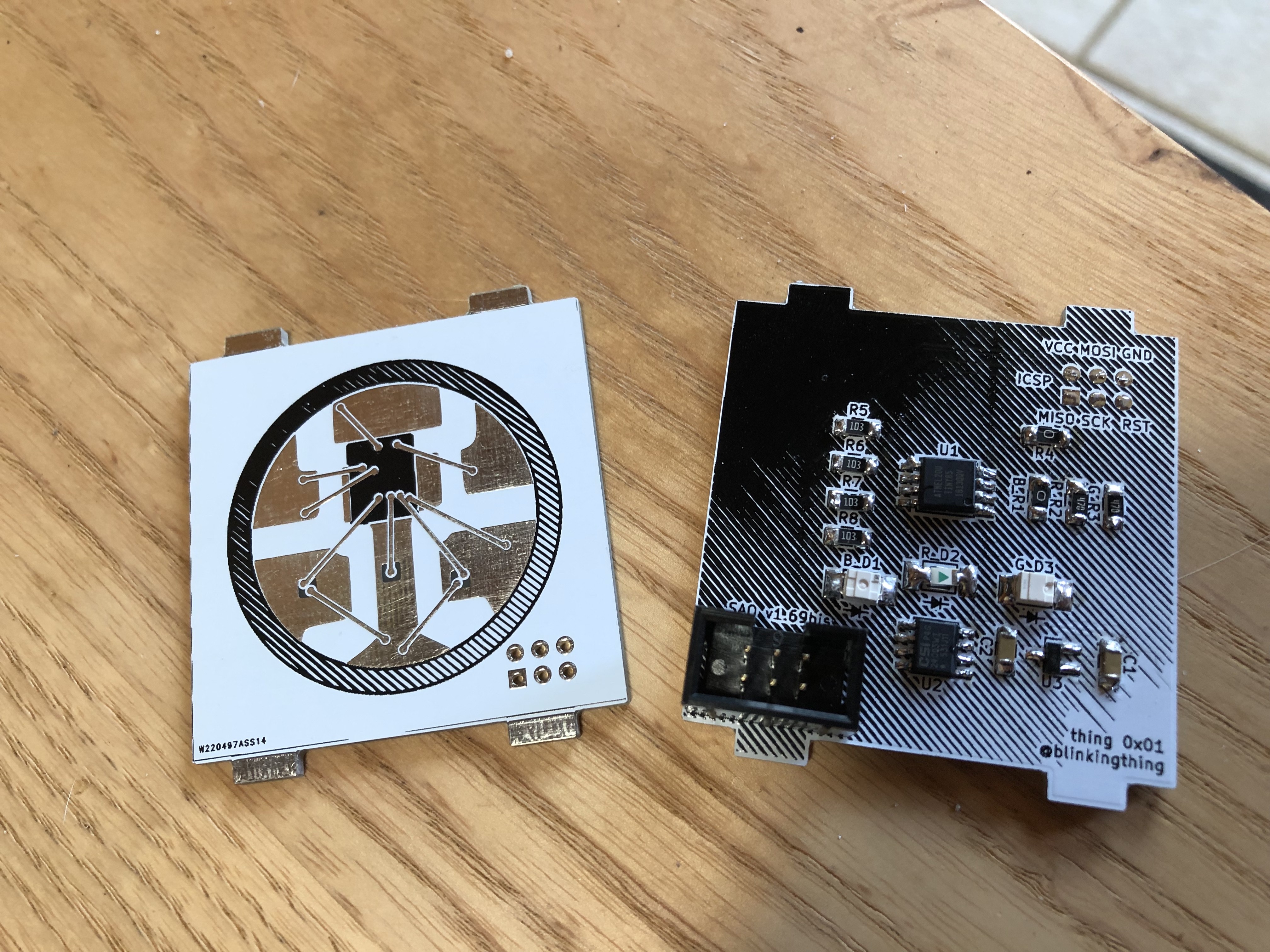
    The 2nd version of the shitty pixel SAO boards showed up yesterday and I was eager to get components on them. This revision has dramatically altered artwork, more along the lines with what I originally envisioned. I inverted the black and white, edited some copper areas to reflect the shiny silver parts of a WS2812 and left the area that represents the IC controller for the WS2812 unfilled to potentially let more light from the LEDs show through the front. I was hoping that this area would take on the color of the combined light from the 3 different LEDs. 

    Top view

    I decided to switch from 1206 led's to a reverse mount gull wing PLCC2 package LED. I used some Osram TOPLED and some from SunLED as I couldn't find all the colors I want in the Osram TOPLED brand from digikey. This required that I make a custom footprint. I got the required specs for the different LEDs I chose from the datasheet on the product's digikey page and decided on dimensions for the footprint that would accommodate both the Osram and SunLED brand led's. 

    I also moved the SAO connector towards the center of the board slightly so that it wouldn't overhang past the edges of PCB, an error I made on Rev 1 where I wasn't using the SAO connector footprint but instead was using a generic 02x03 pin header footprint. 

    back view

    Now it's Smart

    Another big addition to this board was the attiny85. I desperately wanted some more functionality from this add on, mainly the ability to blink. Otherwise my handle would be put to shame. An attiny microcontroller seemed like the way to go based on my severely limited knowledge and experience. I liked the idea of being able to use the Arduino IDE to write the software as that's something I'm fairly familiar with. 

    I looked to the Darknet Eggplant SAO to help guide this design. That board was designed with pads to allow for in-circuit programming of the microcontroller. I briefly read through some documentation on how to design a circuit that would be compatible with in-circuit programming, but didn't get the ideas fully fleshed out and decided to forgo this for this rev of the board. This lead to me mangling the first SMD attiny85 I tried to hook up with IC hooks to my AVR programmer. 

    shitty pixel b/w 6x IC hooks

    Too Many Hooks in the Kitchen

    I remember thinking about this step in the process while I was designing the PCB's thinking that it wouldn't be too much of a hassle. Turns out it kind of is. The process of soldering the chip to the board, hooking it up, and programming it will take me way too long if I want to create any number of these. I want to go down the in-circuit programming route as it will allow me to fix anything that comes up post-production, plus the end user could hack away at it if it had it's programming pins exposed. 

    Populated and energized back view

    Assembled by Hand

    After programming the attiny, I went ahead and put the rest of the components on the board and it actually fired up as expected. I used 0805 resistors even though this board is designed to use 1206 size, I just didn't have time to order them and wanted to see if I could make it work with the 805's. I think I'm going to reposition R1 so it's not so close to the SAO connector for the version. I also want to leave a blank spot on the back for the board manufacturer to print their inventory number  (I assume it ended up on the front this time because I didn't leave them any room on the back.) 

    I'm curious if I'm going to go down the road of having the PCB manufacturer place and solder the components for me all in one go. I still have to weigh out my options. 

    Front view

    RGB

    With the altered artwork, light shines through the board slightly differently than the previous version. The small squares are illuminated solidly as well as the areas beside the bond wires. I really like the way the light sort of looks like it's drawn up the bond wires via capillary action and mix in the center where the controller...

    Read more »

  • the Next Iteration

    blinkingthing04/09/2019 at 19:41 0 comments

    I've been torn on what features I wanted to include on this add on. I wanted to land someplace between LED's that turn on and a full fledged serial-talking EEPROM-having thing that I don't understand all the way. 

    I read through the documentation of and played with my badges and add-ons from DC26 trying to find inspiration. I love the ammount of interactivity between the Darknet badge and it's Eggplant SAO and I want to replicate something like it, but alot of what makes it work goes too far over my head so I probably need to tone things down a bit. I also went through the ANDnXOR github and checked out the SAO reference designs they've put up for this coming defcon. I really like the idea of putting in an EEPROM and having some sort of badge/SAO communication/identification but again, these concepts are going over my head and I don't really have the time/patience to read, experiment, fail and eventually learn at the moment.

    At the very least I wanted the LEDs to blink in some fashion. I started playing with LED sequencer circuits using a 555 + 4017 IC. While this was an interesting exercise, figuring out the animations I wanted wasn't going to work with this circuit. 

    My other option would be a microcontroller. I decided (without much research) on an attiny85. It was a really good experience learning how to put arduino code on the attiny, something I had never done before. Using the micro I am much more satisfied with the control I have over the LED animation. I also now have an opportunity to try and utilize an input signal coming from the badge over one of the new pins that came along with the new SAO standard. 

    I got a working breadboard circuit going before re-desigining the PCB. I can reprogram the attiny85 so long as it's not connected to the rest circuit, so my plan is to finalize the code and flash the chips before soldering them to the board, at least for the next prototype. I'll look into having PCBWay program the chips and assemble them for the final batch, but I'm already curious if I have enough lead time to that kind of thing. I guess we'll find out. 

    After semi-settling on a circuit I went back through and redesigned the graphics for the PCB in Inkscape, svg2shenzen'd them again and put everything in KiCad. Between the last design and this one I've decided to swap out components. I'm swapping the 1206 leds for some OSRAM reverse mount PLCC2 LEDs.  These are a bit bigger and hopefully easier to solder. Same with the resistors, I'm switching from 0805 to 1206 to try and make it a little easier to solder. This required switching out the footprints I had been using.

    I put a little bit of effort into labeling things and making sure they were legible even with all the line art I have going on on the back of the board. This required a bunch of back and forths between KiCad and Inkscape to get everything just write. Huge shout out to MrTwinkleTwinkie as his youtube SAO streams made this a lot easier to wrap my head around. At one point I caught a mistake in my back masking in the 3d viewer, I didn't leave a gap in the mask to let the light through the back of the board! Another thing I did, not sure if it's a mistake or not, was to remove the silkscreen circle that was noting the VCC pin on the SAO header. It was interfering with the artwork on the front of the board so I just removed the offending circle from the connector's footprint in KiCad. This may be a no-no, but I'm not sure. 

    That's where I'm at now. Just submitted these designs to PCBWay. Now I wait...

  • Have You Ever Started a Project on Step 3?

    blinkingthing04/02/2019 at 17:02 0 comments

    One of my strengths is being very driven, but one of my weaknesses is not doing enough research ahead of time before jumping into something new full steam.

    I got very excited looking at the PCBWay site and slammed through the pcb design process without thinking much about what I wanted in the end. Now I think I need to figure it out. My initial design has 3 LEDs that are directly wired to ground at power, so they're always going to be on. That is boring. I want a little bit of functionality in my add-on. I started looking at 555 / 4017 LED chaser circuits. I wired one up on a breadboard and while I found it a very informative and fun exercise, I wasn't satisfied with the animations I was getting with that circuit. I've moved onto thinking about an Attiny85. Partially because I was still thinking about using WS2812b LED's on this add-on but also because they seem similar to Arduino's and I'm familiar with those. 

    Using an Attiny85 I can easily create the animations I want to see with the LED's but I'll also be able to add some sort of unique functionality. I'm intrigued by the aspect of add-on to badge communication. Looking at the DC Darknet badge from 2018, I really like how you an scan for shitty add ons and the badge's OS reports to you the name of the add-on that is plugged in. I only have the Darknet Eggplant add on, so I don't know if this functionality existed with any other badge/add-on combinations. I've read up a bit on AND!XOR's SAO reference and that sheds some light but I'm still not sure about it. 

    Something I am a little more sure about is the actual blinking functionality of the add-on. I got a bunch of animations programmed on an arduino with 3 LEDs and then I needed a way to switch between the animations. One of my favorite features on a lot of badges I've seen has been capacitive touch sensing. This seemed like a good way to give the end user a button without adding a button to the parts list. I downloaded the CapSense library, threw a 1M resistor across two pins and was pretty much good to go. 

    The circuit works as well as I could want it to. I'm thinking I may have to switch out the CapSense resistor for a different one if the circuit doesn't work as well on the actual board? I will also probably modify some of the LED animations at some point, but I felt comfortable trying to move the programming of an Arduino UNO onto the Attiny85 chips I had ordered. 

    To do this I used the Arduino IDE and Arduino UNO as ISP following this guide. It worked really smoothly (as long as you follow all the instructions) ((I tried to go without the capacitor between GND and RESET on the Arduino, didn't work...))

    The had to re-arrange which pins I was using for what when switching from the Arduino and Attiny. I ended up using pins 0, 1 and 4 on the Attiny85 for the LEDs as these are PWM outputs. I'm using 3 and 5 for the CapSense circuit and have one pin, number 2, left to try and do something with. I'm bummed that it's not enough for I2C but I still haven't fully wrapped my head around the badge/add-on addressing. 

    Now I have my Arduino Sketch running 95% correctly off an Attiny85. Very cool. (One LED isn't behaving correctly in some of the animations but I can handle that). Being that my board will require an Attiny85 now, I'm starting to think about either getting the microchip programmed during the manufacturing process, or adding in a 6 pin ISP header into my design so I can re-flash the boards using some sort of pogo-pin jig down the line. This might be easier than having the board manufacturer program the boards, not entirely sure.

    I'm enjoying figuring out this process. My process probably appears a bit haphazard but it's (sort of) working for me.

    This MrTwinkleTwinkie stream popped up the other day and was really helpful pointing out how I should've done my board design last week. Between that and the Getting to Blinky 4.0 series by Contextual Electronics I'll be better prepared when...

    Read more »

  • That was fast

    blinkingthing03/30/2019 at 00:51 0 comments

    I've received the first shitty pixel boards. While I'm amazed at how fast the turnaround was, I think I need to slow down and think slightly more between steps. 

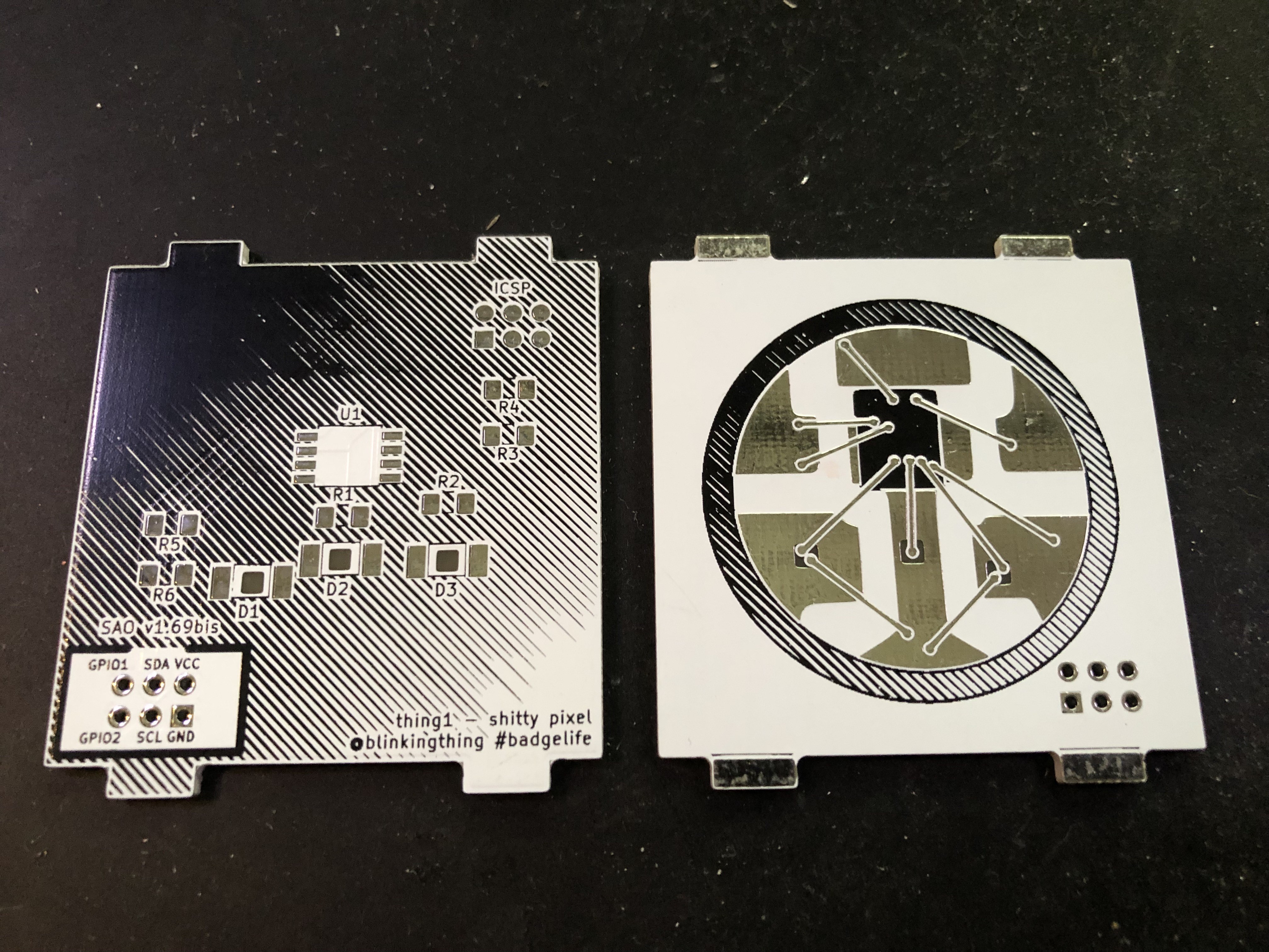
    Nearly instantaneously after my initial design was approved, I discovered/realized a few things that I would need to change. First off, I didn't know that there was a KiCad footprint for the SAOv1.69bis standard. I instead used a generic 2x3 pin header footprint. While this technically works, using the generic footprint allowed me to place the footprint so close to the edge of the board that if you solder on a shrouded 2x3 connector like I plan to, the connector overhangs the board. I would've realized this had I used the 'official' KiCad footprint from the beginning. Slightly frustrating but I'm really happy to learn. 

    Next to think about are the colors. I mentioned this in a previous post but I haphazardly chose white soldermask and black screenprinting when I saw the cost of the black matte soldermask I had initially considered. I don't know why I didn't choose black soldermask with white screenprinting, because this would've at least shown me a visual approximation of my intended design. Instead, I got this wacky inverted colorway but again, it has me thinking about what I want to do for the next iteration. 

    I have components shipping from digikey at the moment but wont be able to assemble this and test it for a few days. I did get some shrouded connectors delivered and tried setting up the shitty pixel on top of an actual badge to see if I was happy with size and placement of the badge connector. I think I might need more mounting options. It might be nice to be able to solder the connector onto one side or the other so that it can hang off to the left or right of the badge it's attached to. I'm pretty happy with the size though, I didn't want to go 100x100mm thinking it would be far to big, so I started at a 50mm square.

    As previously mentioned, the backside of the add-on needs some attention. I've mocked up a face to put on the back but I haven't settled on that whatsoever. I also believe I'll be removing "defcon 27" from the back as this is an unofficial add-on, I don't feel I have the right to put the defcon name on this, plus shitty add-ons show up outside of defcon. Everything I needed to do to allow light to pass through the substrate seems to be correct. I'm excited to see this with actual LEDs mounted to it.

    To RGB or not to RGB ?

    I designed this board as the thoughts were flowing out of my brain. The first thought three individual single color LEDs. One red, one blue, one green. With the new 1.69bis SAO standard, I keep thinking about how fitting it would be if this add-on had some WS2812b's on it that could be controlled via it's badge host. This seems like a great meta idea being that the design of this add-on is based on a WS2812b but also because it will force me to learn a little more. I believe this would also make the add-on a lot more interesting to others as well. 

    If I do switch out the single color LED's for WS2812b's, I want to be able to have an onboard program running the lights with the option to switch to the data stream coming from the badge. I have no idea how to handle this intellegently, but I figured I could put a physical toggle switch on the add-on to switch between data streams. I tested this with an arduino running a neopixel example sketch with two different animations on two different pins. I wired up a few neopixels to the arduino with a toggle switch in line to switch between the two different data sources. I switched it back multiple times while the program was running and it seemed to handle it OK. Clearly there are some timing hiccups when you switch between the streams, but eventually (~1-2 seconds) the correct animation starts playing. This is proof enough for me that I could have an on-board program running with a physical switch that toggles to the badge's pixel data stream. I'm sure there's...

    Read more »

View all 13 project logs

Enjoy this project?

Share

Discussions

Tillo wrote 06/04/2019 at 07:12 point

They look great. Is there any chance to get one without beeing at DC?

  Are you sure? yes | no

blinkingthing wrote 06/04/2019 at 13:35 point

  Are you sure? yes | no

Mike Szczys wrote 04/08/2019 at 16:58 point

Great design. Anyone who's looked close at a WS2812 will know it immediately. Nice!

  Are you sure? yes | no

Sophi Kravitz wrote 03/27/2019 at 18:43 point

Cool! It will be satisfying once complete. You can add art to that big blank area, make the art have LED eyes ;)

  Are you sure? yes | no

blinkingthing wrote 03/27/2019 at 16:22 point

the bond wires will be part of the copper layer on the front side of the circuit board. At least that was my first thought.

  Are you sure? yes | no

Gerben wrote 03/27/2019 at 14:12 point

Cool idea. Any idea of how to do the bond-wires?

  Are you sure? yes | no

Similar Projects

Does this project spark your interest?

Become a member to follow this project and never miss any updates